Schauer CM12A User manual
1
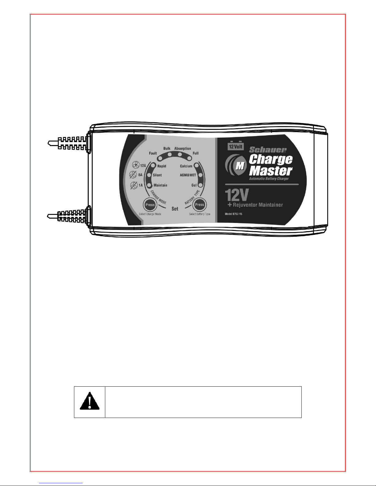
User Manual
12 Volt Battery Charger
1/4/6 Amp & 1/8/12 Amp
Plus
Battery maintainer and Rejuvenator
Model No. CM6A (0757-14CEC) / CM12A (0757-15CEC)
THIS MANUAL CONTAINS IMPORTANT SAFETY AND
OPERATING INSTRUCTIONS
READ ENTIRE INSTRUCTION BEFORE USE

2
WARNING - RISK OF EXPLOSIVE GASES WORKING IN VICINITY OF A LEAD-ACID BATTERY IS
DANGEROUS. EXPLOSIVE GASES DEVELOP DURING NORMAL BATTERY OPERATION. IT IS
IMPORTANT THAT EACH TIME BEFORE USING YOUR CHARGER, YOU READ THIS MANUAL AND
FOLLOW THE INSTRUCTIONS EXACTLY.
To reduce risk of battery explosion, follow these instructions and those published by battery manufacturer
and manufacturer of any equipment you intend to use in vicinity of battery. Review cautionary marking on
these products and on engine.
Do not expose charger to rain, snow, or liquids.
Use of an attachment not recommended or sold by the battery charger manufacturer may result in a risk of
fire, electric shock, or injury to persons.
To reduce risk of electric shock, unplug charger from AC outlet before attempting any maintenance or
cleaning.
To reduce risk of damage to electric plug and cord, pull by plug rather than cord when disconnecting charge
An extension cord should not be used unless absolutely necessary. Use of improper extension cord could
result in a risk of fire and electric shock. If extension cord must be used, make sure that pins on plug of
extension cord are the same number, size and shape as those of plug on charger and that the extension
cord is properly wired and in good electrical condition and that the wire size is large enough for A.C.
ampere rating of charger as specified in the following table:
RECOMMENDED MINIMUM AWG SIZE FOR
EXTENSION CORDS FOR BATTERY CHARGERS
Length of cord (feet): 25 50 100 150
AWG size of cord: 16 16 16 14
If charger is equipped with an input power cord, do not operate charger with damaged cord or plug -
replace the cord or plug immediately.
Do not operate charger if it has received a sharp blow, been dropped, or otherwise damaged in any way;
take it to a qualified serviceman.
Do not disassemble charger; take it to a qualified service center when service or repair is required.
Incorrect reassembly may result in a risk of electric shock or fire.
Appliances incorporating batteries which contain materials hazardous to the environment.
Batteries contain lead and dilute sulfuric acid. Dispose of the battery in accordance with federal, state and
local regulations. Do not dispose of the battery in a landfill, lake or other
Scrap and replace the VRLA battery at or before the time indicated on the battery or in the user's manual.
Usage beyond the required time of service can cause fluid leakage due to damages to the container, or
cause fire due to power leakage.
PERSONAL PRECAUTIONS
The appliance is not intended for use by young children or infirm persons without supervision; young
children should be supervised to ensure that they do not play with the appliance.
When the battery charger is charging for automobile batteries, the following steps should be done:
The battery terminal is not connected to the chassis has to be connected first. The other connection is to
be made to the chassis, remote from the battery and fuel line. The battery charger is then to be connected
to the supply mains.
After charging, disconnect the battery charger from supply mains, and then remove the chassis connection
and the battery connection, in this order.
For appliance with type Y attachment:
If the supply cord is damaged, it must be replaced by the manufacturer or its service agent or similarly
qualified person in order to avoid a hazard.
Someone should be within range of your voice or close enough to come to your aid when you work near a
lead-acid battery. Have plenty of fresh water and soap nearby in case battery acid contacts skin, clothing or
eyes. Wear complete eye and clothing protection. Avoid touching eyes while working near battery.
If battery acid contacts skin or clothing, wash immediately with soap and water. If acid enters eye,
immediately flush eye with running cold water for at least 10 minutes and get medical attention immediately.
NEVER smoke or allow a spark or flame in vicinity of battery or engine.

3
Be extra cautious to reduce risk of dropping a metal tool onto battery. It might spark or short-circuit battery
or other electrical part that may cause explosion.
When working with a lead-acid battery, remove personal metal items such as rings, bracelets, necklaces,
watches, etc. A lead-acid battery can produce a short-circuit current high enough to weld a ring or the like
to metal, causing a severe burn.
It is not intended to supply power to a low voltage electrical system other than in a power supply
application. Do not use battery charger for recharging dry-cell or non-rechargeable batteries that are
commonly used with home appliances. These batteries may burst and cause injury to persons and damage
to property. While charge the impropriety type of battery will cause battery serious damage.
NEVER charge a frozen battery.
NEVER charge the impropriety type of battery.
NEVER charge the impropriety Voltage of battery.
NEVER block off the ventilation louver of the chrger.
PREPARING TO CHARGE
If necessary to remove battery from vehicle to charge, always remove grounded terminal from battery first.
Make sure all accessories in the vehicle are off, so as not to cause an arc. Be sure area around battery
is well ventilated while battery is being charged. Gas can be forcefully blown away by using a piece of
cardboard or other non-metallic material as a fan.
Clean battery terminals. Be careful to keep corrosion from coming into contact with eyes. Add distilled
water in each cell until battery acid reaches level specified by battery manufacturer. This helps purge
excessive gas from cells. Do not overfill. For a battery without caps, carefully follow manufacturer's
recharging instructions.
Study all battery manufacturers’ specific precautions such as removing or not removing cell caps while
charging and recommended rates of charge.
Determine voltage of battery by contacting battery manufacturer and make sure it matches output rating of
battery charger.
CHARGER LOCATION
Locate charger as far away from battery as dc cables permit.
Never place charger directly above battery being charged; gases from battery will corrode and damage
charger.
Never allow battery acid to drip on charger when reading gravity or filling battery.
Do not operate charger in a closed-in area or restrict ventilation in any way.
Do not set a battery on top of charger.
DC CONNECTION PRECAUTIONS
Connect and disconnect DC output terminals only after removing charger from AC outlet.
Never allow DC output terminals to touch each other.
If problems arise connecting the output leads, solicit the aid of your Dealer from whom you purchased this
product or the charger manufacturer for finding a suitable connection device for your application.
FOLLOW THESE STEPS WHEN BATTERY IS INSTALLED IN VEHICLE. A SPARK NEAR BATTERY
MAY CAUSE BATTERY EXPLOSION. TO REDUCE RISK OF A SPARK NEAR BATTERY:
Position AC and DC cords to reduce risk of damage by hood, door or moving engine part.
Stay clear of fan blades, belts, pulleys, and any other parts that can cause injury to persons.
Check polarity of battery posts POSITIVE (POS., P, +) post usually has larger diameter than NEGATIVE -
(NEG., N, -).
Determine which post of battery is grounded (connected) to chassis.
For negative-grounded vehicle, first connect POSITIVE (RED) clip from charger to POSITIVE (POS., P, +)
ungrounded post of battery. Then connect NEGATIVE (BLACK) terminal to vehicle chassis or engine block
away from battery.
For positive-grounded vehicle, connect NEGATIVE (BLACK) clip from charger to NEGATIVE (NEG., N, -)
ungrounded post of battery. Connect POSITIVE (RED) clip to vehicle chassis or engine block away from
battery keeping the battery terminal well removed there from.
Do not connect any charger clips to carburetor, fuel lines, or sheet-metal body parts. Connect to a heavy

4
gauge metal part of the frame or engine block.
Connect charger AC supply cord to electric outlet.
When disconnecting charger, turn switches (if supplied) to off, disconnect charger from AC power, remove
clip from vehicle chassis, and then remove clip from battery terminal. See operating instructions for length
of charge information.
FOLLOW THESE STEPS WHEN BATTERY IS OUTSIDE VEHICLE. A SPARK NEAR THE BATTERY
MAY CAUSE BATTERY EXPLOSION. TO REDUCE RISK OF A SPARK NEAR BATTERY:
Check polarity of battery posts. POSITIVE (POS., P, +) battery post usually has a larger diameter than
NEGATIVE (NEG., N, -) post. Some batteries are equipped with 'Wing-Nut' terminals allowing for easy
placement of the terminals to these posts.
Attach at least a 24-inch long 18-gauge (AWG) insulated battery cable to NEGATIVE (NEG., N, -) battery
post.
Connect POSITIVE (RED) charger terminal to POSITIVE (POS., P, +) post of battery.
Position yourself and free end of cable as far away from battery as possible - then connect NEGATIVE
(BLACK) terminal to free end of cable.
Do not face battery when making final connection.
Connect charger AC supply cord to electrical outlet
When disconnecting charger, always do so in reverse sequence of connecting procedure and break first
connection while as far away from battery as practical
A marine (boat) battery must be removed and charged on shore. To charge it on board requires equipment
specially designed for marine use.
MAINFEATURES:
Smart Charge plus Maintenance and Rejuvenation
Easy to Use: Easy to operate and requires no technical experience.
Fully controlled by Microprocessor
Battery initial condition diagnose
Enhanced battery rejuvenation (patented technology)
Battery voltage retention analysis
Peak pulses for long term maintenance
Ultra lower power consumption ( ECO mode)
Multi Charge Stages:
oQualification - Battery condition check
oBattery rejuvenation
oSoft Start
oBulk Charging
oAbsorption Charging
oEqualizing Charging
oVoltage analysis
oFloat Mode
oLong term maintenance pulse charge
Diagnosis & Charge - Automatic diagnosis and charge: On power up, the charger
will automatically diagnoses the battery condition, and then determine if the battery
charger engages the rejuvenation stage or goes into charging cycle.
Enhanced battery rejuvenation stage –Patented battery rejuvenation technology:
The charger has a unique and patented rejuvenation feature which uses with high
voltage equalizing and peak pulse reconditioning to repair the sulphated batteries,

5
this feature is fully automatic and subjected to the internal impedance of the battery.
Charge & Maintain - Automatic Maintenance: The battery charger could be left
unattended and it is full time managed by program; when the battery is charged to
"full" state, the charger automatically switches to maintain the battery. It will monitor
the battery voltage and continue to peak performance with special pulse charge in
long term maintenance.
Short circuit or Reverse polarity protection: The charger will automatically turn off
when the output short circuit or reverse polarity occurred and prevent any damage.
Never overcharge your battery
Heavy-Duty cables
Corrosion-resistant output connectors
Output clips and ring terminals provided: It comes with a quick connect fly lead and
2 different kinds of connectors, crocodile clips and a ring terminals. The ring
terminals are perfect for permanent connection to your battery. You can connect the
lead to the battery and tuck the lead away while you are using your vehicle and when
you get back to your garage simply plug the lead back into the charger.
TEMPERATURE & SAFETY PROTECTION:
The charger contains the following safety protections:
INTERNAL OVERHEAT PROTECTION: The battery charger is built-in with overheat
and overload electronic circuit. When the charger is overheated, the charger will
decrease the charging current. If temperature is decreased, the charger will resume
to normal charging.
TIMER PROTECTION: The charger provides the maximum charging timer
management for each charging stage; this condition may occur if attempting to
charge any severely discharged or heavily sulfated battery. Once the charger is
timed-out, the charger will stop charging for protecting your battery and the RED
LED will be FLASH fast, while this situation occurs, please check with your battery
statues.
REVERSE POLARITY: The charger has reverse battery protection. If a reverse
battery exists (Red LED ON, while output leads are connected backwards), simply
unplug charger from AC power and properly remake the connections as described
in this manual.
SHORT CIRCUIT PROTECTION: The charger has output short-circuit protection. If
the charger output lead short condition exists (Red LED ON, while output leads are
connected backwards), simply unplug charger from AC power and properly remake
the connections as described in this manual. The charger employs the firm
hardware and smart program to automatically detect the output connections. Once
the charger detects the output short-circuit or reverse polarity, it will not deliver any
output current.
ECO MODE FOR ENERGY SAVING:
This battery charger has built in ultra-low power consumption circuit and operated with very
high power efficiency, the charger will automatically go into ECO mode if load unattached.
This manual suits for next models
3
Table of contents
Other Schauer Batteries Charger manuals


