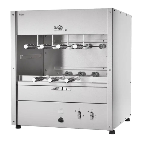
Scheer LVR 350A User manual

MP-000022 - A
WARNING: Improper installation, adjustment, alteration, service or
maintenance can cause property damage, injury or death. Read the installation,
operating and maintenance instructions thoroughly before installing or
servicing this equipment. Maintenance and servicing must be authorized by the
manufacturer who will advise correct service company.
WARNING FOR YOUR SAFETY: Do not use or store gasoline or other
flammable vapors or liquids in the vicinity of this or any other appliance.
WARNING:
Do not spray aerosols or combustible oils in the vicinity of this appliance
while it is in operation.
SCHEER CHURRASQUEIRAS E ACESSÓRIOS
CONGRATULATIONS!
You just bought a barbecue grill with the highest technology, design and performance.
Now, it will be much easier and faster to prepare your Churrasco. SCHEER
CHURRASQUEIRAS thanks for your choice.
For your barbecue to perform best, read this manual carefully and follow the
instructions correctly. For any questions, information or suggestions please contact us that a
well qualified professional will be pleased to assist you.
Scheer Churrasqueiras e Acessórios Ltda

MP-000022 - A
CONTENT
WARNINGS ……………………………………………………………………………………02
IMPORTANT INFORMATION....................………………………………………………….04
INTRODUCTION TO OPERATOR .................................................................................04
SAFETY RULES …………………..…………………………………...…..……………........05
TRANSPORT .………………………………………………………………….………...........05
REMOVING THE PACKAGE …………………………..……………………....…………….06
DESCRIPTION …….....................................……………….………………….……………07
INSTALLATION.........……………………………………………………..….……….............08
PLACE OF INSTALLATION/ APPLIANCE
CONNECTION.…………………………………………………………………….09
PILOTS/BURNERS LIGHTING PROCEDURE …………………………………………… 11
WATER AND GAS INSTALLATION .................................................................................11
ADJUSTS AND CHECKING .....................………………………………………………….14
PREVENTIVE MAINTANACE .................………………………………...…………………17
REMOVING BURNERS .............……………………………………………………………..17
CHANGING THERMOCOUPLES…………………………………………………………….18
ACCESSING THE BACK SIDE...........................………………………………………......19
BACK VIEW .......……………………………………………………………………………….20
ELETRICAL DIAGRAM...................................................................................................21
LUBRICATION................................................................................................................22
CLEANING......................................................................................................................23
EXTRA INFORMATION... ……………………………………………………….……………24
WARRANTY ..................................................................................................................25

MP-000022 - A
SCHEER CHURRASQUEIRAS E ACESSÓRIOS
IMPORTANAT INFORMATION:
•Keep this manual for future information in an easily accessible location;
•Installation of the product is the responsibility of the buyer. The installation must be carried
out in accordance with the manufacturer's instructions and carried out by qualified and
competent persons;
•In the case of repairs, use only service authorized by the manufacturer and ask for original
or quality spare parts;
•Failure to operate this equipment could endanger the product and the operator of the
equipment;
•For technical assistance nearest you, contact a trusted distributor or directly with the
manufacturer;
•The manufacturer reserves the right to change this manual at any time.
•This equipment must be installed in accordance with the local regulations and codes of the
destination;
•Keep this product out of the reach of children especially after use when the grill is cooling;
INTRODUCTION TO OPERATOR
•This manual contains technical information for the correct installation and operation of this
equipment. The operator of the equipment has the duty and responsibility to follow the
correct instructions;
•Before using this equipment, it is necessary to consult this manual. We recommend strict
reading and that the instructions are strictly followed. Keep the manual in perfect condition;
•This manual is part of the equipment and should be stored in a location that is easily
accessible and known to all operators and is also available to anyone responsible for
maintenance;

MP-000022 - A
SAFETY RULES
• Read and understand all instructions in this Manual before operating your LVR 500A Grill;
• The LVR 500A Grill is not intended for use by persons (including children) with reduced
physical, sensory or mental capabilities, or by persons lacking experience and knowledge,
unless instructed to use the appliance or Supervision of a person responsible for their safety;
• Always use the equipment with care and attention.
• The power cord should be examined regularly to detect possible damage. If it is damaged,
it must be replaced by the manufacturer, authorized agent;
TRANSPORT
• In order to unload the unit we recommend a truck with lift gate;
• Check for any signs of hits, drops or malfunctions with responsible for the transport and
contact Scheer sales department.
• The risks of transportation are the customer's responsibility. Any claim for damages during
transportation must be made at the time you receive the product, it must be communicated
to the carrier and also to the manufacturer of the product;
• As soon as you remove the product from the packaging, make a visual inspection to check
for possible damage during transportation;
• We recommend special care during this inspection to identify possible damage during
transport;

MP-000022 - A
REMOVING FROM ITS PACKAGE
The unit must be unloaded in a flat and firm place can be started the removal of the
barbecue from the packaging. After removing the top, side, front and rear cover, remove the
machine from the pallet, we recommend the use of a forklift.

MP-000022 - A
DESCRIPTION
Parts & Accessories:
• 1 unit;
• 1 manual;
• Skewers (quantity corresponding to the order at the time of purchase);
NOTE: The skewers and accessories are shipped separately from the unit;
Characteristics:
• Stainless steel AISI304 brushed or AISI430 brushed (as requested) and carbon steel;
• AC input 127 / 240V 50-60Hz (upon request);
• Degree of Protection: IPX 1;

MP-000022 - A
• Class Construction: Class 1;
• Rotating system;
• Motor 1/4 HP;
• 127VAC -1.65A Power 210W;
• 240VAC -1.2A Power 270W;
• Semiautomatic firing;
• Skewers with stainless steel blades;
Types of Gas Used:
• LPG or Natural Gas (as requested);
Gas consumption (m³ / h):
• Gas: Each burner consumes 0.3125 (m³ / h) of gas per hour at a pressure of 0.8 kPa
Natural Gas or 2.6kPa for LPG measured at the manifold test point (see location of this test
point on page14 detail D).
Rated Power per Burner:
• 16.880 MJ/h;
Energy consumption:
• Electrical power: 0.21 kWh -127VAC;
• Electricity: 0.27 kWh - 240VAC;

MP-000022 - A
INSTALLATION
• This installation must conform according local codes (AS/NZS 5601). In the absence of
local codes, the installation must conform to the National Fuel Gas Code, ANSI Z223.1,
Natural Gas Installation Code, CAN/CGA-B149.2, or the Propane Installation Code,
CAN/CGA-149.2. For installation under ventilation hood only. The manufacturer is not
responsible for installation. After all connections and installation is in conformity with this
manual, starting pilot/burners lighting procedure.
• Remove the Gas Barbecue from the packaging;
• The Gas Barbecue should be installed where there is air circulation;
• Make sure the Gas Grill is levelled;
• The rotating system requires 240 volt power. (Check that the voltage is correct);
• Make sure all removable components are properly secured: burners, pilot, protective cover,
bars, stones, manifold. Pressure in 0.8kpa Natural Gas or 2.6kPa for LPG measured at the
manifold test point (see location of this test point on page14 detail D).
• Installer can use suitable 3/4" gas hoses that complies with standard AS/NZS1869 Class B
or D. If a gas hose is used for connection, a suitable safety chain is to be installed that does
not exceed 80% of the length of gas hose, this chain is to be fixed securely to the appliance
& the rear wall.
• Gas installation should be done taking into account the number of burners in the Gas
Barbecue. Each burner consumes 0.3125 (m³/h) of natural gas. Therefore, the gas battery
must be made according to the flow capacity required by the burners (0.3125 m³ / h);
• Each burner corresponds to: 16.880 MJ/h.
• For installation a gas regulator gas valves must be used; for units with 1 meters there is
one gas inlet so just one valves will be used and for larger than 1 m units two gas inlets will
have in your unit so it is necessary two gas pressure regulator valves.
Notes:
• Consult the technical specifications of the barbecue and call a technician specialized in
gas; (Preferably the same as the contracted gas company);

MP-000022 - A
• The gas supply should not be restricted from the main meter to machine connection;
• Before turning the machine on, supply the water tank by filling it up to approximately 10 cm
from the bottom of the tray.
PLACE OF INSTALLATION
• The appliance should be installed 50mm clearances from other appliances & combustible
materials. Never obstruct the top, especially with furniture or any other material, as the
equipment will not function properly and there is a risk of fire;
• The appliance should be installed 50mm clearances from other appliances;
CAUTION: Do not use in outdoor locations. Do not install and use exposed to weather.
• For electrical installation and recommended a separate electric circuit with a 5A circuit
breaker exclusive to the unit;
• Always seek the assistance of a qualified professional.
APPLIANCE CONNECTION
• This appliance is supplied with castors and is to be connected to a fixed gas supply via a
flexible hose connection, a restraining chain or wire of adequate strength shall be fixed to the
appliance and be suitable to be fixed to the wall within 50mm of each connection point. The
length of the chain or wire shall not exceed 80% of the length of the hose assembly.
RELEVANT INFORMATION TO THE INSTALLER:
• Reference picture on next page to see where the chain/wire must be connect
• Unit is not supplied with chain/wire, neither a flexible gas hose, these parts must be
supplied by the professional installer.
INSTALLER: Installer needs to supply 3/4" non kink gas hose with fittings & safety chain with
suitable fixings to secure on wall & rear panel of appliance.

MP-000022 - A
Appliance –Fixing spot drawing:

MP-000022 - A
LVR 350A:
Frontal view:
“A” Pilot Valve.
“B” Burners adjusment valves
“C” Safety gas valve.
“D” Ignitor.
“E” Up/down grilling system switch
“F” Water inlet valve
“G” On off switch for the rotisserie system

MP-000022 - A
PILOTS/BURNERS LIGHTING PROCEDURE:
1 –Turn the gas control knob of the Pilot to OPEN/ON position;
2 –Keep the red button pressed which open the gas flow through the Automatic Shut off gas
valve. Hold the red button down and press the Ignition button several times until pilot is on.
3 –Keep the red button for about 1 minute, this way the gas will take all air out from tubes.
When the gas knob in release, the pilot flame should continue to burn (If not, repeat the
above step);
4 –Rotate the gas burners control knob to OPEN/ON position;
5 –Allow 5 minute complete shutoff period before the appliance is relighted.
WATER AND GAS INSTALLATION
• All components for gas and hydraulic supply must be purchased separately by the
customer, the gas valve is attached to the grill and must not be removed or replaced with
another model.
“A” Gas inlet pipe 3/4”BSPT.
“B” Power Electrical Cord.
“C” Water inlet ½” BSP.
NOTE: Machine length up to 1m has one gas inlet, machines length bigger than 1m have
two gas inlets

MP-000022 - A
LAVA ROCK INSTALLATION:
• Distribute the lava rocks evenly over the grid covering the entire surface. Lava rocks are
best changed every 2-4 weeks or washed for 2nd use, when they start to break down &
crumble stop use.
Unit Length
Qty Lava rock (kg)
1000
12
1200
14,4
1500
18
1800
21,6
2000
24

MP-000022 - A
ADJUSTS AND CHECKING:

MP-000022 - A
• To gain access to these set points remove the top front panels;
• In figure "A" Thermocouples are a factory fitted part in a fixed position 1cm above the pilot
tube & shall not be altered from the design position.
• In figure "B" is the adjustment of the air aeration of the burners considering Universal LPG;
this is the regulation provided by the manufacturer when you order Universal LPG gas.
• In figure "C" is the adjustment of the air aeration of the burners considering Natural Gas;
this is the regulation provided by the manufacturer when you order this unit for Natural gas.
• Observe if the flame is totally blue this is the ideal point of burning and better performance
of your barbecue;

MP-000022 - A
• If the flame is yellow this indicates that it is missing air for total gas burning that is achieved
by regulating the gas and air intake (figure "B",”C”). If the window is closed, causing a small
amount of air to enter, the flame obtained will be yellow, because it will have little oxygen to
carry out the complete combustion. If the regulation of the gas-air mixture is adequate, we
get a blue flame;
• See the table below for the characteristics of each:
Yellow flame
Blue Flame
Not enough air quantity (closed window)
Satisfactory gas-air mixture
Uneven format
Even format
Cool flame
Hot flame
Carbon presence
Darck blue and light blue
It produces soot
It does not produce soot
• In figure "D" is the pressure test point Gameco TP06 of the gas circuit, the indicated for
natural gas is 0.8 kPa and for universal LG gas it is 2.6 kPa measured at the manifold test
point (see location of this test point on page14 detail D).
• After connection by a licensed gas fitter using Maxitrol regulators model supplied with the
machine, Make sure all removable components are locked in position- burners, pilot/burner
covers, bars, lava rocks, set the manifold pressure to 0.8kPa.
PLACING THE SKEWERS:
• Place the skewer into the rotisserie slots, after that just sit the roller on top of the front bar;
• Installer to fully test operation of the appliance after installation.
PLACING THE GRILLS
First place the upper grill after the lower grill and finally the fat collector.
NOTE: The amount of grille varies according to the size of the machine.

MP-000022 - A
• Installer to fully test operation of the appliance after installation.
“A” Lower Grill.
“B” Upper side Grill.
PREVENTIVE MAINTANACE:
Gas System:
Check once a week if the burners do not show any irregularities such as:
• Not working or working partially;
• If there is a problem remove the burner and clean the burner with a needle;
• If the burner continues with the low flame check that the nozzle is not with the gas outlet
blocked and clean with a needle;
REMOVING BURNERS:
• Wait for the machine to be completely cold remove the stones, bars from the large, the grill
holder and remove the burner;

MP-000022 - A
Caution: The gas system malfunction may influence the taste of the meat.
ACCESSING THE BACK SIDE

MP-000022 - A
“A” Remove screws.
“B” Remove the panels.
BACK VIEW
This manual suits for next models
1
Table of contents
Other Scheer Grill manuals
Popular Grill manuals by other brands

Prime Grill
Prime Grill 3R12 Owner's instruction manual

Trisa electronics
Trisa electronics 7377.47 Instructions for use

Fiesta
Fiesta ESD45055-BC301 Assembly manual

Weber
Weber KETTLE PREMIUM 18 inch Assembly instructions

Backyard
Backyard GBC1440W owner's manual

EXPERT GRILL
EXPERT GRILL 910-0014 owner's guide