Scherzinger 5035 Series User manual

TRANSLATION OF THE ORIGINAL
OPERATING INSTRUCTIONS
Operating instructions
Pump series
5035
5045
5055
© by Scherzinger Pumpen GmbH & Co. KG
Version: 4.3 English
Date: 09/2018
Author: Dold M.
Release: Heizmann R.

© by Scherzinger Pumpen GmbH & Co. KG
The copyright to this document shall remain with
Scherzinger Pumpen GmbH & Co. KG , 78120 Furtwangen / Germany.
The contents of this documentation (texts, illustrations, diagrams, graphics,
plans etc.) may not, in whole or in part, be redistributed, reproduced, used
for unauthorized competitive purposes or made available to third parties
without our express written consent.
Scherzinger Pumpen GmbH & Co. KG
Bregstrasse 23 - 25
78120 Furtwangen / Germany
Telephone: +49 (0) 7723 6506-0
Fax: +49 (0) 7723 6506-40
Email: info@scherzinger.de
Internet: www.scherzinger.de
Manual: Operating instructions
Edition: 4.3 English
Date of issue: 09/2018
We reserve the right to make changes to the product and design in the
interests of product improvement.
2 OI Pump Edition 4.3

Table of contents
Table of contents
1 Introduction 5
1.1 Preface.................................................... 5
1.2 Product identification/Product information . . . . . . . . . . . . . . . . . . . . . . . . . . . . . . . . . 5
1.3 Storage.................................................... 5
1.4 Definitionofterms.............................................. 6
1.5 Officesabroad................................................ 6
1.6 Symbolsusedinthismanual........................................ 7
1.6.1 Dangerwarninglevels....................................... 7
1.6.2 Dangersymbols .......................................... 8
1.6.3 Commandsymbols ........................................ 9
1.6.4 Generalsymbols.......................................... 10
1.7 Personalprotectiveequipment ....................................... 10
1.8 Definition of qualified/authorized personnel . . . . . . . . . . . . . . . . . . . . . . . . . . . . . . . . 10
1.9 Obligationsoftheoperator ......................................... 11
1.10ObligationsofthePersonnel ........................................ 12
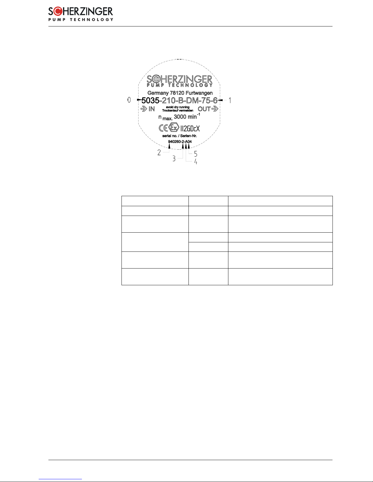
1.11 Identification based on the example of the pump type 5035-210-B-DM-75-6 . . . . . . . . . . . . . . 13
1.12Intendeduse/normaloperation....................................... 13
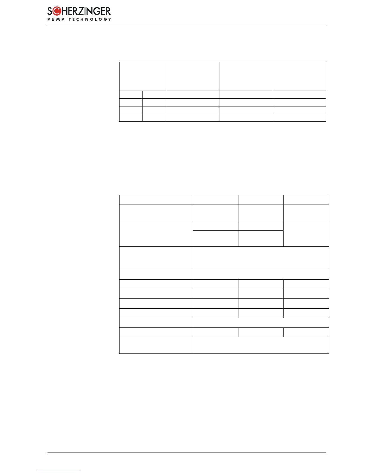
1.12.1 Limitvalues............................................. 14
1.12.2 Temperature classes and approved temperatures . . . . . . . . . . . . . . . . . . . . . . . 15
1.12.3 Overview of series/wetted parts . . . . . . . . . . . . . . . . . . . . . . . . . . . . . . . . . 15
1.12.4 Paint ................................................ 16
1.12.5 Maximumpossiblespeed..................................... 16
1.13Improperuse/fault.............................................. 17
1.13.1 Dangerfromdust ......................................... 17
1.13.2 Danger from dry running of the pump . . . . . . . . . . . . . . . . . . . . . . . . . . . . . . 18
1.13.3 Danger from overheating of the pump . . . . . . . . . . . . . . . . . . . . . . . . . . . . . . 18
1.13.4 Danger from overpressure in the pump . . . . . . . . . . . . . . . . . . . . . . . . . . . . . 19
1.13.5 Danger from particles/foreign matter in the fluid . . . . . . . . . . . . . . . . . . . . . . . . . 20
1.13.6 Danger from incorrect direction of rotation . . . . . . . . . . . . . . . . . . . . . . . . . . . . 20
1.13.7 Danger from operation with too high of a speed . . . . . . . . . . . . . . . . . . . . . . . . . 21
1.13.8 Danger from potential difference . . . . . . . . . . . . . . . . . . . . . . . . . . . . . . . . . 21
1.13.9 Danger from exceeding the maximum torque . . . . . . . . . . . . . . . . . . . . . . . . . . 21
1.13.10 Danger from mechanically produced sparks . . . . . . . . . . . . . . . . . . . . . . . . . . . 22
1.14Complaints.................................................. 23
1.15Warrantyandliability ............................................ 24
1.16Declarationofconformity .......................................... 25
1.16.1 Declaration of conformity as per Directive 2014/34/EU . . . . . . . . . . . . . . . . . . . . . 25
1.16.2 Declaration of conformity as per Directive 2006/42/EC (Machinery Directive) . . . . . . . . 26
1.16.3 CE conformity notes relating to fitting a motor/drive . . . . . . . . . . . . . . . . . . . . . . . 27
1.17Certificateofnon-objection......................................... 28
2 Safety Instructions 29
2.1 Dangerfrommovingmachineparts .................................... 29
2.2 Dangerfromhotparts............................................ 30
2.3 Dangerfromelectricshock ......................................... 30
2.4 Dangerfrommagneticfields ........................................ 31
2.5 Dangerfromfluids.............................................. 32
3 Transport and interim storage 33
3.1 Shipping of the pump and protective measures . . . . . . . . . . . . . . . . . . . . . . . . . . . . . . 33
3.2 Interimstorage................................................ 33
3.3 Conserving the machine for storage after operating/flushing the pump . . . . . . . . . . . . . . . . . 34
3.4 Returntothefactory............................................. 34
4 Mode of operation/Functional description 35
4.1 Pumpfunction ................................................ 35
OI Pump Edition 4.3 3

Table of contents
4.2 Constructivedesignofthepump...................................... 36
4.2.1 Pumpbody............................................. 36
4.2.2 Design and commissioning of pressure relief valve (only for 50X5-...-B-...) . . . . . . . . . . 39
4.2.3 Magneticcoupling ......................................... 42
4.2.4 Bearingbushes .......................................... 43
5 Installation/Dismantling 45
5.1 Information about the installation location . . . . . . . . . . . . . . . . . . . . . . . . . . . . . . . . . 45
5.2 Firstinstallation ............................................... 45
5.3 Installationposition ............................................. 46
5.4 Installation of the magnetic coupling . . . . . . . . . . . . . . . . . . . . . . . . . . . . . . . . . . . . 47
5.5 Installation/dismantling of motor flange and drive unit . . . . . . . . . . . . . . . . . . . . . . . . . . 48
5.6 Connectionpipes .............................................. 49
6 Commissioning/Decommissioning 53
6.1 Requirementforcommissioning ...................................... 53
6.2 Commissioning ............................................... 53
6.3 Monitoring .................................................. 54
6.4 Decommissioning .............................................. 55
6.5 Removalfromthesystem.......................................... 55
7 Maintenance/Cleaning 57
7.1 Generalinformation ............................................. 57
7.2 Safety instructions for maintenance, inspection and installation work . . . . . . . . . . . . . . . . . . 57
7.3 Maintenancecycle.............................................. 58
7.4 Externalcleaningofthepump ....................................... 58
7.5 Cleaning of the pump for use in special areas . . . . . . . . . . . . . . . . . . . . . . . . . . . . . . . 59
8 Faults, causes and rectification 61
9 Components 65
9.1 Componentslist ............................................... 65
10 Technical Data 68
10.1 Connection dimensions at motor end . . . . . . . . . . . . . . . . . . . . . . . . . . . . . . . . . . . 68
10.1.1 PKdesign ............................................. 68
10.1.2 MKdesign ............................................. 68
10.1.3 ZKdesign.............................................. 68
10.2 Connection dimensions at pump end and motor connection . . . . . . . . . . . . . . . . . . . . . . . 70
10.2.1 Motor design with connection in accordance with DIN ISO 228 or ANSI B1.20.1 . . . . . . 70
10.2.2 Motor design with connection for SAE-ISO 6162-1 . . . . . . . . . . . . . . . . . . . . . . . 70
10.2.3 Motor design with flange EN 1092-1 . . . . . . . . . . . . . . . . . . . . . . . . . . . . . . . 70
10.3Soundpressurelevel ............................................ 72
10.4Non-ionizingradiation............................................ 72
11 Disposal 73
11.1Disposalofthefluid ............................................. 73
12 Appendix 75
12.1Listofrevisions ............................................... 75
12.2Signaturelist................................................. 75
4 OI Pump Edition 4.3

1 Introduction
1 Introduction
1.1 Preface
These operating instructions from Firma Scherzinger Pumpen GmbH & Co.
KG form part of the pump.
The operating instructions are intended for everyone who undertakes assembly, in-
stallation, commissioning, and service work on the pump.
Please read the operating instructions through carefully, taking particular note
of the safety instructions!
Should you have any questions with respect to the pump, its application range or in
case of any other questions, our employees are always available and will assist you
personally.
1.2 Product identification/Product information
Validity
The descriptions in these operating instructions refer exclusively to the pump as
described in the technical data (⇒Chapter 10 on page 68) and as it was developed
and built by the manufacturer.
Product information
The pump from Firma Scherzinger Pumpen GmbH & Co. KG is suited to pumping
liquids, which do not have a corrosive or aggressive effect on the materials used (⇒
Chapter 1.12.3 on page 15).
Other valid documents
Other valid documents are documents that are not included in the operating instruc-
tions but are also supplied with them. If one of the documents mentioned below is
missing, please contact the manufacturer. Other valid documents are:
- Technical documentation/operating instructions of the motor manufacturer,
- Motor manufacturer’s certificate from the Physikalisch-Technische Bundesanstalt
(PTB),
- Optional: Technical documentation of the accessories.
If you are a mechanic or use/operate the machine, you must have read and under-
stood the other valid documents prior to installing and commissioning the machine.
Make sure that these documents are always available on site near the machine.
1.3 Storage
The operating instructions for the pump must always be stored close to it and be
within easy reach when needed.
OI Pump Edition 4.3 5

1 Introduction
1.4 Definition of terms
In the following section, any fluid to be transported will be called „fluid“ whatever its
type.
These operating instructions are valid for the pump series:
5035
5045
5055
To make things clearer, the 5035, 5045 and 5055 series are identified below as 50X5.
The 50X5 pump series are available in the following designs:
- Motor design comprising: Pump head, magnetic coupling case, motor flange, and
motor.
- ZK design comprising: Pump head, magnetic coupling case, and motor flange.
- MK design comprising: Pump head and magnetic coupling case.
- PK design comprising: Pump head.
⇒Chapter 4.2.1 on page 36
For precise details of your pump, please consult your order documentation.
1.5 Offices abroad
A list of our worldwide offices, including addresses, can be obtained from the manu-
facturer’s factory or found online at www.scherzinger.de.
In most instances, these offices are sales branches which, to some extent, also carry
out repair and maintenance work. However, this work is preferentially carried out in
the main plant in Furtwangen.
6 OI Pump Edition 4.3

1 Introduction
1.6 Symbols used in this manual
1.6.1 Danger warning levels
DANGER!
Texts marked with DANGER! warn of exceptionally great and acute hazards.
These hazards will inevitably result in serious (irreversible) injuries or even
death if no preventative countermeasures are taken!
It is imperative that these texts are observed and preventative countermea-
sures taken!
WARNING!
Texts marked with WARNING! warn of exceptionally great and acute hazards.
These hazards will inevitably result in serious (irreversible) injuries or even
death if no preventative countermeasures are taken!
It is imperative that these texts are observed and preventative countermea-
sures taken!
CAUTION!
Texts marked with CAUTION! warn of eventually dangerous situations. These
situations will inevitably result in slight to moderate (irreversible) injuries if no
preventative countermeasures are taken!
It is imperative that these texts are observed and preventative countermea-
sures taken!
ATTENTION!
Texts labeled with ATTENTION! contain important notes about situations
which, if the appropriate preventative countermeasures are not taken, could
possibly damage the product and/or its functions or materials located in the
immediate vicinity.
It is imperative that these texts are observed and preventative countermea-
sures taken!
Texts labeled with this symbol contain very important instructions!
It is imperative that these texts are observed!
This symbol indicates texts which contain important instructions/comments
or tips.
OI Pump Edition 4.3 7

1 Introduction
1.6.2 Danger symbols
1.6.2.1 General danger symbol
Warning of dangers that result in serious (irreversible) injury or even death!
1.6.2.2 Specific danger symbols
Warning of dangerously hot surfaces!
Warning of mechanical movements or risk of hand injuries!
Warning of explosive substances!
Warning of a potentially explosive atmosphere!
Warning of flammable substances!
8 OI Pump Edition 4.3

1 Introduction
1.6.3 Command symbols
Note the documentation and information provided!
Switch off the pump (release)!
Wear ear defenders!
Wear protective gloves for protection against thermal risks as per EN 407!
Wear protection class 1 safety shoes!
Wear respiratory protection!
Wear safety glasses!
The actual definition of personal protective equipment depends on the fluid
being transported and the cleaning agent used. It must be specified by the
operator!
OI Pump Edition 4.3 9

1 Introduction
1.6.4 General symbols
•This dot designates the description of activities to be performed.
-This dash designates numerations.
⇒This arrow designates cross-references.
For purposes of clarity, abbreviations are used if cross-references to other chapters
are made in the text.
Example: ⇒2 Safety instructions
This means: Refer to Chapter 2 Safety instructions in this manual.
If the cross-reference refers to a page, figure or item number, this information will be
provided at the end of the cross-reference.
Example: ⇒Fig. 4 - 4, 1
This means: refer to item number 1 in Figure 4 (in this manual in Chapter 4).
(3) Numbers in parentheses refer to items within the figures.
1.7 Personal protective equipment
The personal protective equipment suggested in these operating instructions only
applies to this particular pump. The requirements for personal protective equipment
arising from local environmental conditions, other products, or the use with other
products, are not described in these operating instructions, and must be adapted to
the actual risks by the operator.
The actual definition of personal protective equipment depends on the fluid
being transported and the cleaning agent used. It must be specified by the
operator!
1.8 Definition of qualified/authorized personnel
Bodily injury or material damage may result from unqualified operations of the pump.
For this reason, only qualified personnel may operate the pump, commission and
decommission it, clean and maintain it.
In this sense, qualified personnel are those persons who:
- are familiar with the safety concepts of the pump.
- are trained as operating personnel with respect to the handling of the pump, and
who are familiar with the contents of the operating instructions regarding operation
and servicing.
- have received appropriate instruction from qualified personnel.
- because of their education, experience and training as well as knowledge of ap-
plicable standards, provisions, accident-prevention regulations, explosion protec-
tion and operating conditions, have received authorization from the supervisor
responsible for the safety of the pump to perform the necessary activities and to
recognize and prevent potential hazards.
10 OI Pump Edition 4.3

1 Introduction
1.9 Obligations of the operator
The operator undertakes to let only experts work with this pump who
•have been sufficiently trained to perform the activities in question.
•are acquainted with the fundamental regulations on safety and accident preven-
tion in the workplace and explosion protection, and have received qualified in-
struction in the handling of the pump.
•have read and understood the safety and warning instructions contained in these
operating instructions.
In the interests of all involved, please take note of the following instructions:
•In addition to these operating instructions, please make available all generally
valid statutory and other relevant binding regulations regarding safety and acci-
dent prevention in the workplace, environmental protection and explosion protec-
tion, and instruct the personnel who will be working with the pump regarding these
regulations!
•Amend these operating instructions with instructions regarding operational par-
ticularities such as those related to work organization, process flows, authorized
personnel (including obligatory supervision and registration)!
•Clearly establish the specific responsibilities of the personnel for operation, clean-
ing, maintenance, etc.!
•Check at regular intervals that the personnel are working in a safety and risk-
conscious manner!
•Implement measures that ensure that the pump is only operated in a safe and
fully functional condition!
•Ensure the pump is cleaned and maintained within the specified intervals (⇒
Chapter 7.3 on page 58)!
•Do not make any structural changes (with the exception of those described in the
operating instructions) without prior written consent from the manufacturer!
•Implement stringent provisions, to ensure that personnel who have not been in-
structed on the basis of the safety instructions and the residual risks which may
arise when working on or with the pump, do not enter the hazard area of the
pump!
•At surface temperatures above 50 °C, a warning sign must be placed on the ma-
chine in a clearly visible position. When surface temperatures exceed 80°C, insu-
lation will be required, or the area must be enclosed/demarcated at an adequate
distance from the source of danger.
•Securing the working environment is solely the operator’s responsibility.
OI Pump Edition 4.3 11

1 Introduction
1.10 Obligations of the Personnel
All persons authorized to work with the pump are obliged, before commencing
work
- to observe the fundamental regulations on safety and accident prevention
at the workplace.
- to read the safety and warning instructions in this documentation.
In the interests of all involved, please take note of the following instructions:
•Do not use any working methods that are questionable in terms of safety!
•Observe all hazard and warning signs in these operating instructions!
•In addition to these operating instructions, comply with the generally valid
statutory and other relevant binding regulations regarding safety and acci-
dent prevention in the workplace, explosion protection and environmental
protection!
•Be aware of potential fire detection and fire-fighting equipment, locate fire
extinguishers and find out how to operate them!
•Wear adequate personal protective equipment suitable for the work you
have to carry out!
•Tie back and secure any long hair. Do not wear loose clothing or jewelry
(including rings)!
•Only perform tasks for which you have received the appropriate training!
•Do not allow any repair work to be carried out, without first contacting the
manufacturer and an authorized representative of the operating company!
•Do not make any structural changes (with the exception of those described
in the operating instructions) without prior written consent from the manu-
facturer!
•Take steps to ensure that other people, who are not working on the pump
and therefore do not know the potential risks of the pump, cannot access
the hazard areas of the machine.
•In the event of a safety hazard, decommission the pump! Secure the pump
against being accidentally switched back on and notify the operator imme-
diately!
12 OI Pump Edition 4.3

1 Introduction
1.11 Identification based on the example of the pump type 5035-210-B-DM-75-6
0Series
1Type designation
2Production no.
3Quantity
4Year
5Month
Figure 1.11-1: Type plate for pump with motor
Equipment group II Above ground working
Category 2 / 3 High degree of safety
Zones 1 and 21
2 and 22
Occasional danger of explosion
Rare danger of explosion
Atmosphere G Gas
D Dust
Ignition protection
category
c Constructional safety
Explosion group
Temperature class
X Not applicable. Observe the notes
within the operating instructions.*
*Specify the temperature class(es) in the device only if the resulting surface tem-
perature is of the device itself is determined (according to DIN EN 80079-36). This
means that the temperature of pump surfaces is determined by the fluid in the case
of normal operation.
1.12 Intended use/normal operation
The sole use of the pump defined in the technical data is for the transportation of
low to medium viscous particle-free media that have degreasing to well-lubricating
characteristics, that do not have a corrosive or aggressive effect on the materials fed
into the pump. They are suitable for the transport of alkaline as well as acid fluids.
The resistance of the materials stated below should be noted!
The pump is only:
- for use within permanent buildings,
- for commercial use,
- for transporting fluids,
- for use by authorized personnel,
- for use by persons with a minimum age of 16 years.
OI Pump Edition 4.3 13

1 Introduction
The operator as well as the operating and maintenance and repair personnel are
required to have an adequate understanding of one official language.
The pump is not designed for use in a radioactive or biologically contaminated atmo-
sphere!
The components/wear parts to be used must have been approved by the manufac-
turer for this purpose.
1.12.1 Limit values
Intended use can be ensured by observing the following limit values:
Description Value
Max. differential pres-
sure rise
Max. 20 bar, depending on material combination and
medium
Max. system pressure
(pressure side)
40 bar with 50X5-130-... and variant in accordance with
EN 1092
100 bar with other types
Max. suction vacuum 0.9 bar (filled with fluid)
Operating tempera-
ture
-20 to 120°C
-20 to 70°C with PTFE gears/bearings
Ambient temperature -40 to 60 °C depending on the materials and
attachments
Viscosity range 0.5 to 10,000 2/s
Speed range 0 to 3000 rpm (Dependent on the gear material)
Sound pressure level < 80 dB(A) determined at:
Rotation speed: 1500 rpm
Operating pressure: 10 bar
Operating temperature: 20 °C
Fluid: 1 mm2/s, non-lubricating
⇒Chapter 10.3 on page 72
Dimensions observe the respective data sheets
⇒Chapter 10 on page 68ff
Attachments observe applicable/supplied documents
(motor, PT100, etc.)
Electrical properties observe applicable/supplied documents
(motor, PT100, etc.)
Max. torque of cou-
pling
14 Nm
Due to the versatile combination possibilities in terms of the different sizes, gears,
motor speeds and electrical properties, an illustrative and clear representation of the
normal operation of all pumps in the respective variants is not possible. In this case,
please refer to the respective order documentation.
Any other use beyond the intended use described in the operating constructions is
deemed improper.
14 OI Pump Edition 4.3

1 Introduction
1.12.2 Temperature classes and approved temperatures
Temperature class Switch-off temperature
when Tmax of magnetic
coupling is reached
Switch-off temperature
when Tmax of fluid is
reached
Switch-off temperature
when Tmax of pump
surface on
containment can is
reached
T3*200°C 150°C*150°C*150°C*
T4 135°C 85°C 85°C 85°C
T5 100°C 50°C 50°C 50°C
T6 85°C 35°C 35°C 35°C
*Due to the magnetic material NdFeB, the design-related switch-off temperature is
+150°C
1.12.3 Overview of series/wetted parts
The 5035, 5045 and 5055 series only differ in terms of the different combinations of
materials.
5035 5045 5055
Casing [1], [2], [11], [12],
[31]
1.4404 Hastelloy C4 Titanium
Shafts [3], [4] 1.4571 Hastelloy C4 Titanium
1.4571/Cr2O3Hastelloy
C4/Cr2O3
Gears [5], [6] Nitronic 60 (N6),
Waukesha 88 (W8),
1.4528 hardened (SS)
Bearing [20] SSiC
Magnetic coupling hub [8] 1.4571 Hastelloy C4 Titanium
Clamp screw [38] 1.4571 Hastelloy C4 Titanium*3
Valve piston [35] 1.4571 Hastelloy C4 Titanium*3
Adjustment screw [39] 1.4404 Hastelloy C4 Titanium*3
Seals [29], [30], [34], [37] PTFE
Compression spring [36] 1.4310 Hastelloy C4 Titanium*3
Fluid Note the resistance of the materials mentioned
above.
*3 Not available for design with pressure relief valve!
OI Pump Edition 4.3 15

1 Introduction
1.12.4 Paint
All pumps are delivered from the plant without external painting/coating. However, if
a surface coating is desired, attention should be paid to the following note.
DANGER!
If it is necessary to use an external surface coating, ensure the following to
prevent dissemination of brush discharges: the total thickness of the paints
used does not exceed 2 mm in conjunction with the intended classification in
explosion class IIA and IIB and 0.2 mm with IIC.
1.12.5 Maximum possible speed
The maximum possible speed depends on the gear materials,
PEEK mod. 2800 rpm PTFE 2500 rpm
as well as the fluid viscosity:
1Max. pump speed (rpm)
2Fluid viscosity (mm2/s)
Figure 1.12-1: Viscosity range
DANGER!
If one or more limit values described in this section are exceeded, you have to
ask the manufacturer’s plant if these operating conditions are released by the
manufacturer. Otherwise, a modification of the pump must be carried out in
your case, because the pump or the system in which the pump is integrated
can be damaged or destroyed and present a danger for personnel.
16 OI Pump Edition 4.3

1 Introduction
1.13 Improper use/fault
Deviations from normal operation are to be defined as faults.
Predictable faults can be defined as follows:
- Partial or complete dry running (caused by e.g. closed fittings, clogged filters...)
- Large impurities in the fluid (>50µm) (such as beads of sweat, deposits from
tanks, sediments ...)
- Incorrect direction of rotation
- Pressure overload (caused by e.g. closed fittings, faulty components ...)
The partly listed faults refer to the potential ignition sources in accordance with the
ATEX directive as well as EN1127-1. The most relevant types of ignition sources for
gear pumps from Scherzinger are "hot surfaces", "mechanically generated sparks"
and "static electricity”.
There must not be any ferritic components in the fluid when operating the pump (with
magnetic coupling).
ATTENTION!
If improper use cannot be ruled out with certainty, the operator must put ap-
propriate monitoring measures in place!
1.13.1 Danger from dust
DANGER!
When operating the pump in a dusty environment, the danger of overheating
and spontaneous ignition arises.
•Protect the pump from dust using appropriate measures. Take care that the
air circulation is sufficient in order to avoid overheating of the pump.
•Remove dust deposits from the pump surface, the drive and the connection
pipes on a regular basis in order to avoid the creation of ignition sources.
The cleaning interval is determined by the amount of dustfall.
•Clean the pump as described ⇒Chapter 7.4 on page 58. Observe the man-
ufacturer’s specifications!
OI Pump Edition 4.3 17

1 Introduction
1.13.2 Danger from dry running of the pump
DANGER!
Without fluid, the pump runs dry. As the sliding surfaces are not lubricated
the gears and bearing bushes become hot and are thermally and mechanically
destroyed.
If there is no fluid in the containment can, the heat induced by eddy current
losses can also not be dissipated, resulting in the overheating of the pump.
On the suction side, the fluid to be distributed must always be present in order
to avoid temperature rises above the maximum permissible temperature (⇒
Chapter 1.12.1 on page 14).
Dry running protection
When the pump is operated, the interior of the pump must always be filled with
fluid. In this way, no explosive atmosphere can develop. If this cannot be en-
sured by the operator, we recommend monitoring measures for this purpose:
- Level switch in the container or the feed pipe,
- Flow monitor at the pump inlet,
- Monitoring of the drive performance,
- TARGET/ACTUAL comparison at the pump output.
1.13.3 Danger from overheating of the pump
DANGER!
Overload, overheating or non-observance of normal operation can lead to an
inadmissibly high temperature rise. This only serves as short-term overload
protection for designs with a pressure relief valve. When opened for longer,
there is the danger of the pump head being damaged or destroyed by over-
heating. The surface temperature can exceed critical values.
Temperature monitoring
We recommend monitoring measures for this purpose:
- With resistance thermometers at critical pump components such as depositories
in the cover.
- With resistance thermometers at critical pump components such as the surfaces
of the magnetic coupling case.
18 OI Pump Edition 4.3

1 Introduction
1.13.4 Danger from overpressure in the pump
DANGER!
An operation with closed shut-off devices suction/pressure pipe is not permit-
ted! Due to closed shut-off devices or closed pipes, there is the risk of very
high surface temperatures, after even a short period of time, caused by fluid
overheating in the interior of the pump.
Overpressure protection
If the pump is not equipped with an integrated pressure relief valve, we rec-
ommend monitoring measures for this purpose:
- Overflow valve,
- Pressure switch,
- Monitoring of the drive performance,
- Temperature monitoring.
If the pump is operated against a closed system, the pump will heat up. Measure-
ments have shown a temperature input of 80°K within 4 minutes (2500 rpm, opening
pressure 7 bar, closed pressure pipe).
Under these operating conditions, the surface temperature must be monitored. You
must switch the pump off at least at 50°K below the maximum permissible surface
temperature as the surface temperature can still rise in a time-delayed manner after
being switched off.
The following diagram shows the increase of the pump surface temperature at a
closed pressure pipe and permanent circulation via the internal pressure relief valve.
The fluid temperature at the beginning of the measurement was ambient temperature
(20°C).
1Surface temperature rise (K)
2Time (min)
Figure 1.13-1: Temperature rise
If the ambient temperature is higher than the fluid temperature, the surface tempera-
ture rise can be even higher!
OI Pump Edition 4.3 19

1 Introduction
1.13.5 Danger from particles/foreign matter in the fluid
DANGER!
Inadmissible operating conditions can arise from foreign matters in the fluid
and result in the premature wear of pump components, so that very high sur-
face temperatures can develop after a short time.
Prefilter
We recommend the following monitoring measures:
- Filter with contamination indicator.
- Filter with depression and differential pressure monitoring.
1.13.6 Danger from incorrect direction of rotation
DANGER!
Operating the pump in the opposite direction of rotation can result in the
increase of the resistance on the suction side.
The counter-pressure cannot be relieved. The pump performance is therefore
converted to heat. Furthermore, the fluid on the pressure side can be emptied,
resulting in the danger of dry running (⇒Chapter 1.13.2 on page 18).
This can lead to an inadmissible increase of the surface temperature and fire
risk.
In both cases, there is a danger of an inadmissible heating of the pump. On
the back of the pump, the direction of rotation as well as the connections are
marked.
Rotation direction control
If the explosive atmosphere is also present during the installation phase, the
rotation direction cannot be controlled by shortly switching on the unfilled
pump in order to avoid an inadmissible temperature rise. We recommend the
following monitoring measures:
- Rotation direction control only at filled pump.
- Rotation direction control with rotary field instrument.
20 OI Pump Edition 4.3
This manual suits for next models
2
Table of contents
Other Scherzinger Water Pump manuals
Popular Water Pump manuals by other brands

Gardena
Gardena 19500 AquaSensor Operator's manual

Varian
Varian triscroll 600 Installation and operation manual

Crane
Crane Barnes 3SE-L Series Installation and operation manual

Lincoln
Lincoln Pile Driver III D Series Assembly

DURAVIT
DURAVIT SensoWash 1007150000 Service instructions

Intex
Intex Quick-Fill 58609 Operation instructions

Ingersoll-Rand
Ingersoll-Rand ARO PD20 Series Operator's manual

Met-Pro
Met-Pro Fybroc 3306-24 installation manual

Graco
Graco Husky 715 Instructions and parts list

Grundfos
Grundfos MAGNA 2000 Series Installation and operating instructions

Bestway
Bestway 58614E owner's manual

Walrus
Walrus TS400C instruction manual