manuals.online logo
Brands
  1. Home
  2. •
  3. Brands
  4. •
  5. MasterCraft
  6. •
  7. Water Pump
  8. •
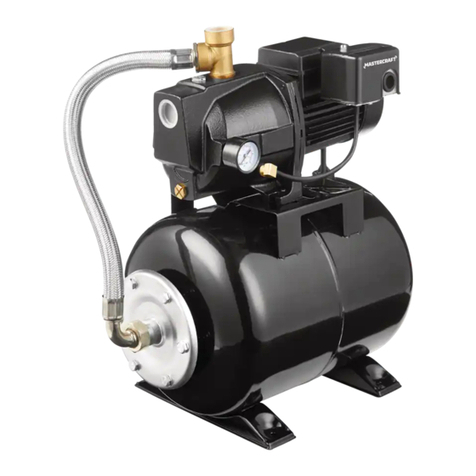
  9. MasterCraft 062-3593-2 User manual

MasterCraft 062-3593-2 User manual

headline bars
continuation tabs
notes
warnings
IMPORTANT:
Please read this manual carefully before running this
jet pump and save it for reference.
INSTRUCTION
MANUAL
SHALLOW WELL
JET PUMP
WITH ELECTRONIC PRESSURE CONTROL
9
Model No. 062-3593-2
headline bars
continuation tabs
notes
warnings
headline bars
continuation tabs
notes
warnings
headline bars
continuation tabs
notes
warnings
3
headline bars
continuation tabs
notes
warnings
headline bars
continuation tabs
notes
warnings
NOTE:
If any parts are missing or damaged, or if you have any questions, please call our
toll-free helpline at 1-800-689-9928.
SAVE THESE INSTRUCTIONS
This manual contains important safety and operating instructions.
Read all instructions and follow them with use of this product.
TABLE OF CONTENTS
Quick Start Guide 4
Technical Specifications 6
Safety Guidelines 8
Important Information 11
Key Parts Diagram 12
Assembly Instructions 13
Operating Instructions 17
Troubleshooting 18
Warranty 19
TABLE OF CONTENTS
headline bars
continuation tabs
notes
warnings
headline bars
continuation tabs
notes
warnings
model no. 062-3593-2 | contact us 1-800-689-9928
4
QUICK START GUIDE
Prime the pump.
2
Connect the pump outlet to the water
system in your house. Plug the pump
into 115 V GFCI outlet.
3
Connect the suction pipe to the pump
inlet.
1
Max. 25' (7.6 m)
Foot
valve
Check valve
Pipe
SHALLOW WELL INSTALLATION
headline bars
continuation tabs
notes
warnings
5
headline bars
continuation tabs
notes
warnings
QUICK START GUIDE
Connect all the pipe lines as the
diagram shows, then turn on the faucet
and all the ball valves and allow water
flow. When a steady stream of water
flows out of the faucet, close the faucet
and the ball valve in the main water
supply line. Plug the pump into 115 V
GFCI outlet.
1
Typical bypass piping needed to
allow removal of pump for repair
without shutting down household
water system. Turn on the ball valve
in the main water supply line, and
close the two ball valves in both the
pump outlet and inlet.
2
Unions
To household
(pump discharge)
Grounded, GFCI
protected
115 V outlet
Water supply in
(pump suction)
Check valve
TYPICAL HOUSEHOLD BOOSTER INSTALLATION
Unions
To household
(pump discharge)
Water supply in
(pump suction)
Check valve
headline bars
continuation tabs
notes
warnings
headline bars
continuation tabs
notes
warnings
model no. 062-3593-2 | contact us 1-800-689-9928
6
TECHNICAL SPECIFICATIONS
Temperature 32 to 77ºF (0 to 25ºC)
Impeller Plastic
Solids handling 0” (0 mm) spherical
Discharge /suction size 1” (2.5 cm) national pipe thread (NPT)
Seal Mechanical seal
Upper bearing Ball bearing
Lower bearing Ball bearing
Single phase Permanent split capacitor (PSC)
Motor protection Auto-reset thermal overload protection in motor
Construction material Aluminum alloy for motor house: plastic for diffuser and
impeller; stainless steel for pump body
Motor NEMA L, torque curve, squirrel cage induction,
class B insulation
MOTOR AND ELECTRICAL
SKU number 062-3593-2
HP 3/4
Volt 115
Hz 60
RPM 3450
Full load amps 8
NOTE:
The suction pipe size should not be less than 1” (2.5 cm). The suction size of
this pump is 1” (2.5 cm) national pipe thread (NPT).
headline bars
continuation tabs
notes
warnings
7
headline bars
continuation tabs
notes
warnings
TECHNICAL SPECIFICATIONS
DIMENSIONS
PERFORMANCE CHART
TECHNICAL SPECIFICATIONS
Temperature 32 to 77ºF (0 to 25ºC)
Impeller Plastic
Solids handling 0” (0 mm) spherical
Discharge /suction size 1” (2.5 cm) national pipe thread (NPT)
Seal Mechanical seal
Upper bearing Ball bearing
Lower bearing Ball bearing
Single phase Permanent split capacitor (PSC)
Motor protection Auto-reset thermal overload protection in motor
Construction material Aluminum alloy for motor house: plastic for diffuser and
impeller; stainless steel for pump body
Motor NEMA L, torque curve, squirrel cage induction,
class B insulation
Lift height 0’
(0 m)
5’
(1.5 m)
10’
(3 m)
15’
(4.6 m)
20’
(6 m)
25’
(7.6 m)
Gallons per hour
Litres per hour
600
(2271)
564
(2135)
528
(1999)
480
(1817)
408
(1544)
324
(1226)
17 1/16" (43.4 cm)
10 11/16" (27.1 cm)
15 3/8" (39.1 cm)
7 1/4" (18.4 cm) 8 15/16" (22.7 cm)
5 5/16" (13.5 cm)
8 13/16" (22.4 cm)
3 13/16" (9.7 cm)
All performances shown at 30 PSI discharge pressure.
headline bars
continuation tabs
notes
warnings
headline bars
continuation tabs
notes
warnings
model no. 062-3593-2 | contact us 1-800-689-9928
8
SAFETY GUIDELINES
This manual contains information that relates to protecting personal safety and preventing
equipment problems. It is very important to read this manual carefully and understand it
thoroughly before using this product.
• These precautions are intended for the personal safety of the operator and others working
with the operator. Failure to follow these instructions may result in a permanent loss of vision,
serious personal or even fatal injury, property damage and/or tool damage. Please take the time
to read and understand them.
• Wear safety glasses with side shields when operating the pump and verify that others in the
work area are also wearing safety glasses. Safety glasses must conform to both American
National Standards Institute (ANSI Z87.1) and Canadian Standards Association (CSA Z94.3)
standards requirements and must provide protection from flying particles from the front and the
sides. Failure to comply may result in moderate injury.
• The motor of this pump has a thermal protector that will trip if the motor becomes too hot. The
protector will reset itself once the motor cools down and an acceptable temperature has been
reached. The pump may restart unexpectedly if it is plugged in.
• This pump is made of high-strength, corrosion-resistant materials. It will provide trouble-free
service for a long time when properly installed, maintained, and used. However, inadequate
electrical power to the pump, dirt, or debris may cause the pump to fail. Please carefully read
the manual and follow the instructions regarding common pump problems and remedies.
• Mastercraft Canada is not responsible for losses, injury, or death resulting from a failure to
observe these safety precautions, or the misuse or abuse of pumps or equipment..
DANGER!
• Keep children away from the work area. Do not allow children to handle the pump.
• Follow all electrical and safety codes, particularly the Canadian Electrical Code, and local codes and ordinances.
• Disconnect the power supply to the pump, drain all water and release all pressure from the water system before
servicing any pump component.
• Risk of fire or explosion: Do not pump flammable or explosive liquids such as oil, gasoline, kerosene, ethanol, etc. Do not
use in the presence of flammable or explosive vapours. Using this pump with or near flammable liquids can cause an
explosion or fire, resulting in property damage, serious personal injury and/or death.
• Risk of electric shock: Never remove the ground terminal on the three-pronged power plug of the pump as the ground
terminal is designed for protection. Do not adjust any electrical appliance or product without disconnecting the power
supply. Do not stand on wet or damp surface or in water when the pump is connected. Avoid handling the pump with
wet hands.
• Risk of burns: Do not touch the motor housing during operation. The motor is designed to operate at high temperatures.
Do not disassemble the motor housing
• Ensure the electrical power source is adequate for the requirements of the pump.
• Extension cords may not deliver sufficient voltage to the pump motor. Extension cords present a life-threatening safety
hazard if the insulation becomes damaged or the connection ends fall into water. The use of an extension cord to power
this pump is not permitted.
• Ensure that the electrical circuit to the pump is protected by a 20-amp or larger fuse or circuit breaker.
CAUTION!
• Know the pump and its applications, limitations, and potential hazards.
• Secure the discharge line before starting the pump. An unsecured discharge line will whip, possibly causing personal
injury and/or property damage.
• Secure the pump to a solid base. This will aid in keeping the pump in a vertical orientation. This is critical in keeping the
pump operating at maximum efficiency. It will also help prevent the pump from clogging resulting in premature failure.
• Periodically inspect the pump and system components. Disconnect the pump from the power supply before inspecting.
• Never run the pump dry, as doing so may damage the mechanical seal and void the warranty. This pump has to be
primed before starting.
SAFETY GUIDELINES
headline bars
continuation tabs
notes
warnings
9
headline bars
continuation tabs
notes
warnings
UNPACKING
• Upon receiving the pump, it should be inspected for damage or shortages. If damage has
occurred, file a claim immediately with the carrier that delivered the pump. If the manual is
removed from the packaging, do not lose or misplace.
STORAGE
• Short Term—Pumps are manufactured for efficient performance following short inoperative
periods in storage. For best results, pumps can be retained in storage, as factory assembled,
in a dry atmosphere with constant temperatures for up to six (6) months.
• Long Term—For storage of six (6) months, to twenty-four (24) months, the units should
be stored in a temperature-controlled area, a roofed-over, walled enclosure that provides
protection from the elements (rain, snow, wind-blown, dust, etc.), and whose temperature
can be maintained between 4 and 40°C (40 and 120°F). If extended high humidity is
expected to be a problem, all exposed parts should be inspected before storage and all
surfaces that have the paint scratched, damaged, or worn should be recoated with a water-
based, air-dry enamel paint. All surfaces should then be sprayed with a rust-inhibiting oil.
• Pump should be stored in its original shipping container. On initial start up, rotate impeller by
hand to assure seal and impeller rotate freely.
INSTALLATION
SUCTION
• All joints and connections must be AIRTIGHT. A single leak will prevent the proper operation
of the pump. Wrap thread tape clockwise on all threaded connections. For all non-threaded
connections, you must use PVC Purple Primer and PVC Cement to ensure airtight seals.
Measure all pipe lengths before attaching.
• A foot valve is a check valve that is used to keep the water from running back into the well
from the pump and maintain hydraulic pressure when the pump is not running. If the foot
valve does not hold the water the pump will lose it’s prime and will not pump water. If the
foot valve open pressure is too high (the spring is too stiff), or the flow area is too small, the
pump suction head and flow rate will significantly drop.
ELECTRICAL CONNECTIONS
• Plug the pump into a 115 V, 60 Hz, Ground Fault Circuit Interrupter (GFCI) protected grounded
outlet only. The pump is equipped with a 3-wire grounded cord and plug. Do not modify or
remove the plug. Make sure the outlet meets the National Electric Code or the Canadian
Electrical Code, as applicable. To avoid dangerous electrical shock hazard, keep the cord dry
at all times.
DANGER!
• Hazardous voltage. Risk of dangerous or fatal electric shock.
WARNING!
• Protect the electrical cord from sharp objects, hot surfaces, oil, and chemicals. Avoid kinking the cord. Do
not use damaged or worn cords.
• Failure to comply with the instructions and designed operation of this unit may void the warranty.
Attempting to use a damaged pump can result in property damage, serious personal injury and/or death.
SAFETY GUIDELINES
headline bars
continuation tabs
notes
warnings
headline bars
continuation tabs
notes
warnings
10
model no. 062-3593-2 | contact us 1-800-689-9928
SAFETY GUIDELINES
WIRE SIZE
• Consult a qualified electrician for proper wire size.
PRE-OPERATION: CHECK VOLTAGE AND PHASE
• Before operating pump, check to make sure that the voltage and phase information
stamped on the pump’s identification plate matches the available power.
IDENTIFICATION PLATE
• Note the numbers on the pump’s identification plate and record at the end of the manual
for future reference.
INSULATION TEST
• Before the pump is put into service, an insulation (megger) test should be performed on it.
The ohm values as well as the volts and amps should be recorded.
PUMP TEST
• After the pump has been properly wired and primed, it is advisable to check the system
by filling with liquid and allowing the pump to operate through its pumping cycle.
• An automatic pressure controller has been installed on the pump. The automatic pressure
controller allows for automatic operation.
MAINTENANCE
• No other maintenance is required.
SAFETY GUIDELINES
headline bars
continuation tabs
notes
warnings
11
headline bars
continuation tabs
notes
warnings
IMPORTANT INFORMATION
GENERAL USE
• Pump only clean water with your pump. To avoid clogging the pump and damaging the
shaft seal, do not pump water containing solids, foreign material, sand, silt, or abrasives.
• If you are boosting the pressure from a well pump, be sure that the system check valves
are tight. If the system pressure drops when the well pump is not running, the pump
may start and cycle. Excessive or rapid cycling may damage the motor and will void the
warranty.
• Do not use pipe joint compound on pump ports; use only PTFE tape to seal the threads.
Pipe joint compound will damage the controller materials.
• Tighten all the piping joints to the pump hand tight plus 1 1/2 turns (not more).
Overtightening may break the pump and will void the warranty.
• Pipe and fittings to the pump should be at least nominal 1” (2.5 cm) diameter. Pipe or
fittings less than 1” (2.5 cm) in diameter will reduce performance and may damage the
pump through cavitation.
• Make sure that there are no air leaks or air pockets in the suction pipe. An air leak in the
suction pipe may draw air in, although no water leaks out. Air leaks and air pockets will
prevent the pump from priming properly, and can substantially reduce its performance.
• The pump mount should be level, solid, as near as possible to the water source, and
protected against excess moisture and flooding.
• Use the shortest possible run for piping and the smallest possible number of fittings. Long
pipe runs and numerous fittings increase friction and reduce the flow of water.
• Support the weight of the piping and pump.
• Do not allow the pump, pressure controller, or any system components to freeze. Freezing
will damage the pump and void the warranty.
• Periodically inspect the pump, pressure controller, and system components.
CAUTION!
• Risk of leaks and flooding. Do not use this pump with inlet pressure less than 10 PSI (70 kPa) or
greater than 50 PSI (345 kPa).
WARNING!
• Pressure hazard and risk of explosion. This pump can develop high pressure when operated with
the discharge shut off or obstructed. For safe operation, we recommend the following:
If not already in the plumbing system, install a pressure relief valve in the pump discharge line
capable of passing the full pump flow at 100 PSI (689 kPa). If local code requires installation of a
pressure relief valve capable of handling the full pump flow at a pressure less than 100 PSI (689
kPa), follow the code requirements. Run the relief valve discharge to a floor drain or other drain
that will give adequate runoff.
NOTE:
The priming plug has an O-ring already installed and does not require sealing.
Local code may require a pressure relief valve or pressure regulator.
headline bars
continuation tabs
notes
warnings
model no. 062-3593-2 | contact us 1-800-689-9928
12
PARTS LIST
No. Description Qty.
1 Connector 1
2 Electronic control 1
3 Power cord 1
4 Plug 1
5 Priming elbow
No. Description Qty.
6 Pressure gauge 1
7 Pump body 1
8 Connection wire 1
9 Motor 1
1
2
4
5
7
6
3
8
9
KEY PARTS DIAGRAM
headline bars
continuation tabs
notes
warnings
13
ASSEMBLY INSTRUCTIONS
MATERIALS REQUIRED (NOT INCLUDED)
TOOLS REQUIRED
Flathead screwdriver
Thread tape
Hacksaw
Pipe wrench
Tape measure
PVC
PVC glue
Discharge tee Pipe
Threaded adaptor Elbow
Ball valve Check valve
Union
DETERMINE THE DEPTH OF YOUR WELL
Tie a small but heavy weight such as a fishing weight to the end of a piece of cotton string. Lower
the weight into the well until it reaches the bottom of the well. Make a mark on the string at ground
level. Pull the weight out of the well and measure from the bottom of the weight to the ground level
mark. This is the depth of your well. Subtract 5’ (1.5 m) from the depth of your well. If this number is
less than 25’ (7.6 m), shallow well installation should be used. If this number is more than 25’ (7.6
m) and less than 70’ (21.3 m), deep well installation should be used. If this number is more than 70’
(21.3 m), a deep well submersible pump should be selected. Measure the ground level mark to the
mark where the cotton string is wetted. This number is your well’s water level. The pump should
be at least 10’ (3 m) below the well’s water level while the pump is running in order to prevent the
pump from sucking air due to water level drawdown.
LOCATION OF THE PUMP
Decide on the area for the pump installation. Select a pump location with adequate space for future
pump maintenance. It can be located in the basement or utility room of the house, at the well, or
between the house and the well. If installed outside of the house, it should be protected by a pump
house with auxiliary heat to prevent possible freezing. Protect the pump against flooding and excess
moisture. The well also should be protected for sanitary reasons. Mount the pump as close to the
well as possible.
TANKS — PRE-CHARGED STORAGE
For best performance of the pump, it is recommended that you use a diaphragm pressure tank (sold
separately). It is best to have this in place before installing the pump. A pre-charged storage tank
has a flexible bladder or diaphragm that acts as a barrier between the compressed air and water.
This barrier prevents the air from being absorbed into the water and allows the water to be acted on
by compressed air at initially higher than atmospheric pressures (pre-charged). More usable water
is provided than with a conventional type tank.
headline bars
continuation tabs
notes
warnings
14
model no. 062-3593-2 | contact us 1-800-689-9928
ASSEMBLY INSTRUCTIONS
INSTALLATION
CAUTION!
• Risk of flooding. Be sure that all plumbing and fittings are rated to withstand the system pressure which you
expect the pump to generate.
• Risk of burst hose and flooding. Do not install with flexible hoses. Use only rigid piping that meets code.
NOTE:
• Installation of a low pressure safety cutoff switch on the pump discharge is recommended (and may be required by your
local code) to shut off the power in case of low discharge pressure (caused by broken pipe, etc.)
• Galvanized pipe may not need to be cut. If there is a union close to the pump location, disassemble the union and remove
(unscrew) pipe back past the pump location. Have new lengths of pipe cut and threaded to allow for the pump installation.
• Both suction and discharge ports have 1” (2.5 cm) NPT threads. Depending on your type of connection and the size of your
home’s piping, you may need to install adaptors on the ports.
1. Decide where the best place is to install the pump. Think about these things:
• It must be near the main water supply line.
• The pump must be accessible.
• The power cord must reach a power outlet.
• The controller’s LED lights must be visible.
• Ease of plumbing.
• Space saving.
2. Mount the pump on a solid base in the location you have decided on.
3. Choose a time that will allow you to shut off the water to the household while you install the
pump.
4. Shut off the main water supply valve to the household.
5. Open any faucet to relieve water pressure in the plumbing. Once the water pressure is
relieved, close the faucet.
6. READ STEP 6 COMPLETELY BEFORE STARTING WORK. You must remove a length of pipe from
the main water supply line to allow installation of tees for the pump. The locations of the
cuts must take into consideration the size of the tees being used, the length of the threads in
threaded joints or the overlap in glued or soldered joints, etc. Position the tees in line with the
pump suction and discharge threads.
Install the ball valve on the main water supply line (between the two tees). There may be some
water leakage while cutting the pipe. Remove any burrs or shavings caused by the cutting tool.
7. Once the short piece of pipe is removed, the piping above the cut can be drained to prevent
water mess. Place a pail under the opening going to the household. Open the highest faucet
in the system to let in air so the water can fall out of the pipes into the pail. Once it’s drained,
close the faucet.
8. Install the tees in the main water supply line. Install the ball valve on the main water supply
line (between the two tees). Point them toward the pump.
9. Install piping from tees to pump including a union and ball valve in each line, an elbow in the
discharge line, and a check valve in the pump suction line. The arrow on the check valve must
point to the pump suction (see illustration on next page). If not already in the plumbing system,
install a pressure relief valve in the pump discharge line capable of passing the full pump
flow at 100 PSI (689 kPa). If local code requires installation of a pressure relief valve capable
of handling the full pump flow at a pressure less than 100 PSI (689 kPa), follow the code
requirements. A low pressure safety cutoff switch should also be installed in the discharge line,
and may be required by your local codes.
headline bars
continuation tabs
notes
warnings
15
10. With all pipe and fittings installed and sealed,
turn on all the ball valves and the main water
supply slowly to pressurize the system and
check for leaks. If any leaks appear, turn the
main valve off, open a faucet to relieve the
pressure, and repair the leak. Repeat this
step until there are no leaks in the system.
11. Open a faucet to release the air from the
pipes and allow water to flow. When a steady
stream of water flows out of the faucet, the
pump is full of water and fully primed. Close
the faucet and the ball valve in the main
water supply line (see illustration).
12. Before continuing with the installation, see the manual sections titled Electrical
Connections, Automatic Pressure Controller, Normal Operation, and When Does The Pump
Stop Operating for detailed information on how the system functions.
13. At this point, you can plug in the pump for
the first time. When you plug in the power
cord, the pump will start and run for a few
seconds.
14. When the pump stops running (after it
shuts off automatically), the system is at
the boosted pressures. Inspect the pipe and
fittings again for water leaks. If any leaks
appear, unplug the pump, turn the water
main valve off, open a faucet to relieve the
pressure and repair the leak. Repeat this step
until there are no leaks in the system.
Figure 1: Typical household booster installation. Purchase plumbing fittings
separately. Consult code for relief valve/pressure regulator requirements.
Figure 2: Typical bypass piping needed to allow removal of pump for repair without
shutting down household water system. (Turn on the ball valve in the main water
supply line, and close the two ball valves both in the pump outlet and inlet.)
Unions
To household
(pump discharge)
Grounded, GFCI
protected
115 V outlet
Water supply in
(pump suction)
Check valve
Unions
To household
(pump discharge)
Water supply in
(pump suction)
Check valve
ASSEMBLY INSTRUCTIONS
headline bars
continuation tabs
notes
warnings
headline bars
continuation tabs
notes
warnings
16
model no. 062-3593-2 | contact us 1-800-689-9928
ASSEMBLY INSTRUCTIONS
Figure 3: Pump Control Panel
AUTOMATIC PRESSURE CONTROLLER
The automatic pressure controller mounts on the pump. It protects against:
• Run-dry operation.
• Frequent starts caused by small water losses in the system.
• Pressure drop.
The automatic pressure controller features the following LEDs and controls:
• ‘Power on’ LED: indicates that the unit is electrically connected and that voltage is present. The
pump is ready to operate.
• ‘Pump on’ LED: indicates that the pump is running and actually pumping water.
• ‘Restart’ button: resets any safeties which have tripped and allows the pump to restart.
‘Failure’ LED
‘Restart’ button
‘Power on’ LED
‘Pump on’ LED
headline bars
continuation tabs
notes
warnings
17
headline bars
continuation tabs
notes
warnings
OPERATING INSTRUCTIONS
WHEN DOES THE PUMP STOP OPERATING?
Pressure Set-Point/No Flow: The pump will stop operating and the ‘Pump on’ LED will go off
several seconds after:
• The system pressure is above the starting pressure.
• The flow has stopped.
This is normal operation.
Restart: A water flow in the system greater than 1/4 U.S. GPM (0.95 L/min) or a drop in pressure
below the starting pressure set-point will cause the pump to restart and the ‘Pump on’ LED to
light up. The pump will continue to operate until several seconds after:
• It reaches the maximum pressure of the pump.
• The flow stops.
The delay in shutting off the pump prevents rapid cycling when water faucets are being turned on
and off quickly (for example, when brushing teeth, etc.)
Pressure Drop/No Flow: Normally, when the pump starts, it will very quickly generate pressure
and sense flow. If there is no flow and the pressure does not rise, it senses a “no water”
condition. It can also sense this during operation if the water supply to the pump fails. To protect
the pump from running dry:
• Several seconds after it detects “no water”, the pump will stop operating.
• The ‘Pump on’ LED will go out.
• The ‘Failure’ LED will go on.
Restart: Make sure that the suction line is not obstructed, and that it is connected to a water
source.
• Press and hold the ‘Restart’ button for 5 seconds.
• The ‘Pump on’ LED should light up.
• The ‘Failure’ LED should go off.
If flow is adequate, the pump will operate until several seconds after it reaches the set-point
pressure and the flow stops.
Lubrication
The motor is lubricated at the factory for the life of the bearings. The pump seal is water-cooled
and self-lubricating.
NORMAL OPERATION OF THE PUMP
Fill the pump with water before starting it.
Make sure that the pump has been properly installed and primed, and that the suction pipe is unobstructed
and open.
Plug in the pump. The ‘Power on’ and ‘Pump on’ lights will come on indicating, respectively, that voltage is
present and that the pump is ready to operate.
The pump will start and will continue to operate until several seconds after the system pressure has risen
and flow has stopped.
WARNING!
Risk of burns. NEVER run the pump dry. Running the pump without water may cause pump to overheat and
cause burns to persons handling the pump. It may also damage the impeller and may damage the seal,
causing leaking or flooding, and will void the warranty.
Hazardous voltage. Can shock, burn, or cause death. Unplug the pump and controller before servicing
them. Do not handle the pump or controller or attempt to work on the pump with wet hands or while
standing on a wet or damp floor.
The motor has an auto-reset thermal overload protector. If the motor overheats, the overload will cut off the
power to prevent damage and will reset after the motor cools. If the overload trips repeatedly, check the
pump for the cause (low voltage, a clogged impeller, etc.)
headline bars
continuation tabs
notes
warnings
model no. 062-3593-2 | contact us 1-800-689-9928
18
TROUBLESHOOTING
Problem Possible Causes Solutions
Motor will not run. Fuse is blown or circuit breaker
tripped.
Power cord not plugged in.
DISCONNECT POWER. Replace fuse or reset
circuit breaker.
Plug into 115 V grounded outlet.
Motor runs hot and
overload kicks off or
motor does not run
and only hums.
Voltage is too low.
Impeller not moving freely.
Check voltage being supplied to pump.
Check that impeller moves freely and is not
clogged.
Motor runs but no
water is delivered.
(Unplug pump, then
open faucets and see
if water is flowing
through system.)
Improper priming.
Clogged water filter.
Discharge valve closed.
Pipe size too small.
Impeller is plugged.
Pipes are frozen.
Re-prime according to instructions.
Stop pump, shut off water, and change
filter cartridge. Filter should be installed on
discharge side of pump.
Open valve.
Re-pipe using pipe of the same size as
suction and discharge ports on pump.
Clean impeller.
Thaw pipes.
Pump does not deliver
water to full capacity.
Corroded pipes.
Piping is too small in size.
Pump not being supplied with
enough water.
Low voltage.
Replace with plastic or new steel pipe.
Re-pipe using pipe the same size as suction
and discharge ports on pump.
Enlarge inlet pipe; check well pump system.
Make sure outlet voltage is at 115 V.
TROUBLESHOOTING
headline bars
continuation tabs
notes
warnings
19
This Mastercraft product is guaranteed for a period of three (3) years from the date of original retail purchase, against
defects in materials and workmanship.
Subject to the conditions and limitations described below, this product, if returned to us with proof of purchase within
the stated warranty period and if covered under this warranty, will be repaired or replaced (with the same model, or one
of equal value or specification), at our option. We will bear the cost of any repair or replacement and any costs of labour
relating thereto.
These warranties are subject to the following conditions and limitations:
a. a bill of sale verifying the purchase and purchase date must be provided;
b. this warranty will not apply to any product or part thereof which is worn or broken or which has become inoperative
due to abuse, misuse, accidental damage, neglect or lack of proper installation, operation or maintenance (as
outlined in the applicable owner’s manual or operating instructions) or which is being used for industrial, professional,
commercial or rental purposes;
c. this warranty will not apply to normal wear and tear or to expendable parts or accessories that may be supplied with
the product which are expected to become inoperative or unusable after a reasonable period of use;
d. this warranty will not apply to routine maintenance and consumable items such as, but not limited to, fuel, lubricants,
vacuum bags, blades, belts, sandpaper, bits, fluids, tune-ups or adjustments;
e. this warranty will not apply where damage is caused by repairs made or attempted by others (i.e., persons not
authorized by the manufacturer);
f. this warranty will not apply to any product that was sold to the original purchaser as a reconditioned or refurbished
product (unless otherwise specified in writing);
g. this warranty will not apply to any product or part thereof if any part from another manufacturer is installed therein or
any repairs or alterations have been made or attempted by unauthorized persons;
h. this warranty will not apply to normal deterioration of the exterior finish, such as, but not limited to, scratches, dents,
paint chips, or to any corrosion or discolouring by heat, abrasive and chemical cleaners; and
i. this warranty will not apply to component parts sold by and identified as the product of another company, which shall
be covered under the product manufacturer’s warranty, if any.
Additional Limitations
This warranty applies only to the original purchaser and may not be transferred. Neither the retailer not the manufacturer
shall be liable for any other expense, loss or damage, including, without limitation, any indirect, incidental, consequential
or exemplary damages arising in connection with the sale, use or inability to use this product.
Notice to Consumer
This warranty gives you specific legal rights, and you may have other rights, which may vary from province to province.
The provisions contained in this warranty are not intended to limit, modify, take away from, disclaim or exclude any
statutory warranties set forth in any applicable provincial or federal legislation.
Imported by Mastercraft Canada Toronto, Canada M4S 2B8
WARRANTY

Other MasterCraft Water Pump manuals

MasterCraft 62-3527-2 User manual

MasterCraft

MasterCraft 62-3527-2 User manual

MasterCraft 062-3422-0 User manual

MasterCraft

MasterCraft 062-3422-0 User manual

MasterCraft 062-3420-4 User manual

MasterCraft

MasterCraft 062-3420-4 User manual

MasterCraft 062-3413-2 User manual

MasterCraft

MasterCraft 062-3413-2 User manual

MasterCraft 62-3520-6 User manual

MasterCraft

MasterCraft 62-3520-6 User manual

MasterCraft 62-3569-2 User manual

MasterCraft

MasterCraft 62-3569-2 User manual

MasterCraft 062-3415-8 User manual

MasterCraft

MasterCraft 062-3415-8 User manual

MasterCraft 062-3406-0 User manual

MasterCraft

MasterCraft 062-3406-0 User manual

MasterCraft 062-3404-4 User manual

MasterCraft

MasterCraft 062-3404-4 User manual

MasterCraft 62-3558-8 User manual

MasterCraft

MasterCraft 62-3558-8 User manual

MasterCraft 062-3538-6 User manual

MasterCraft

MasterCraft 062-3538-6 User manual

MasterCraft 062-3429-6 User manual

MasterCraft

MasterCraft 062-3429-6 User manual

MasterCraft 062-3408-6 User manual

MasterCraft

MasterCraft 062-3408-6 User manual

MasterCraft 062-3579-8 User manual

MasterCraft

MasterCraft 062-3579-8 User manual

MasterCraft 312222-01 User manual

MasterCraft

MasterCraft 312222-01 User manual

MasterCraft 62-3564-2 User manual

MasterCraft

MasterCraft 62-3564-2 User manual

MasterCraft 62-3510-0 User manual

MasterCraft

MasterCraft 62-3510-0 User manual

MasterCraft 62-3577-2 User manual

MasterCraft

MasterCraft 62-3577-2 User manual

MasterCraft 62-3523-0 User manual

MasterCraft

MasterCraft 62-3523-0 User manual

MasterCraft 062-3428-8 User manual

MasterCraft

MasterCraft 062-3428-8 User manual

MasterCraft 062-3424-6 User manual

MasterCraft

MasterCraft 062-3424-6 User manual

MasterCraft 062-3535-2 User manual

MasterCraft

MasterCraft 062-3535-2 User manual

MasterCraft 062-3503-8 User manual

MasterCraft

MasterCraft 062-3503-8 User manual

MasterCraft 62-3515-0 User manual

MasterCraft

MasterCraft 62-3515-0 User manual

Popular Water Pump manuals by other brands

Tuthill FILL-RITE FR700VN Series Installation and operation manual

Tuthill

Tuthill FILL-RITE FR700VN Series Installation and operation manual

NUK Expressive 62772 operating instructions

NUK

NUK Expressive 62772 operating instructions

Milwaukee M18 FUEL 2941-20 Operator's manual

Milwaukee

Milwaukee M18 FUEL 2941-20 Operator's manual

BUSCH Mink MV 0502 B Installation and operating instructions

BUSCH

BUSCH Mink MV 0502 B Installation and operating instructions

Garland AMAZON 550 E instruction manual

Garland

Garland AMAZON 550 E instruction manual

Danfoss Series 45 Service manual

Danfoss

Danfoss Series 45 Service manual

Q-MAX ULTRA-FLO MY3-50 METAL Series Assembly, installation and operation manual

Q-MAX

Q-MAX ULTRA-FLO MY3-50 METAL Series Assembly, installation and operation manual

Kremlin-Rexson AIRMIX EOS 10-C18 manual

Kremlin-Rexson

Kremlin-Rexson AIRMIX EOS 10-C18 manual

Lincoln SKF VarioSuper UFV 20 Series Assembly instructions

Lincoln

Lincoln SKF VarioSuper UFV 20 Series Assembly instructions

Generac Power Systems G0071260 owner's manual

Generac Power Systems

Generac Power Systems G0071260 owner's manual

EINHELL GE-DP 18/25 LL Li Original operating instructions

EINHELL

EINHELL GE-DP 18/25 LL Li Original operating instructions

Danfoss H1P 045 technical information

Danfoss

Danfoss H1P 045 technical information

Grundfos CHV 2 Series Installation and operating instructions

Grundfos

Grundfos CHV 2 Series Installation and operating instructions

Koshin SEY-50D Operation manual

Koshin

Koshin SEY-50D Operation manual

Waterous TC20 Series OVERHAUL INSTRUCTIONS

Waterous

Waterous TC20 Series OVERHAUL INSTRUCTIONS

Polaris TBM 75 LH Installation, operation and maintenance manual

Polaris

Polaris TBM 75 LH Installation, operation and maintenance manual

Seaflo TWIST N’ LOCK’ manual

Seaflo

Seaflo TWIST N’ LOCK’ manual

Gardenpro POWERplus POWXG9513 manual

Gardenpro

Gardenpro POWERplus POWXG9513 manual

manuals.online logo
manuals.online logoBrands
  • About & Mission
  • Contact us
  • Privacy Policy
  • Terms and Conditions

Copyright 2025 Manuals.Online. All Rights Reserved.