Scherzinger 8200 ZK Series User manual

© 2004 Scherzinger Pump Technology
Version: 5.1
Date: 04.06.2007
Author: Thomas King
Checked: Dieter Ebner
OPERATING INSTRUCTIONS
Pump type
8200 ZK..., 8200 B/ ZK...

Table of Contents
2
Operating Instructions for Pump Type: 8200 ZK..., 8200 B/ ZK...
0. Table of Contents
0. Table of Contents.........................................................................................................................2
1. General..........................................................................................................................................3
1.1. Use ........................................................................................................................................3
1.2. Product information................................................................................................................3
1.3. Pump data .............................................................................................................................3
1.4. Overseas offices ....................................................................................................................5
2. Safety ............................................................................................................................................6
2.1. Labelling of instructions in the operating manual ..................................................................6
2.2. Staff qualification and training ...............................................................................................6
2.3. Dangers of non-compliance with safety instructions .............................................................6
2.4. Working safely .......................................................................................................................6
2.5. Safety instructions for the operating company ......................................................................6
2.6. Safety instructions for servicing, maintenance, inspection and assembly work....................7
2.7. Unauthorised conversion and production of replacement parts............................................7
2.8. Improper modes of operation ................................................................................................7
3. Transportation and interim storage...........................................................................................8
3.1. Shipment of the pumps and protection measures.................................................................8
3.2. Transport ...............................................................................................................................8
3.3. Interim storage.......................................................................................................................8
3.4. Conservation for storage after operation...............................................................................8
3.5. Factory returns.......................................................................................................................8
4. Description of the pump..............................................................................................................9
4.1. Principle of the gear pump.....................................................................................................9
4.2. Design of the pump head ......................................................................................................9
4.2.1. Basic principle .................................................................................................................9
4.2.2. Pressure relief valve ........................................................................................................9
4.2.3. Magnetic coupling............................................................................................................9
5. Setting up / installation .............................................................................................................11
5.1. Information about the operating location .............................................................................11
5.2. Electrical drive .....................................................................................................................11
5.3. First set up ...........................................................................................................................12
5.4. Connection Piping................................................................................................................12
6. Start up / shut down ..................................................................................................................14
6.1. Preparation for operation.....................................................................................................14
6.2. Starting operation ................................................................................................................14
6.3. Adjusting the Pressure Relief Valve (only B type)...............................................................14
6.4. Monitoring ............................................................................................................................15
6.5. Shut down............................................................................................................................16
6.6. Removal from the system....................................................................................................17
7. Servicing.....................................................................................................................................18
7.1. General information .............................................................................................................18
7.2. Servicing ..............................................................................................................................18
7.3. Disassembly and Reassembly ............................................................................................18
7.3.1. Assembly Equipment.....................................................................................................18
7.3.2. Pump Bodies .................................................................................................................19
7.3.3. Pressure relief valve ......................................................................................................20
7.3.4. Shaft bearings ...............................................................................................................20
8. Malfunctions, causes and rectification....................................................................................22
9. Spare Parts.................................................................................................................................24
9.1. Spare Part Lists ...................................................................................................................24
9.2. Exploded view......................................................................................................................25
10.Safety data sheet .......................................................................................................................26
11.Declaration of Conformity ATEX 95 with the provisions of Directive 94/9/EC....................27
12.Manufacturer's Declaration of Conformity with the Provisions of Directive 98/37/EC.......28

General
Version: 5.1 3
1. General
This operating manual contains basic instructions to be followed during installation, operation and
maintenance. It is therefore essential that this operating manual is read prior to assembly and initial
operation by the fitter and the relevant specialist staff / operator, and must be readily available at
the site where the machine is used at all times.
In addition to the operating manual for the pump, the operating manual for the drive must also be
available and must have been read and understood.
All figures in rectangular brackets “[ ]” after individual pump parts refer to the item numbers in the
parts lists featured in the section 9.1.
1.1. Use
The pumps described in this operating instructions are suitable for pumping liquids that do not have
a corrosive or aggressive effect on the pump design materials used (section 1.3). Any liquid to be
pumped is hereinafter referred to simply as the "fluid" or “liquid”.
If you require further information that is beyond the scope of this operating instructions, please
contact Scherzinger Pump Technology. If you require help, please specify precisely the pump type
and series number for which you require the information. The pump type (Typ), year of
manufacture (Bj) and serial number (Nr.) can be found on the pump name plate.
1.2. Product information
This operating manual applies to pumps of type 8200 ZK..., 8200 B/ ZK... with effect from April
2003, manufactured by Ernst Scherzinger GmbH & Co KG, 78120 Furtwangen, Germany.
The pumps are numbered consecutively. The number index (serial numbers) start at zero each
year.
The issue date and version number of the operating manual can be seen on the cover sheet of the
operating manual as well as on the footers.
1.3. Pump data
Max. differential pressure increase 8 bars
Max. system pressure (pressure side) 30 bars (60 bars in type HSP)
Max. negative suction pressure 0.8 bars (pump internals wetted)
Operating temperature -20 to 130°C with PEEK gears / bearings
-20 to 130°C with PPS gears / bearings
-20 to 70°C with PTFE gears / bearings
Viscosity range 0.5 to 2000 mm2/s
Range of speed 0 to 4000 RPM
Sound pressure level < 50 dB(A),
speed 2500 RPM,
operating pressure 2 bars
operating temperature 20°C
pumped liquid 1 mm²/s,
non-lubricating
Dimensions see appropriate data sheets for 8200 ZK..., 8200
B/ ZK... type

General
4
Operating Instructions for Pump Type: 8200 ZK..., 8200 B/ ZK...
Max. possible speeds depending on the viscosity of the liquid:
0
500
1000
1500
2000
2500
3000
3500
4000
4500
1 10 100 1000 10000
Fluid Viscosity (mm²/s)
max. Pump Speed (RPM)
Chart 1.1
Flow rate depending on pump pressure, viscosity 1mm²/s:
0
2
4
6
8
10
12
14
012345678
Diff. pressure (bar)
Flow rate (l/min)
Q @ 2900 1/min
Q @ 1450 1/min
Q @ 720 1/min
Chart 1.2
Parts in contact with the liquid:
Casing [1]: 1.4581
Cover [2]: 1.4571
Cylinder [3]: 1.4571
Shafts [4], [5]: 1.4571
Gears , Sleeve bearings [6], [7], [8]: PEEK mod,
PPS mod. in type /PPS
PTFE 25% carbon in type /TE
Stationary cup [20]: 1.4571
Magnetic coupling [18]: 1.4571
Seals [10] PTFE
Valve parts [16], [17]: PTFE
Valve parts [12], [13], [15]: 1.4571
Hex head cap screws [21]: V4A
Set screw [19]: V4A
Ventilfeder [14]: 1.4568
Pumped liquid see resistance list for the materials mentioned
above
In the event of one or more of the critical values specified in this section being exceeded ask the
manufacturer whether he can approve these operating conditions. If not, the pump must be
modified to suit the application, or the pump, or the system into which the pump is integrated, may
be damaged or destroyed and represent a danger to life.

General
Version: 5.1 5
1.4. Overseas offices
A list of addresses showing our offices worldwide is available. This can be requested from the
manufacturer or found on the Internet at www.scherzinger.de. For the most part, these are sales
branches, although some also carry out repairs and servicing, but the majority of this work is
implemented at the main factory in Furtwangen, Germany.
Safety
6
Operating Instructions for Pump Type: 8200 ZK..., 8200 B/ ZK...
2. Safety
Comply with the general safety instructions listed in this Safety section and also with the special
safety instructions listed under the other main sections.
2.1. Labelling of instructions in the operating manual
The safety instructions contained in this operating manual that may create danger if not complied
with are specially labelled as follows
Non-compliance poses danger to life and limb.
Non-compliance poses danger of electrical shock.
These instructions must be complied with at all times for explosion protection.
Non-compliance poses a risk to the machines.
Be aware of the name plate mounted directly on the pump and always maintain it in a fully legible
condition.
2.2. Staff qualification and training
The operational, servicing, maintenance and assembly staff must have the necessary qualifications
to carry out these tasks. The area of responsibility, duties and supervision of the staff must be
carefully controlled by the operating company. In the event that the personnel do not possess the
necessary skills and knowledge, then they are to be trained and instructed accordingly.
Furthermore, the operating company must ensure that the contents of the operating manual are
understood fully by the personnel.
2.3. Dangers of non-compliance with safety instructions
Disregarding safety instructions can pose a risk to life and limb, the environment and the pump
itself. Disregarding safety instructions may invalidate any claims for compensation.
In particular, for example, non-compliance may result in danger of the following:
• Failure of important functions of the pump
• Failure of the specified methods for servicing and maintenance
• Danger to persons by electrical, mechanical and chemical effects
• Danger to the environment caused by the leaking of hazardous substances
2.4. Working safely
The safety instructions specified in this operating manual, existing national regulations on the
prevention of accidents and any other internal working, operating and safety regulations issued by
the operating company are to be complied with.
2.5. Safety instructions for the operating company
Hot or cold parts representing a danger are to be designed in such a way as to prevent accidental
contact.
Leakages of hazardous substances being handled (e.g. explosive, toxic or hot materials) must be
conducted away so that no danger to persons or the environment arises. Legal regulations are to
be observed.
Dangers from electrical energy are to be eliminated (for details on this refer, e.g., to the VDE and
local power company regulations).
WARNING

Safety
Version: 5.1 7
2.6. Safety instructions for servicing, maintenance, inspection and assembly work
The operating company shall ensure that all servicing, maintenance and assembly work is carried
out by authorised and qualified specialist personnel who are sufficiently informed as a result of
thoroughly studying the operating manual.
• Work on the pump is only to be carried out when the pump is at a standstill.
• Pumps or pumping systems handling fluids that are detrimental to health must be
decontaminated.
• Upon completion of the work, all safety and protective devices must immediately be refitted
and made operational.
• The points listed in the section on Starting operation must be observed before restarting.
2.7. Unauthorised conversion and production of replacement parts
Conversion or modification of the pumps shall only be permitted following consultation with the
manufacturer. Original replacement parts and accessories approved by the manufacturer have a
safety role. The manufacturer could refuse liability for any consequences arising from the use of
other parts.
2.8. Improper modes of operation
The operational safety of the machine supplied is only ensured if it is used properly in accordance
with Section 1 - General - of the operating manual. The limiting values specified on the data sheet
and in Section 1.3 must not be exceeded under any circumstances.
Transportation and interim storage
8
Operating Instructions for Pump Type: 8200 ZK..., 8200 B/ ZK...
3. Transportation and interim storage
3.1. Shipment of the pumps and protection measures
The pumps are dispatched from the factory in such a way that they are protected against shock
and impact. In addition, inlets and outlets are closed using protective plugs. This is necessary to
prevent any remaining fluid located in the pump as the residue from a test run from leaking out and
the connection threads are protected. Any risk of foreign bodies getting into the unit is eliminated.
3.2. Transport
We guarantee that the pumps are in perfect condition at the time of delivery and are dispatched in
suitable packaging. Upon receipt, you must inspect the pumps immediately for any transportation
damage. If you notice any damage, report it immediately to the carrier and Scherzinger Pump
Technology.
3.3. Interim storage
The following points must be noted for storing the pumps:
• Do not store the pumps in wet or damp rooms.
• Leave protective plugs screwed in or insert them yourself.
• Corrosion protection measures must be implemented for metal blank parts if storage is to be
for longer than 6 months.
• The storage rooms must not contain any ozone-generating devices, such as e.g. fluorescent
lights, mercury vapour lamps and high-voltage electrical devices.
• It must be ensured that condensation cannot occur. The relative air humidity should be
below 65%.
3.4. Conservation for storage after operation
The pump must be prepared for storage in a way appropriate to the liquid being pumped. When
liquid without toxic or aggressive additives are being pumped, a brief flush with water at low speed
without differential pressure increase will suffice.
When toxic or aggressive liquids are being pumped however, the pump must be cleaned so as to
enable any subsequent maintenance work to be carried out without any risk to the health of the
personnel carrying out the work. Flush the pump on medium speed with a neutralising liquid. Then
any parts that are not fully cleaned by the flushing process are to be disassembled and cleaned by
hand. Particular attention is to be paid to the magnetic coupling and the pressure relieve valve (if
applicable).
Where curing liquids (e.g. varnish) have been pumped, in order to ensure that the pump is in good
working order for the next time it is used, complete disassembly and cleaning of the individual parts
of the pump will be necessary. For cleaning use conventional cleaning products or solvents (see
resistance). Following reassembly, the pump should once again be flushed with water on medium
pump speed.
Comply with regulations when handling substances hazardous to health!
3.5. Factory returns
When sending the pump back to the manufacturer for repair or maintenance, you must fully
complete the safety data sheet attached to this operating manual and enclose it with the unit.
Otherwise, the repair work cannot be carried out!
WARNING

Description of the pump
Version: 5.1 9
4. Description of the pump
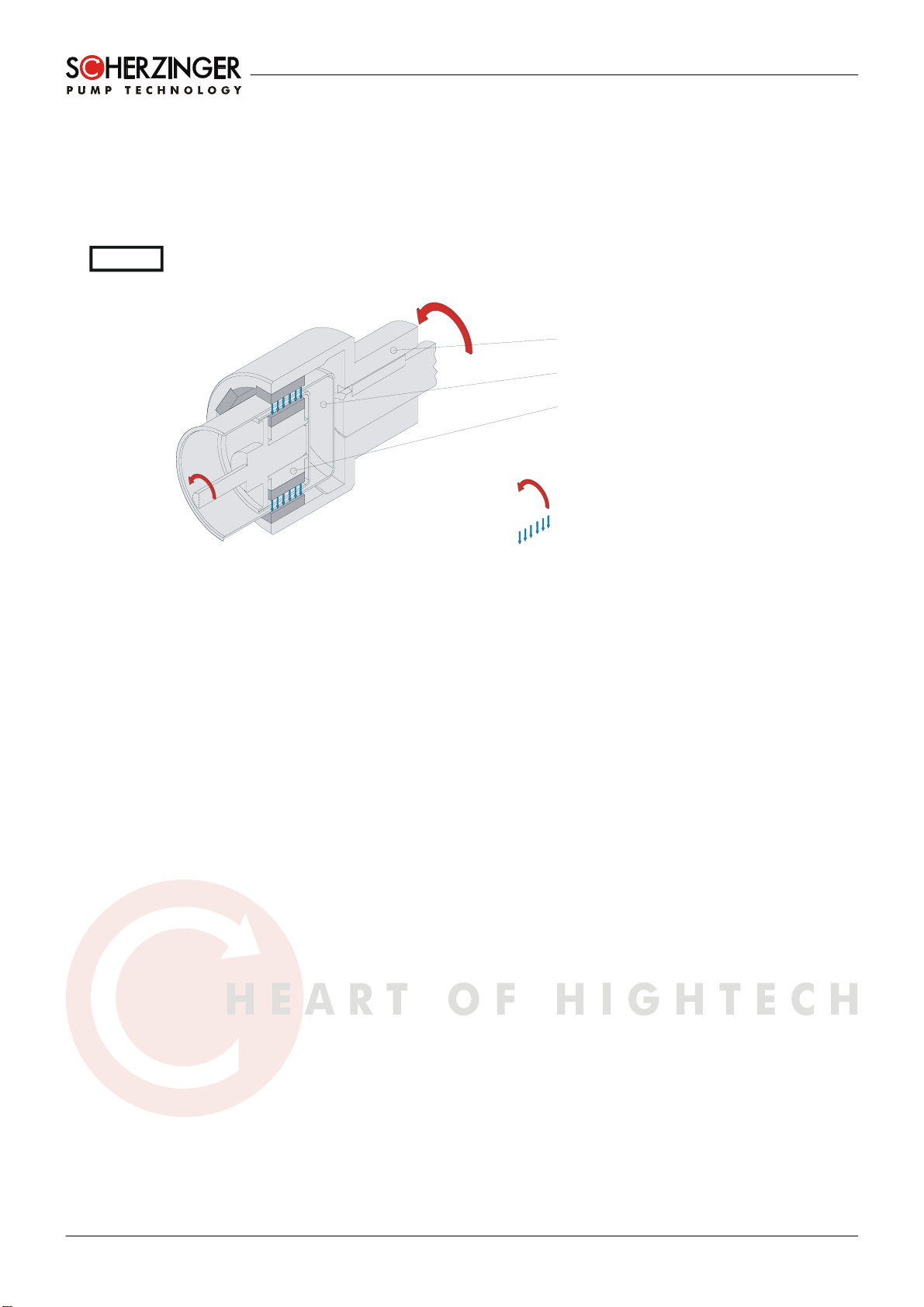
4.1. Principle of the gear pump
The pumping effect of a gear pump is created by the contra-rotation of two gears within a pump
housing. The gears are attached to two shafts, which, in turn, are supported on bearings in the
pump housing and cover. One of the two gears is driven by means of a shaft, the second gear is
driven by the gears meshing. The opening up of the tooth spaces creates a negative pressure
which sucks the liquid into the pump and transports it between the tooth spaces and the wall of the
pump housing. In the section where the gears engage with one another, the liquid is squeezed out
through the tooth spaces and into the outlet. Thus the liquid can also be pumped against a positive
pressure.
Picture 4.1 – Funktional principle of the gear pump
4.2. Design of the pump head
4.2.1. Basic principle
The pump head design, comprising three housing parts, casing [1], cylinder [3] and cover [2],
enables quick, easy and economical maintenance and servicing of the unit. The cylinder [3] and the
cover [2] are attached to the casing with four screws [21]. Two parallel pins [11] determine the
exact position. A sealing ring [10] is fitted between the casing and the cylinder, and between the
cylinder and the cover. The gears [6], [7] pressed onto the shafts [4], [5] are supported axially and
radially in the casing and cover. The shaft bearings in the casing and the cover are sleeve bearings
[8]. The rotary motion of the drive unit to the pump is transferred to the drive shaft with drive gear
by means of a magnetic coupling [18].
Scherzinger 8200 series laboratory pump heads are available with and without integrated pressure
relief valve and with different adapter motor adapters. For flow rates see chapter 1.3, pump data.
4.2.2. Pressure relief valve
The pressure relief valve (bypass valve) serves to limit pressure. The setting range is between 0
and 8 bars.
When the valve responds, the liquid reliefs back internally from the pressure side to the suction
side thereby preventing any damage within the system or to the pump head.
For adjusting the valve see section 6.3.
4.2.3. Magnetic coupling
The magnetic coupling gives the pump head a hermetic seal. In other words, the end of the rotating
shaft does not project out of the pump head. Leakage caused by wear and tear is eliminated as the
O-rings [10] only have to provide a static seal.
The required torque is transmitted through a non-magnetic partition wall (can [20]) to the hub of the
magnetic coupling [18] by means of six alternately magnetised magnets on the inner circumference
Description of the pump
10
Operating Instructions for Pump Type: 8200 ZK..., 8200 B/ ZK...
in the magnetic coupling cover. Six magnets are similarly arranged, alternately polarised on the
outer circumference.
The magnetic coupling also serves as an overload protection device for the pressure relief valve in
order to prevent damage to the pump head under higher pressures. As soon as the maximum
transferable torque is exceeded, the magnetic field is broken and the drive continues to run almost
without resistance; the system starts into a steady rattle and the pump head stops. Pumping
ceases.
Operating times exceeding 20 seconds in uncoupled mode result in the magnets heating up. The
magnets can become demagnetised: the required torque and therefore the achievable pressure
increase are reduced. Operation in this mode is to be avoided.
[24] & [25]
[20]
[18]
Direction of rotatio
n
Magnetic force
Picture 4.2 - Magnetic coupling
WARNING
Setting up / installation
Version: 5.1 11
5. Setting up / installation
5.1. Information about the operating location
Sufficient room for maintenance and servicing works must be ensured when selecting the operating
location. It should be possible to remove and re-install the pump without difficulty.
Do not install in aggressive atmospheres.
5.2. Electrical drive
The pump described in this operating instruction is supplied without a drive unit. The pump is
designed for assembly to an IEC Frame Size 71 motor with IMB14 or IMB15 adapter flange. Three
different adapter flange ODs are available: Ø 105mm, Ø 140mm or Ø 160mm. The requested OD
has to be determined when ordering the pump. Shaft must be Ø14x 30mm. The concentricity must
not exceed 0.1mm. Any other drive equipment matching similar specifications can be used.
Please do not exceed the maximum allowable speed range and the maximum allowable rated
speed based on the fluid viscosity (section 1.3).
Close attention should be paid to the explosion protection class of the pump and the explosion
protection class of all installed components. The nameplates on the individual components shall be
definitive in this regard. For use within hazardous areas, the lowest explosion protection class of all
the components used shall always apply.
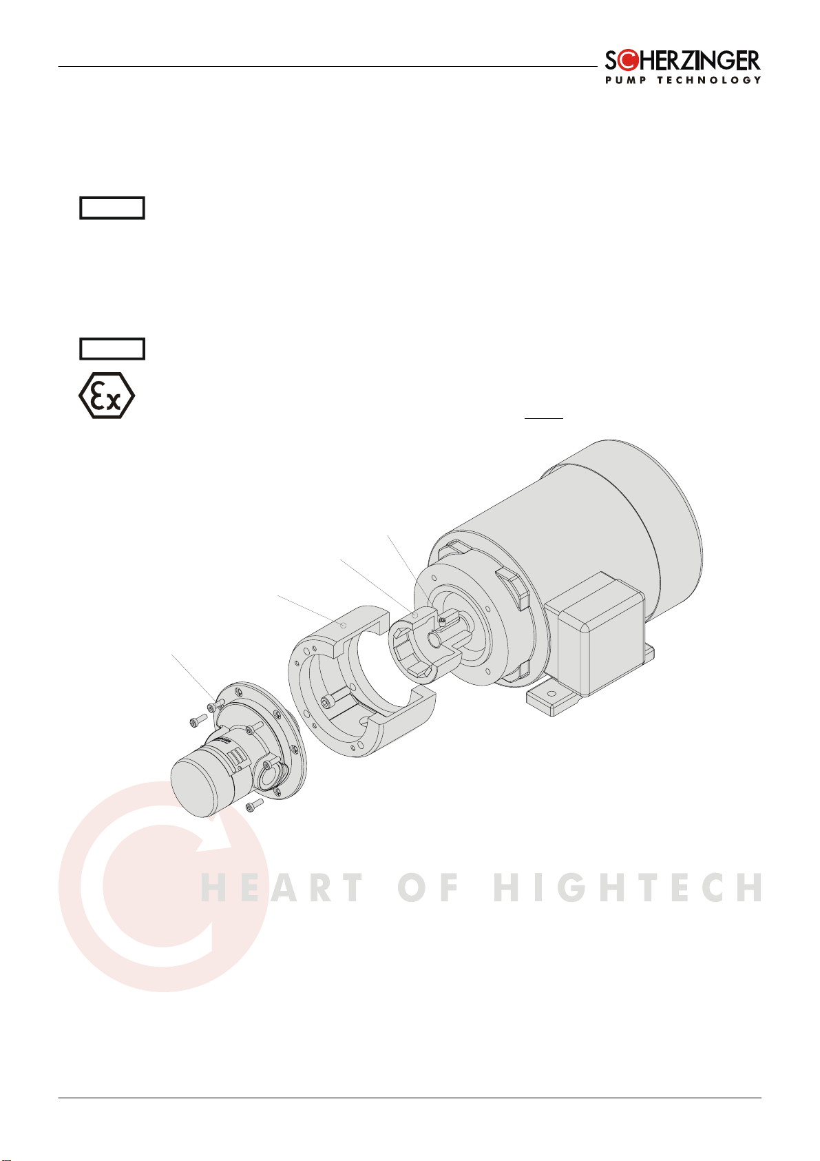
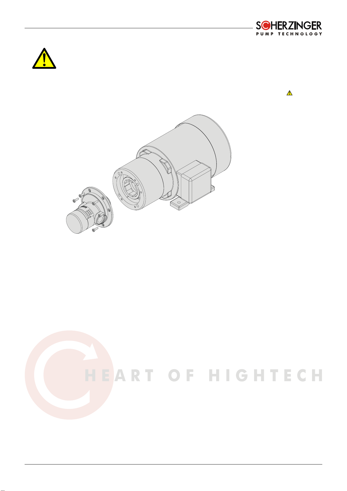
[24]
[27]
[22.2]
[26]
Picture 5.1 – Assembling the motor
When assembling the pump to the drive, do as follows (shown in Picture 5.1):
• Assemble the Magnetic Coupling [24] to the Drive Shaft. Make sure, that the bottom of the
coupling is even with the shaft end.
• Lock the coupling part by tightening the Locking Screw [26]. The magnets on the magnetic
coupling must not be dirty. Ensure that no metallic objects (swarf, screws, pins etc.) stick to
the Magnetic Coupling or the can [20].
• Disassemble the pump head from the adapter flange [27] by removing the 6 screws [22.2].
• Assemble the adapter flange to the drive. Use 4 hex head cap screws of the size M6x20
with adapter flange Ø105mm, M8x20 with adapter flange Ø140mm or adapter flange
Ø160mm
WARNING
WARNING

Setting up / installation
12
Operating Instructions for Pump Type: 8200 ZK..., 8200 B/ ZK...
• Assemble the pump head to the adapter flange. When brought near the drive, the pump
head is pulled towards the drive by the magnetic force. Ensure that there are no body parts
or objects between the pump and the drive (
risk of injury)
• Screw the Pump Head to the adapter flange by the use of the 6 screws (22.2)
During assembly to the motor, pay particular attention to the position of the Plug Screw [30]. This
must always face down in the final installation!
Ground the complete motor/pump unit. There is a grounding terminal in the terminal box of the
drive. As long as the drive is in metallic contact with the pump, this will suffice as grounding. When
mounting the motor, do not introduce any insulating elements between the pump adapter and the
motor. The threaded connection between the pump and motor must be made from
electroconductive material (e.g. steel).
The Magnetic Coupling must be ground by using the drive shaft.
Only carry out assembly work with the power supply switched off.
Never install a motor pump in a constricted installation location without sufficient ventilation as the
motor may be poorly cooled and could overheat.
The electrical connection of the motors must be implemented in accordance with the guidelines
issued by the VDE and/or the local power supply company. The operating manual supplied with the
motors must also be complied with.
To achieve the highest possible torque, particularly under heavy motor loads, three phase motors
should be connected in a delta circuit (check available main voltage).
5.3. First set up
You must check not only the type of protection class of the pump, but also the type of protection
class of all attached components. The name plates of the individual components are important. The
type of protection for the component with the lowest protection class always applies for the
operation in potentially explosive atmospheres.
Before starting, carry out a visual check for transport damage on the pump delivered by us (see
Section 3).
Then check on the basis of the following points whether the delivered pump type is suitable:
• Corrosion behaviour of the liquid
• Viscosity of the liquid
• Liquid to be pumped
• Pump performance (flow rate)
• Model type and design
• Direction of rotation and/or position of suction/pressure sides
• Temperature range
If you note any differences between the pump design you require in your system and the pump
delivered by us, please contact us immediately. Do not operate the pump before checking with us.
Screw the drive pump units only on to the mounts provided. The installation location must be level.
Level out any unevenness near the attachment points using suitable supports so that the four
support points are at the same level.
It is important that the set direction of rotation of the drive correctly relates to the desired pumping
direction. If the direction of rotation is changed then so will the direction of pumping. The pump
itself is designed to operate independently of the direction of rotation. This means that the pump is
not very likely to suffer damage. However, considerable damage to the system and danger to the
operating personnel could result if the pump is operated with the wrong direction of rotation.
A drop test in accordance with DIN EN 13463-1, Section 13.3.2.1 is not carried out. Protect the
pump as much as possible against shocks and impacts. In fact a shock or impact has an effect on
the pump's function but not on the explosion protection.
5.4. Connection Piping
Prior to connecting the suction and discharge pipes, check that the connection threads of the
pipework match those of the pump.
WARNING
WARNING
Setting up / installation
Version: 5.1 13
No stress or torque shall be exerted on the pump from the connection pipes and it may be
necessary to support the connection pipes directly in front of the pump ports. Similarly, no force
arising from thermal expansion shall be exerted on the pump.
The connection pipelines must be of adequate size. We recommend that they are not smaller than
the nominal size of the pump connections. On the suction side a nominal size bigger than the
nominal size of the suction connection of the pump is recommended. The approximate values for
the maximum flow velocities in the pipes are:
up to 200 mm²/s up to 600 mm²/s up to 2000 mm²/s
Suction pipe 1.5m/s 0.5m/s 0.2m/s
Pressure pipe 3.0m/s 1.0m/s 0.5m/s
Table 5.1 - Recommended flow velocities
To protect the pump from damage caused by solids in the liquid, we recommend a 50-micron filter
in the suction piping. Be sure the filter does not cause a serious pressure drop.
Suction piping should be as straight and direct as possible to the pump with a minimum number of
elbows. We recommend using long radius elbow type.
The suction pipe should have a continuous rise to the pump. If it is necessary to install rising and
descending pipe systems, there must be a provision to purge air at the highest points of the piping.
Once the pipes have been fitted, check that they are free from deposits, swarf or similar impurities,
as possible damage to the pump may result when the unit is put into operation.
Ensure that all pipes, fittings and screw joints are perfectly sealed. If this is not the case, gas may
enter the pump on the suction side. The pump may no longer provide adequate suction. The liquid
may escape on the pressure side. If a suction height of 3 m is reached, the installation of a check
valve in the suction pipe is recommended. The valve ensures that no liquid flows back through the
pump and that the suction pipe does not empty when the pump is switched off.
The pipe directly downstream of the pressure side should be laid with a rising gradient, at least for
a short distance.
Please note that with this installation situation, the inlet pressure is equal to the outlet pressure
when the pump is at a standstill. Please note the maximum system pressure on the pressure side
(refer to Section 1.3).
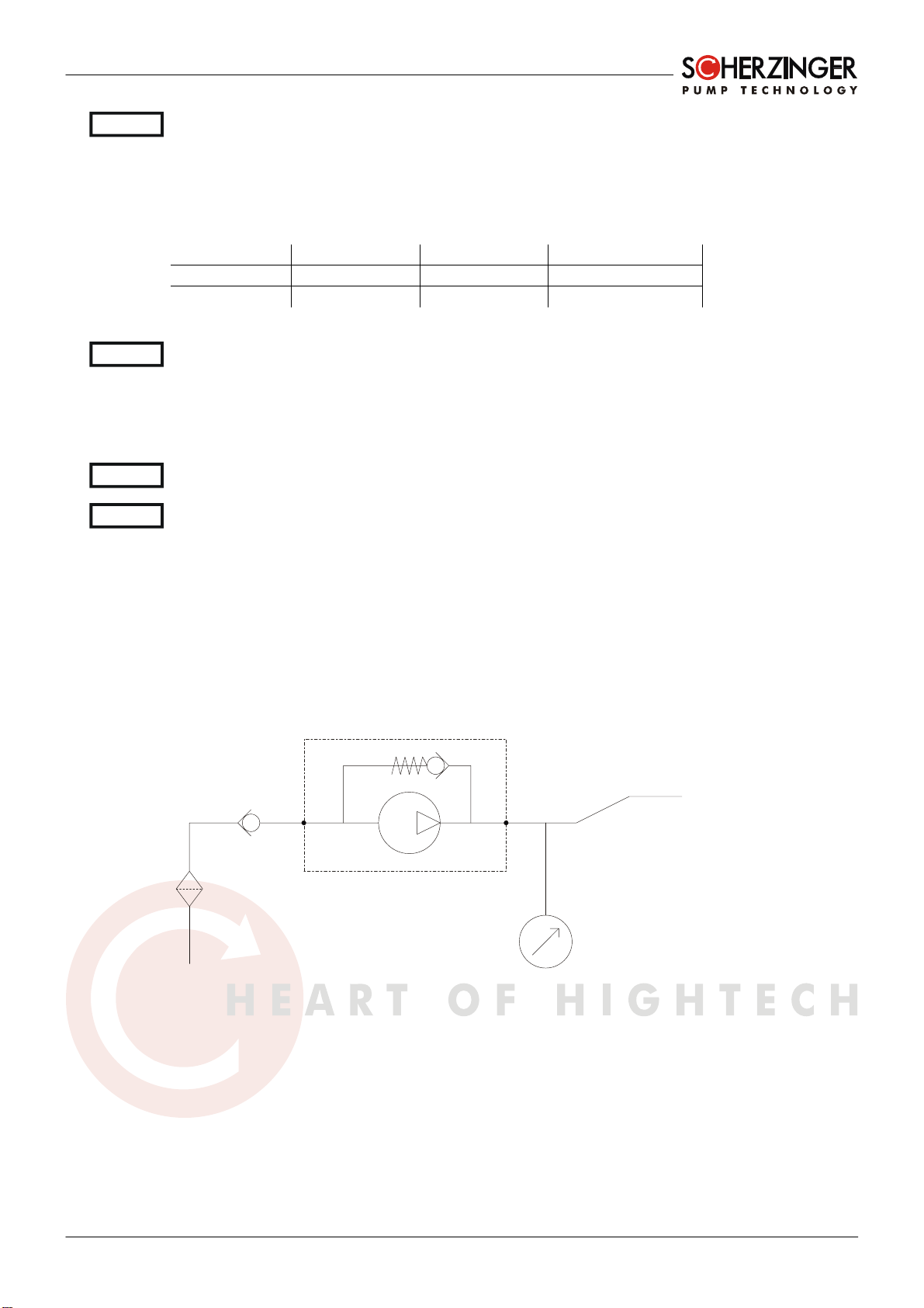
For installation in potentially explosive atmospheres the following installation is recommended:
pump
in out
check
valve
filter
temperature
gauge
rising
pipe
Picture 5.2 – Pipework installation
Noise insulation measures may be required on the pipework.
If the pump is not to be used in potentially explosive atmospheres, it may be helpful to install shut-
off valves upstream and downstream of the pump. This would allow the pump to be removed
without having to drain the pipe system.
WARNING
WARNING
WARNING
WARNING

Start up / shut down
14
Operating Instructions for Pump Type: 8200 ZK..., 8200 B/ ZK...
6. Start up / shut down
6.1. Preparation for operation
Following complete installation, check the pump and peripherals again by answering the following
list of questions:
• Can the pump be rotated by hand (e.g. when turning the motor fan)?
• Have you connected the suction and pressure sides correctly?
• Does the drive direction of rotation agree with that of the pump?
• Are the butterfly valves, gate valves and other valves in their correct positions?
• Has the pipe system been checked for leaks?
• Is it possible to stop the pump by an emergency switch in case of malfunction?
• Is there sufficient and the correct liquid in the tank?
• If the temperature difference between pump and liquid is greater than 50°C, the pump must
be tempered before starting!
Assembly work is only to be carried out with the drive unit switched off.
6.2. Starting operation
• Clean and disinfect the pump and pipe system if necessary.
• In order not to contaminate the liquid, it is recommended that a flushing process of at least 5
minutes is implemented with the liquid and at the appropriate pump speed to remove all test
liquid residues from the pump.
• Adjust the pressure relief valve in accordance to section 6.3
• Dry running time should not exceed 30 seconds.
The ignition temperature of the pumped liquid must be at least 50K above the maximum
permissible surface temperature.
6.3. Adjusting the Pressure Relief Valve (only B type)
Using the integral Pressure Relief Valve, it is possible to adjust a relative pressure rise to a specific
value.
Proper working order of the Pressure Relief Valve will be tested in the factory during the pump test
run. The pressure relief valve setting is only set at the factory when specifically requested in the
pump order.
The Pressure Relief Valve is adjusted while the pump is running. The pressure rise must be
measured between inlet and outlet side of the piping system. Ensure that the correct general
conditions (hereinafter operating conditions) exist when adjusting the valve:
• Pumped Liquid
• Temperature
• System Pressure
• Pump Speed
Picture 6.1 – Adjusting the relief valve

Start up / shut down
Version: 5.1 15
To adjust the Pressure Relief Valve proceed as follows:
• Loosen the Clamping Screw [13] by one quarter turn
• Adjust the valve by turning the Pressure Relief Valve Screw [12]
o To the left (counter-clockwise) ►reduces opening pressure
o To the right (clockwise) ►increases opening pressure
• Tighten the Clamping Screw [13] again
The pressure Relief Valve Screw [12] may only be unscrewed until it sits flush with the Clamping
Screw [13]. A loose Clamping Screw [13] may result in small quantities of leaked fluid escaping at
the pressure Relief Valve.
The pressure relief valve only serves as short-term overload protection. Longer opening times may
pose a danger of the pump head being damaged or ruined as a result of overheating. The surface
temperature may exceed critical levels (see Section 6.4).
The pressure relief valve is only a safety valve to protect the pump and the system. If you need a
exact adjustment of the output pressure use a precise pressure regulation valve. The integrated
pressure relief valve and as result the output pressure may oscillate.
6.4. Monitoring
The operator is exclusively responsible for the realization of the monitoring measures.
We recommend for pressure monitoring purposes, that a pressure monitoring device that meets
the operating requirements is installed on suction and pressure side. Stay within the parameters of
the pump data given in Section 1.3, otherwise the pump may become damaged.
If you operate a pump with internal relief valve against a closed system, the pump will heat up (see
figure 6.1 – surface temperature rise). Measurements show a surface temperature rise of 120 K
within 15 minutes (pump speed 2900 RPM, type B, relief pressure 7 bar, blocked pressure piping).
Under these operating conditions, the surface temperature must be monitored. Shut down the
pump at least 50 K below the max. allowed surface temperature, because the temperature can rise
delayed even after shut down.
0
20
40
60
80
100
120
140
0 2 4 6 8 101214161820
time (min)
surface temperature
rise (K)
figure 6.1 – surface temperature rise
The shut down temperatures with the definition according to T - classes are:
Temperature class T1* T2* T3* T4 T5 T6
maximum liquid
temperature 400°C 250°C 150°C 85°C 50°C 35°C
Table 6.1
* the pump is not intended for use with liquid temperatures above 130°C for PEEK gears and 70°C
for PTFE gears and such operation may cause irreparable damage to the pump.
WARNING

Start up / shut down
16
Operating Instructions for Pump Type: 8200 ZK..., 8200 B/ ZK...
For early detection of a leakage in the magnetic coupling area, you must:
• after use
• once a month
unscrew the plug screw [30] and check if leaked fluid has collected in the flange [27]. If it has, you
must switch the pump off immediately and eliminate the leak. ( Risk of injury: in the event of
leaks, hot, toxic or corrosive fluids may be discharged – wear suitable protective gloves). After
completing the check, put the plug screw back together with the seal. A pump without a plug screw
may not be used in II 2 D hazardous areas!
Remove dust from the pump surface, drive and connecting pipes regularly to avoid the formation of
a dust nest which could be an ignition source. The cleaning frequency is determined by the rate of
dust accumulation.
Monitor the noise level of the magnetic coupling. In the event of grinding sounds, turn the pump off
immediately. Inspect the pump for wear and tear. Metallic parts rubbing together can cause
overheating or sparking.
Dry-run protection does not have to be provided for the pump. Lengthy dry-run periods cause
irreparable damage to the pump but do not affect its use in Ex - areas.
If the pump is not fitted with an integrated overflow valve, we recommend using an external
overflow valve.
If you operate the magnetic coupling in uncoupled mode for long periods of time, the surface
temperature of the pump will rise. It may then exceed critical levels. The graph afterwards shows
the rise of the pump surface temperature when the pump is blocked.
0
2
4
6
8
10
12
14
16
0 102030405060708090100
time (min)
surface tempemperature
rise (K)
Chart 6.2 – surface temperature rise with blocked pump
6.5. Shut down
Make sure that there is no potentially explosive atmosphere.
• If possible, reduce the speed of the drive unit to 1500 RPM max.
• Empty the pump as much as possible by reducing the back pressure to 0 bar and opening
the suction pipe to atmosphere, so that the ambient air can be sucked in (
not if there is
system pressure, vacuum or reacting liquid).
• Ensure that dry-run times do not exceed 30 seconds.
• When liquids which could be hazardous to health have been pumped, rinse the pump head
out thoroughly with a suitable cleaning or neutralizing solution for several minutes.
• Finally, the pump head should be rinsed again with water.
If present, close the shut-off valves upstream and downstream of the pump. Close the shut-off
valves only, if the pump will stand still for a longer period of time (for automatic equipment, only
when the whole system is taken out of operation).
Start up / shut down
Version: 5.1 17
6.6. Removal from the system
Switch the drive unit off! Check that the steps described in Section 6.5 have already been
completed.
Remove the connection pipes.
Unscrew the six fixing screws on the flange [27]. The pump head is still held in place by the
magnetic force of the magnetic coupling. Pull it straight forward away from the motor. Risk of
injury!
Picture 6.3 – Removal from the motor

Servicing
18
Operating Instructions for Pump Type: 8200 ZK..., 8200 B/ ZK...
7. Servicing
7.1. General information
For servicing, it must be ensured that the pump has been rinsed out with safe liquid. If the pump
has been operated with hazardous fluids, servicing should be carried out with the appropriate
protective measures.
If the pump is being returned to the manufacturer for repairs or servicing, the clearance certificate
is to be completed fully and enclosed with the pump upon dispatch. Pumps sent for repair without a
clearance certificate will not be accepted.
7.2. Servicing
The pump is not subject to any routine service schedule. A service/clean is required when
• The pump is put into storage,
• The pump is switched off for an indefinite period,
• The pump no longer achieves the benchmark data indicated in Section 1.3
• Different fluids are being pumped,
• Leaks occur in the pump.
See also Section 3.3 and Section 6.4.
7.3. Disassembly and Reassembly
Particular care is to be taken to ensure that all O-rings are replaced upon reassembly as part of
any maintenance work that involves dismantling the pump head. Otherwise complete leakage
prevention cannot be guaranteed.
7.3.1. Assembly Equipment
The following are required for maintenance and assembly work:
• AF socket head screwdriver with handle 2mm, 2,5mm, 3mm, 5mm
• Flat-head screwdriver 12mm blade, 1.8mm blade thickness
• AF box wrench or engineer's wrench 21mm
• Internal puller for bearing bushes (inside diameter 7mm)
• Press-fit insertion die (external diameter 8,5 to 8,9mm)
• Torque screwdriver (50-500 Ncm)
WARNING

Servicing
Version: 5.1 19
7.3.2. Pump Bodies
Picture 7.1 – Pump body
Disassembly
• Remove the pump head from the drive unit (acc. section 6.6).
• Place the pump head in front of you with the stationary cup [20] facing upwards.
• Unscrew and remove the six hex head cap screws [22.3].
• Pull the stationary cup [20] upwards.
• Unscrew the grub screw [19] by one turn.
• Pull the magnetic coupling hub [18] upwards.
• Hold the pump head in front of you with the now free shaft end facing upwards.
• Unscrew and remove the four hex head cap screws [21.1] countersunk on the end face
• Pull the pump cover [2] carefully.
• Now the cylinder [3], parallel pins [11], drive shaft [4] with gear [6] and idler shaft [5] with
gear [7] can be removed.
Reassembly
• Hold the casing [1] flat side (smaller OD) up.
• Insert the drive shaft [4] (longer shaft) into the central pillow block of the casing [1] (longer
shaft end downwards).
• Insert the idler shaft [5] into the second sleeve bearing.
• Insert parallel pins [11].
• Attach the cylinder [3].
• Carefully place the cover [2] on the parallel pins [11].
• Turn the pump over. It is now lying with the free shaft end facing upwards in front of you.
• Screw in the hex head cap screws [21.1] and tighten with a torque of 220 Ncm.
• Put the magnetic coupling hub [18] onto the drive shaft [4].
• Tighten up the grub screw [19] with a torque of approx. 50 Ncm. Ensure here that the grub
screw reaches into the notch of the drive shaft [4].
• Put on the stationary cup [20].

Servicing
20
Operating Instructions for Pump Type: 8200 ZK..., 8200 B/ ZK...
• Screw in all six hex head cap screws [21.3] and then tighten on alternate sides with a torque
of 220 Ncm.
7.3.3. Pressure relief valve
Picture 7.2 – Pressure relief valve
Disassembly
• Dismantle the pump as described in Section 7.3.2.
• Pick up the cover [2].
• Unscrew the clamping screw [13] by one quarter turn with the engineer's wrench.
• Unscrew the pressure relief valve screw [12] until it is no longer engaged in the thread then
pull it out by hand.
• Unscrew the clamping screw [13].
• Remove all the other valve parts.
Reassembly
• Insert valve piston [15] with seal ring [17.2] and Valve spring [14] into the valve seat.
• Screw the clamping screw [13] in by hand.
• Screw in the pressure relief valve screw [12] until it sits flush with the clamping screw.
• Tighten the clamping screw [13] gently with the engineer's wrench.
• Proceed according to the reassembly instructions in Section 7.3.2.
7.3.4. Shaft bearings
Picture 7.3 – Shaft bearings
This manual suits for next models
1
Table of contents
Other Scherzinger Water Pump manuals

Popular Water Pump manuals by other brands

Nakayama
Nakayama NS2520 manual

ITT
ITT GOULDS PUMPS 3796 i-FRAME Installation, operation and maintenance manual

Tsurumi Pump
Tsurumi Pump HSD2.55S Operation manual

Schwing
Schwing SP 1800-D Original operating instructions

Pentair
Pentair MYERS MS50V10-R Installation and operation manual

VEVOR
VEVOR DC666-120V Operating instruction


VUOTOTECNICA
VUOTOTECNICA VTS 10 FG OPERATION AND MAINTENANCE BOOK

STOKES VACUUM
STOKES VACUUM 148-10 operating instructions

Sera
Sera PP 2500 INFORMATION FOR USE

ITT
ITT Goulds Pumps API 3171 Installation, operation and maintenance manual

Giant
Giant LP301A-5100 operating instructions

Crivit
Crivit 64305 instruction manual