page 4 of 6
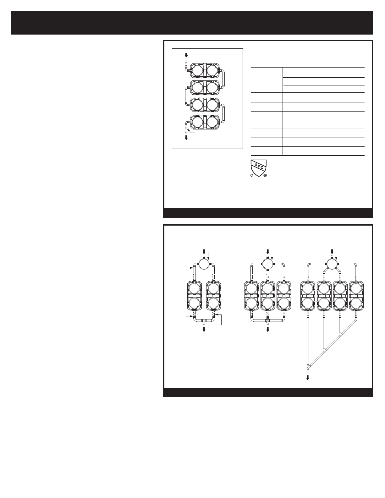
Table 1
Riser Height Needed Risers Required
0 - 3-1/2" None (use adapter)
5" - 23" SR24 (x2)
>23" - 38" LR24 (x2)
>38" - 43" SR24 (x4)
>43" - 58" SR24 (x2) + LR24 (x2)
>58" - 72" LR24 (x4)
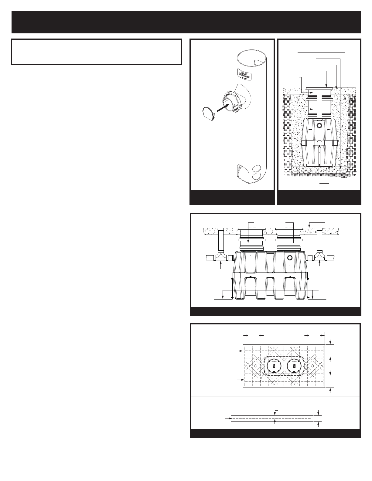
Riser
Height
Needed
Adapter
Riser
Cut Line
Alignment Mark
Figure 1 - Riser Measurements
6"
2"
4"
LR24
Long Riser
Adapter
SR24
Short Riser
Adapter (shown)
or Riser
Cover
Gasket
Upper Band Clamp
(
field adjustable)
Lower Band Clamp
(
factory set - do not
adjust or remove)
GB Unit (shown)
or Riser
Anchor hook
Anchor strap
Anchor plate
Figure 2 - Insertion Depths
ANCHOR KIT INSTALLATION DETAIL
2-1/2" Minimum Insertion Depth
4" Maximum Insertion Depth
(into GB unit only)
FIELD CUT RISER (24 SERIES)
INSTALLATION GUIDELINES
Tools needed: 7/16" Nut driver tool/bit (included), marker (included), tape
measure and drill with 1/2" chuck. Jigsaw, circular saw or reciprocating
saw will be needed if risers need to be cut.
NOTE: To remove a component or adjust its position, the Upper Band
Clamp needs to be loosened or removed using nut driver bit. The
Lower Band Clamp is factory set and should not be removed. For
proper fastening ensure clamps are tightened to 5 - 8 ft lbs. of torque
(same as a rubber no-hub coupling) prior to installation.
Riser Assembly Instructions/Steps
1. Set unit so the pipe connections line up with job site piping and
measure riser height needed from top of cover to finished grade.
See Table 1 to select risers needed.
2. Remove covers from adapters. Remove adapters from main unit.
On a level surface, pre-assemble the risers and adapters,
adjusting the components upwards or downwards to achieve the
riser height needed. Make sure to maintain minimum and
maximum insertion depths as shown in Figure 2. If components
are too long, make a circular line around the sidewall with marker
and cut with a power saw. The lowest cut line on the riser assembly
will be 6" beyond the riser height needed to allow for ideal insertion
depth (See Figure 1). An alignment mark should be drawn 2"
beyond the riser height needed which will align with the top of the
base unit gasket. DO NOT cut the alignment mark. The Adapters
and risers should sit level with each other. Tighten upper clamps
to keep riser/adapter assembly from shifting. Make alignment
marks on the sidewalls at the top of all riser gaskets to aid final
assembly.
3. IMPORTANT: Before the next step, make sure both diffusers are
installed inside the main unit at the appropriate locations. Check if
there needs to be any flow control adjustment at the inlet diffuser
(see general installation instructions).
4. Take apart riser assembly and clean all sidewalls and insides of
gaskets to remove dust/debris. Install components into the main
units starting from the lowest riser and work your way up to finished
grade. Ensure that riser will not interfere with diffuser, allow min. 1"
clearance. Maintain minimum and maximum insertion depths for all
components (see Figure 2). Tighten Upper Clamps to specified
torque after correctly positioning components. Riser assembly may
need to be supported during backfill.
5. If tilting of the adapter is required to be flush with grade, do so
AFTER all clamps have been tightened with riser(s)/adapter in a
vertical and level position. Tilting is done using gasket flexibility.
Tilting before tightening clamps may ruin a perfect gasket seal.
Schier recommends tilting only the adapter versus the entire
riser assembly to make sure your riser height and proper tank
access is maintained.
6. If riser height conditions change after completing above steps,
there may be room for adjustment. As long as minimum and
maximum insertion depths are maintained (see Figure 2), the
adapters/risers can be adjusted/cut as many times as neces-
sary.When riser system installation is complete, see Leak/Seal
Testing procedure if required (pg 3 of 6).
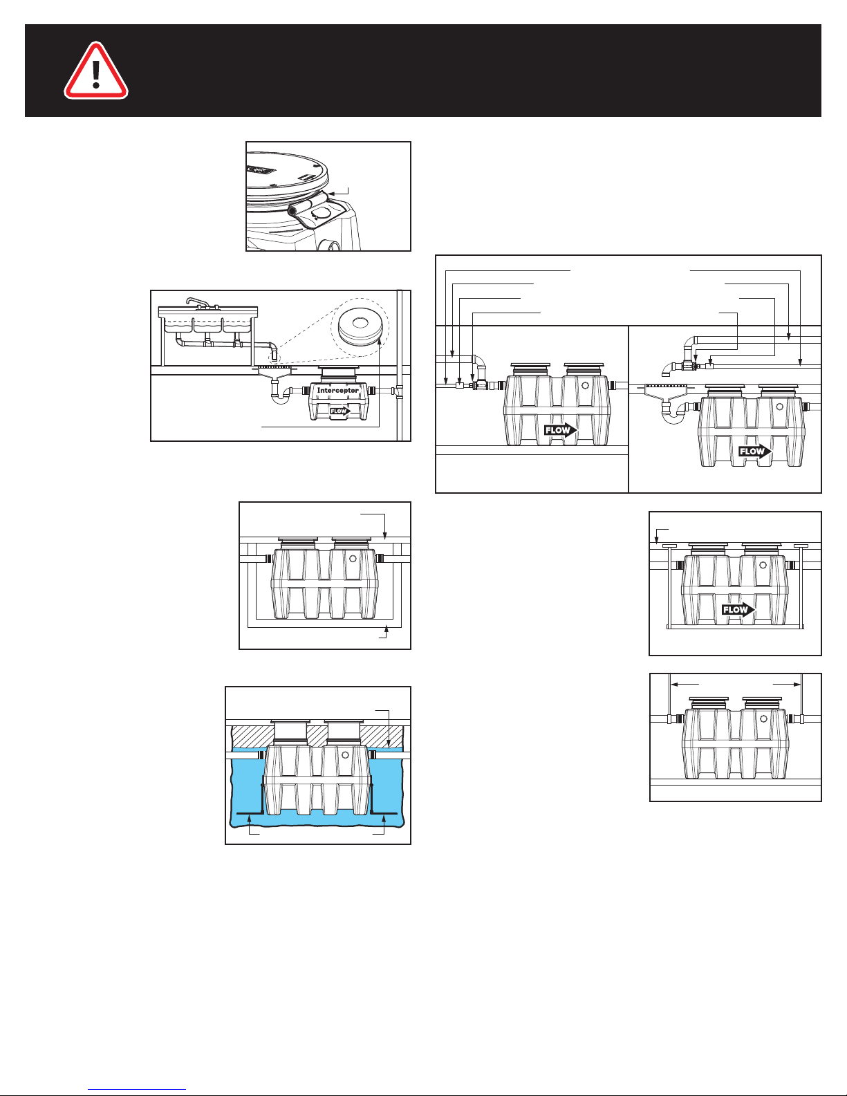
ANCHOR KIT INSTALLATION
Stainless steel anchor kit is recommended for installation in high
water table conditions to prevent float out. Necessity to be deter-
mined by specifying engineer. Hold down force achieved by backfill
weight acting on Anchor Plate.
Slide Anchor Hook over tie down point on end wall and bolt to Anchor
Strap. Bolt Anchor Strap to Anchor Plate using provided stainless
steel hardware. If required, Anchor Plate may be bolted to concrete
slab using provided holes.
Field Cut Riser
Components
057-0780-05
INSTALLATION (2 of 3)