Schill FT 038 Series User manual

automatic cable rewinder FT 038 e-mobility with integrated charging electronic
installation and operating instruction
installation and operation instruction FT 038 e-mobility miL - A4 - version B Seite 2 11.03.2021
Schill GmbH & Co. KG; Bruckstraße 44; 70734 Fellbach www.schill.de
INTRODUCTION
All information necessary for a correct assembly to ensure trouble free operation of the
cable reel are described in the present operating instructions. The warranty given by the
manufacturer is only valid if these operating instructions are observed and adhered to.
Terms and conditions are available upon request or at https://www.schill.de/AGB_en
Additional user manuals for other product variants can be found at
https://www.schill.de/en/downloads/ or received on request (see "CONTACT").
GENERAL
The automatic cable rewinder with integrated charging electronics provides the simple
means for modern AC charging of electrically powered vehicles (EV). The cable is only
pulled out when needed and in the required length. The remainder stays neatly stored on
the cable reel and is protected from contamination and damage. The power connection is
always accessible, but never in the way. The cable length can be easily adapted to a
changing parking situation. There is no cable chaos, no tripping hazard anymore. If the
charging connection is no longer needed, a short pull on the cable stopper will suffice and
the cable will roll up neatly. The automatic cable rewinder ensures safety and order.
HANDLING
The coiled cable should be pulled out to the required length against the spring tension, but
please refrain from the use of undue force. The cable is coiled and fixed in position as
described under "LOCKING DEVICE". The cable should never be pushed in manually. If
the cable becomes entangled when winding it onto the reel, simply pull the cable out again
and then rewind.
Incorrect use caused by torsional stress together with simultaneous expansion of cable
should be avoided.
MAINTENANCE
The cable reel does not require any maintenance, due to the excellent antifriction
properties of the plastic bearing. However, the cable must be checked in regular intervals
for damages and replaced if necessary.
SPIRAL SPRING
The spiral spring is subject to natural wear and tear causing a fatigue fracture of the spring
steel. Based on experience, we recommend changing the spring after approx. 30.000
operations. The term “operations” defines not only a complete winding and unwinding of the
spring but includes also a partial movement of the spring.
In the event of spring breakage or spring fatigue, please contact us (see "CONTACT").

automatic cable rewinder FT 038 e-mobility with integrated charging electronic
installation and operating instruction
installation and operation instruction FT 038 e-mobility miL - A4 - version B Seite 3 11.03.2021
Schill GmbH & Co. KG; Bruckstraße 44; 70734 Fellbach www.schill.de
SPRING LOAD
The spring load is set at the factory. It may become necessary to adjust this setting. Before
doing so, the locking device should be engaged. Then remove the cable stopper and draw
the cable out of the roller guide. The load can be increased by additional windings of the
cable anti clockwise and decreased by unwinding the cable in clockwise direction (rewind).
Once this has been completed, it is very important that the cable is fed back through the
roller guide and secured with the cable stopper. Increasing the spring load reduces the
extractable cable length. A reduction of the spring load may affect the rewind function of
the reel.
ATTENTION
Do not release the cable when rewinding, the tension of the spring can accelerate
the winding speed to such a degree that the swinging cable end could cause injury.
Also damage to the cable and spring could be the result of such an action.
CABLE STOPPER
The length of the available cable can
be individually adjusted with the
provided cable stopper. The reliable
clamping adapts to various cable
diameters between 6 and 16 mm. For
a thicker cable, a larger version is
available. The stopper also serves as
a safeguard against a full unload of the
spring if the cable is unintentional
released. It should therefore never be
removed.
ROLLER GUIDE
Fitted with four rollers, the roller guide ensures that
the cable is correctly guided. It can be operated in a
fixed or flexible mode. The roller guide adjusts then to
the direction of the pull. The guide ensures that the
cable is always guided onto the reel and prevents it
from sliding of the drum.

automatic cable rewinder FT 038 e-mobility with integrated charging electronic
installation and operating instruction
installation and operation instruction FT 038 e-mobility miL - A4 - version B Seite 4 11.03.2021
Schill GmbH & Co. KG; Bruckstraße 44; 70734 Fellbach www.schill.de
LOCKING DEVICE
As a standard feature the cable reel has a
disengageable cable locking device. The
latching mechanism ensures that the pulled-out
cable stays without traction fixed in place.
When the cable is being pulled out, the spring
detent passes over a series of grooves. An
audible click indicates that the locking device is
engaged. If you gently rewind the cable after
the clicking sound, you will notice that the
spring detent will engage into the notches,
locking the cable in position. The cable can be
disengaged by gently continuing to pull the
cable until the click can no longer be heard.
The loaded spring will pull the cable back onto the reel.
The locking device can be disengaged by pulling the knurled grip out by approx. 1cm and
turning it between 90°and180°. This will disengage the locking device the cable is then
constantly under tension.
ATTENTION
Do not release the cable when rewinding, the tension of the spring can accelerate
the winding speed to such a degree that the swinging cable end could cause injury.
Also damage to the cable and spring could be the result of such an action.
CONNECTING
To connect the reel to the mains/supply service a connection cable is mounted. As a
standard a plug-in connector is not included in the scope of supply.
Depending on the version, the reel can be delivered with
oa connection cable only (standard)
owith an on the reel mounted terminal block

automatic cable rewinder FT 038 e-mobility with integrated charging electronic
installation and operating instruction
installation and operation instruction FT 038 e-mobility miL - A4 - version B Seite 5 11.03.2021
Schill GmbH & Co. KG; Bruckstraße 44; 70734 Fellbach www.schill.de
ATTENTION
•Observe installation instructions
•According to DIN VDE 0100-722 (VDE 0100-722): 2013-01, a separate circuit must
be set up for each charging socket (IEC 60364-7-722: Low-voltage electrical
installations - Part 7-722: Requirements for special installations or locations -
supply of electric vehicle)
•Protection via residual current device (RCD) at least type A, which switches off
with AC or pulsating residual current with IΔn ≥ 30mA
•If DC fault currents IΔn ≥ DC 6mA can occur due to insulation faults in the
charging circuit, a residual current device (RCD) type B is required or suitable
protective measures for DC fault currents ≥ DC 6mA must be provided (e.g. DC
residual current monitoring device).
EXTENSION CABLE
The included standard cables are designed to tolerate the weight of the pulled-out cable
including the cable stopper. Additional weights are not allowed. The mounted cables are
limited to the specified lengths. Never use excessive force to unwind the cable as this can
damage both the cable and the reel. Should the cable be blocked while coiling up, please
pull the cable out again and recoil. Attention should also be paid to section „GENERAL".
If the cable is damaged, please contact us (see "CONTACT").
FUSE / THERMAL SAFETY GUARD
The integrated charging electronics is protected with a 5x20 glass bulb fuse. Accessible
from the outside, this is located on the operating and signaling devices on the front of the
charger. To change the fuse, remove the cap of the fuse holder the glass bulb fuse can
then be replaced.
The series of these automatic cable reels with integrated charging electronics is
dimensioned in such a way that no excessive heat is generated when the cable is reeled
or unreeled. For protection in case of unusual heat development, a self-holding or self-
switching temperature switch is installed, depending on the version. In the event of
tripping, the charging of the electrically powered vehicle is interrupted. After a cooling
phase, the temperature switch switches itself on or is reactivated by pressing the red
temperature switch. Charging operation is resumed (see also "OPERATING AND
MESSAGE ELEMENTS").
READY FOR USE
Before commissioning, please conduct an electrical check according to VDE 0100 or to the
respective national standard. Check that the end of the pull-out cable is correctly fitted with
a charging socket. After connecting to the power supply (see "CONNECTING"), the cable
reel should be live and ready for use.
If this is not the case, the fuse and thermal safety guard must be checked (see "FUSE /
THERMAL SAFETY GUARD").

automatic cable rewinder FT 038 e-mobility with integrated charging electronic
installation and operating instruction
installation and operation instruction FT 038 e-mobility miL - A4 - version B Seite 6 11.03.2021
Schill GmbH & Co. KG; Bruckstraße 44; 70734 Fellbach www.schill.de
INSTALLATION
Pull out the extension cable to the desired length and lock. Connect the charging socket to
the electrical vehicle (EV). Switch on the automatic cable reel with integrated charging
electronics using the rocker switch (ON / OFF). A flashing LED (STATUS CONTROL)
signals operational readiness. If this is not the case, the fuses must be checked. Observe
the description under “OPERATING AND SIGNALING ELEMENTS”.
If the charging electronics are equipped with an AC / DC sensitive residual current
monitoring device, this must be checked for proper function before each charging process.
It is necessary that the charging process is deactivated (no vehicle connected). Observe
the notes under "OPERATING AND SIGNALING ELEMENTS"
ATTENTION
Danger to life from electric current!
Safety for life is only guaranteed if the monitoring device functions properly.
Therefore, a device test (by the charge controller) must be carried out before each
charging process!
OPERATING AND SIGNALING ELEMENTS
FT 038.0516.I02 / FT 038.1032.I02

automatic cable rewinder FT 038 e-mobility with integrated charging electronic
installation and operating instruction
installation and operation instruction FT 038 e-mobility miL - A4 - version B Seite 7 11.03.2021
Schill GmbH & Co. KG; Bruckstraße 44; 70734 Fellbach www.schill.de
FT 038.0516.I03 / FT 038.1032.I03
Switch ON / OFF:
Switches the integrated charging electronics on or off. The charging electronics must be
switched off after each charging process.
Signal lamp STATUS CONTROL (LED yellow)
Different flashing frequencies of the indicator light is shown the status of the charging
controller.
flashing
frequency
meaning
1x fast + pause
No vehicle detected - standby
2x fast + pause
Vehicle detected
1x long + pause
Vehicle requests charging (contactor is ON)
20x fast in 0,5 sec
The current setting mode is called up or exited
1x each 0,3 sec
Current setting mode –one more amper set
error states (no charging)
3x fast + pause
controller is disabled in software (FW >= 6)
4x fast + pause
charging with ventilation is disabled (FW >= 13)
5x fast + pause
Pilot signal check failed (FW >= 11)
6x fast + pause
Residual current check failure (FW >= 16)
Signal lamp LOAD ACTIVE (lamp green):
Contactor is switched (loading vehicle)

automatic cable rewinder FT 038 e-mobility with integrated charging electronic
installation and operating instruction
installation and operation instruction FT 038 e-mobility miL - A4 - version B Seite 8 11.03.2021
Schill GmbH & Co. KG; Bruckstraße 44; 70734 Fellbach www.schill.de
FUSE:
Protection of the charging electronics
Signal lamp STATUS DEVICE (lamp green):
AC / DC sensitive residual current device: no device fault
Pushbutton TEST / RESET:
The device test for residual current monitoring is carried out with the push button.
The device test is carried out via a connected measuring current transformer. The effective
value of the direct current component contained in the differential current and the
alternating current component below the cut-off frequency is formed. The alarm relays
switch when the limit values of IΔn≥ DC 6 mA and / or effective value IΔn≥ 30 mA are
exceeded. The regular check increases the safety of the charging process and prevents
long-term drifting of the residual current measurement.
Fault storage is integrated in the residual current monitoring. An error that has occurred or
a test that has been carried out must be reset manually using the pushbutton. (The error
storage can optionally be switched off, then the reset takes place automatically as soon as
the residual current fulfills the connection condition.
THERMAL SWITCH:
Switches off the charging process when a critical temperature is reached
If the electronics of the automatic cable winder are defective, please contact us (see
"CONTACT").
TECHNICAL DATA
The cable reels consist of a plastic drum core with coated steel discs and a steel bracket.
Is corrosion resistant and has very good winding and running characteristics due to the
ball-bearing axle. The stable construction is designed for operation in factories and
workshops. The cable reels are supplied as standard without a plug device.
•Spiral spring for approx. 30. 000 operations
•Disengageable cable locking device
•High quality flat slip rings 240 / 400V AC - 16A with double contacts
•flexible and lockable cable guide
•Mounting fixture WB 038 for wall installation (standard)
•Mounting fixture DB 038 for ceiling installation (optional)
•Ambient temperature range: -20°C bis 40°C
•IP classification: IP 42
•Construction: protection class I
•Protection / internals
➢Temperatur protection device:
▪self-retaining Thermal switch (56°C±5°C)
▪self-retaining Thermal switch (O65°C±5°C / C50°C)
➢Glass bulb fuse 5x20 400mA slow
➢Installation contactor 4way 40A

automatic cable rewinder FT 038 e-mobility with integrated charging electronic
installation and operating instruction
installation and operation instruction FT 038 e-mobility miL - A4 - version B Seite 9 11.03.2021
Schill GmbH & Co. KG; Bruckstraße 44; 70734 Fellbach www.schill.de
•Input / power connection
➢Connecting cable (standard 2m / optional >2m)
▪H07RN-F 3G2,5 (3,7kW) / H07RN-F 3G6 (7,4kW)
▪H07RN-F 5G2,5 (11kW) / H07RN-F 5G6 (22kW)
➢Nominal Voltage 230V / 400V AC
➢Rated Current: 16A / 32A
➢Nominal frequency: 50Hz
➢16A / 32A back-up fuse (optional or required by customer) recommended C-
characteristic
➢RCCB type A, 30mA (optional or required on site)
➢DC residual current detection electronic, IΔn DC ≥ 6mA (optional or required on
site)
➢as an alternative to DC residual current detection and RCCB type A. RCCB RCCB,
type B (optional or required on site)
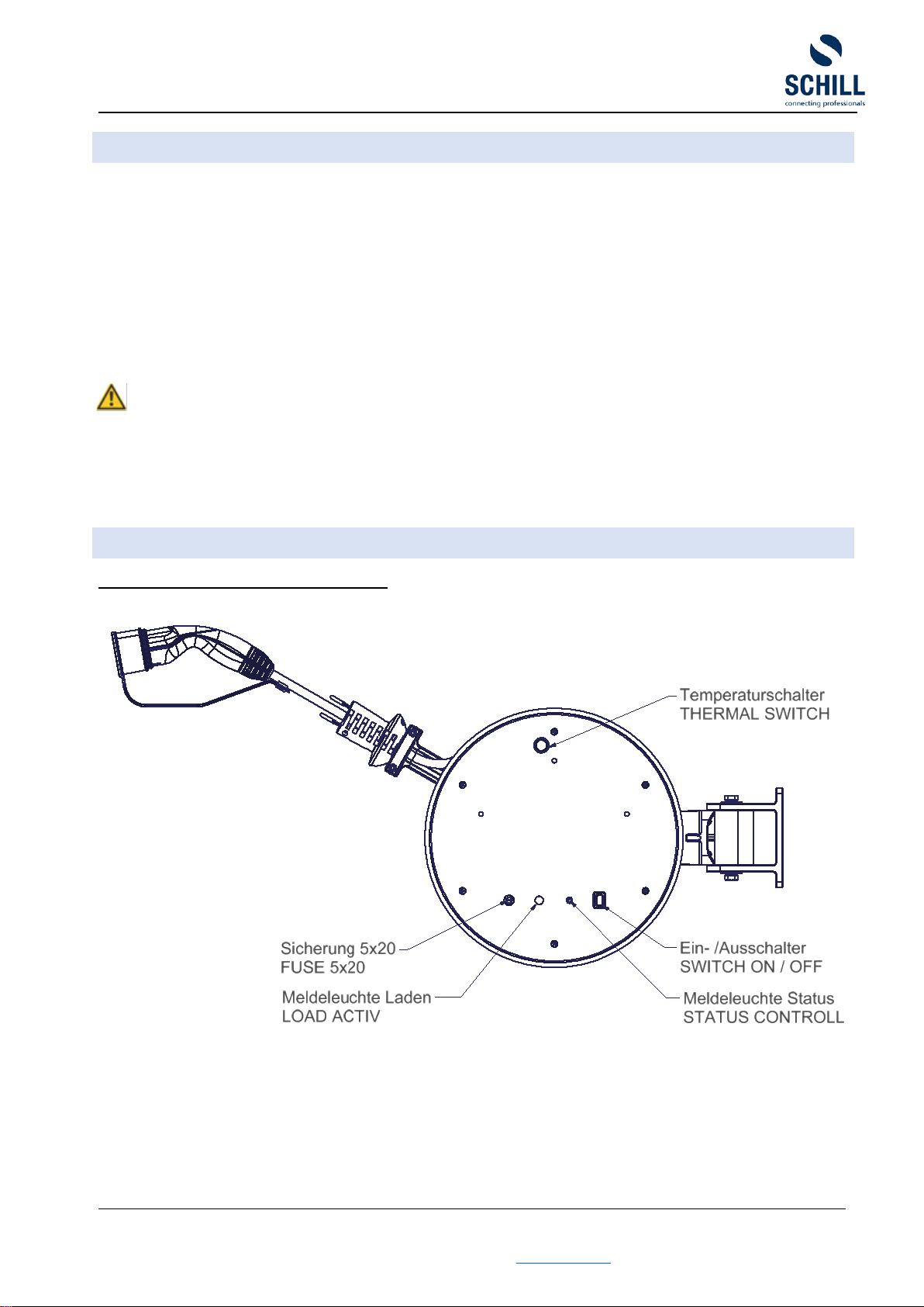
•Output / vehicle connection
➢Max. 10m extension cable with connector Typ 2 (optional Typ 1)
▪5G2,5 + 1x0,5 (11kW) 3G2,5 + 1x0,5 (3,6kW)
▪5G6 + 1x0,5 (22kW) 3G6 + 1x0,5 (7,2kW)
Standards for the charging cable: IEC 60332-1; IEC 60228; DIN EN 50620; DIN
EN 50363-10-2; DIN EN 50267-2-1; DIN EN 50363-10-2; ISO 4982-2
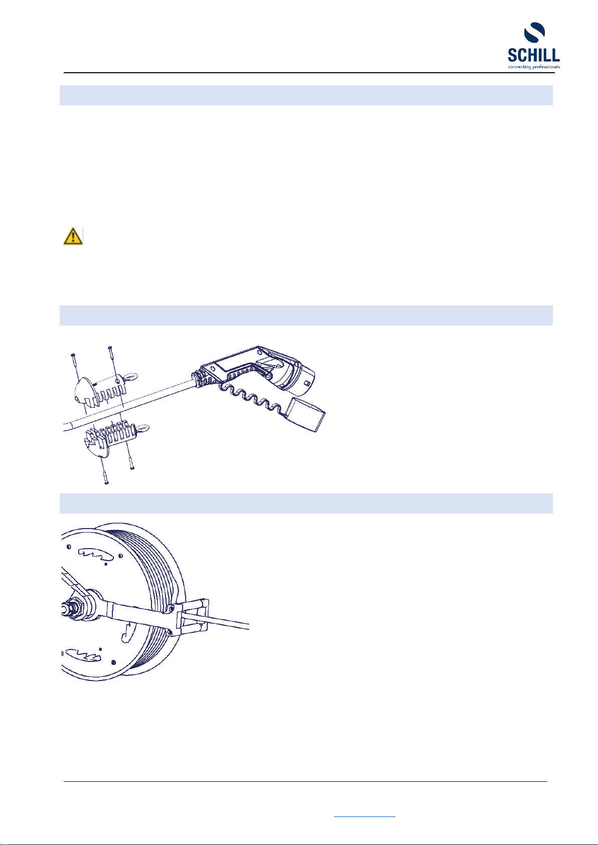
➢Cable stopper with segmented gentle clamp 6 –16 mm
➢Output Voltage: 230V / 400V AC
➢Maximum charging current [A]: 16 / 32
➢Maximum charging power [kW]: 3,6 / 7,4 (1ph) - 11 / 22 (3ph)
➢Communication EV according to IEC 61851-1, mode 3
The stated operating temperatures relate only to the standard cable reel as described
above and do not apply to e.g. plug-in device. They are only as an exception part of the
delivery. Specification for plug-in devices can be found within the relevant standard DIN
EN 60309 or respectively DIN VDE 0620. For other operating temperatures please
contact us.
Additional information with respect to cable types, spring tensions, power loads and
weights can be found on the product rating plate, in our current product catalogue and also
on our website www.schill.de/en
The dimensions, weights, lengths, coloures and traction are subject to modifications. We
cannot rule out discrepancies and we reserve the right to make technical changes to the
product without giving advance notice.
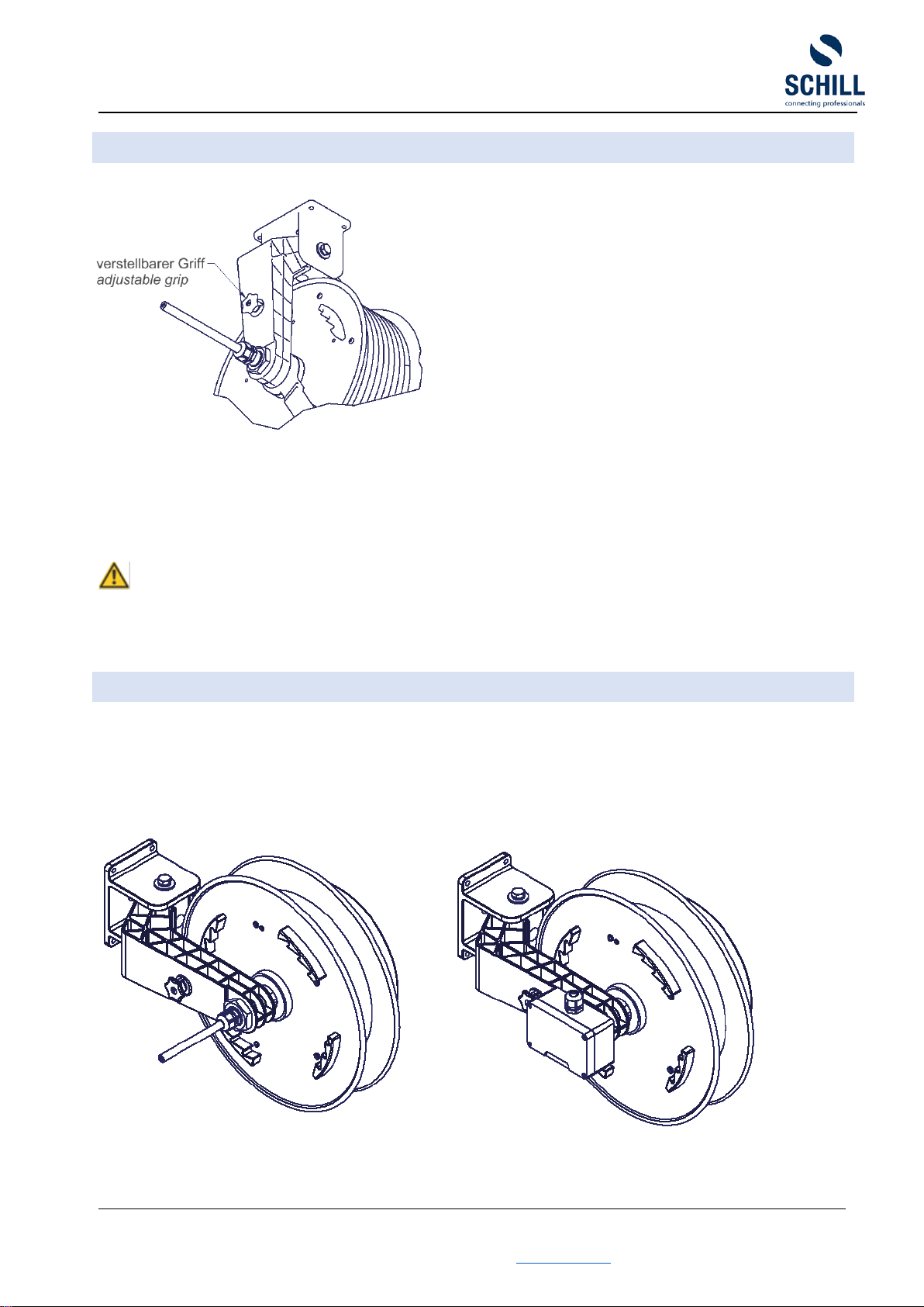
INSTALLATION HEIGHT
The installation height of the cable rewinder is not limited. The maximum extension length
is the specified cable length. The standard cables are designed to withstand the weight of
the extended cable included cable stopper. Additional tensile forces (cause by additional
weights for example) are not permitted.
When the cable is pull-out horizontally due to the weight of cable a slack occurs. This is
about 10% of the cable pull-out length.

automatic cable rewinder FT 038 e-mobility with integrated charging electronic
installation and operating instruction
installation and operation instruction FT 038 e-mobility miL - A4 - version B Seite 10 11.03.2021
Schill GmbH & Co. KG; Bruckstraße 44; 70734 Fellbach www.schill.de
FITTING INSTRUCTION
Wall installation with universal holder WB038
The cable reel can be rotated 150°.
Depending on the mounting height, the rotatable roller guide can be adjusted to the cable
pull direction and fixed.
Mounting fixture WB 038 for wall installation Ceiling installation rotating DB 038
Mounting fixture WB 038 is included in
the scope of
supply, but no fastening
screws.
Mounting fixture DB 038 and fastening
screws are not in the scope of
supply
Ceiling and floor month with DB038

automatic cable rewinder FT 038 e-mobility with integrated charging electronic
installation and operating instruction
installation and operation instruction FT 038 e-mobility miL - A4 - version B Seite 11 11.03.2021
Schill GmbH & Co. KG; Bruckstraße 44; 70734 Fellbach www.schill.de
The extension cable swivels on a 360° axis. The
swivel roller guide is to be adjusted to the cable
extension direction and secured (screw
connection) in this position.
ATTENTION
If repeated over-tightening, the connection
cable can be mechanically stressed and torn
off.
TIGHTENING TORQUE
Gehäuseschrauben
Cover screws
0,8 Nm
Sicherungsschraube. M8
Locking screw M8
0,8 Nm
Zugentlastung
Strain relief
0,8 Nm
Kabelstopper
Cable stopper
0,8 Nm
Schraubenmutter M30
Screw nut M30
40 Nm
Kabelverschraubung
Cable gland
2,5Nm
Elektrische Anschlüsse
Electrical connections
0,5 Nm
MS-Schleifring Mutter M3,5
MS slip ring nut M3,5
0,3 - 0,35 Nm
MS-Schleifring Schraube M3
MS slip ring screw M3
0,6 - 0,7 Nm
Doppelschenkelhalter M5/M6/M8
Double brush holder M5/M6/M8
2,8 / 4,8 / 10 Nm
Schleifringkörper M5/M6/M8
Slip ring body M5/M6/M8
2,8 / 4,8 / 10 Nm

automatic cable rewinder FT 038 e-mobility with integrated charging electronic
installation and operating instruction
installation and operation instruction FT 038 e-mobility miL - A4 - version B Seite 12 11.03.2021
Schill GmbH & Co. KG; Bruckstraße 44; 70734 Fellbach www.schill.de
DIMENSION FT 038.05XX.IXX.

automatic cable rewinder FT 038 e-mobility with integrated charging electronic
installation and operating instruction
installation and operation instruction FT 038 e-mobility miL - A4 - version B Seite 13 11.03.2021
Schill GmbH & Co. KG; Bruckstraße 44; 70734 Fellbach www.schill.de
DECLARATION OF CONFORMITY
Declarations of conformity are available at https://www.schill.de/en/downloads/ or upon
request (see “ CONTACT”)
SPARE PART ORDER
If you require spare parts, please contact our local distribution partner or give us a
product number or the part number ready.
CONTACT
Administration Fellbach
Schill GmbH & Co. KG
Bruck Straße 44
70734 Fellbach
Telefon: +49 (0)711 578807-0
Telefax: +49 (0)711 578807-44
E-Mail: [email protected]
Manufacture Laichingen
Schill GmbH & Co. KG
Hirschstr. 81
89150 Laichingen
Telefon: +49 (0)7333 9648-0
Telefax: +49 (0)7333 9648-44
E-Mail: [email protected]
CHANGES
version
changes
date
A
extended display indicator signal lamp status control / update
25.09.2020
B
temperature switch (Ämt. 2021_02) / update
11.03.2021
This manual suits for next models
5
Table of contents
Popular Automobile Accessories manuals by other brands

Kuda-Phonebase
Kuda-Phonebase 296010 Installation instruction

Dynojet
Dynojet Power commander V installation instructions

iDataLink
iDataLink maestro SW quick start guide

Whispbar
Whispbar K549W Fitting instructions

Hella
Hella Headlamp Cleaning System installation instructions

Camos
Camos RV-752 instruction manual