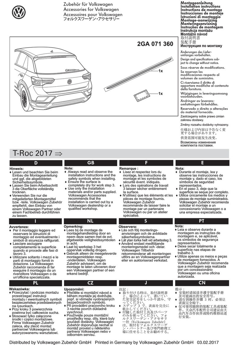
Steel mate PTS411M23 User manual

PTS411M23
Manual
Dual-Purpose Parking Assist System
(Front or Rear)

01
User Manual
The PTS is designed as a driver assistance
device, and should not be used as a substitute for
safe parking practices. The area into which the
vehicle is to be reversed must be constantly
monitored while parking.
The manufacturer and its distributors do not
guarantee or assume liability for collisions or
damages while reversing and braking the vehicle.
Parking Assist System (PTS) helps to provide
assistance when reversing and parking. Driving
skills such as slowing down, use of mirrors are
always essential.
This system is for vehicles with DC 9~27V
only.
This system should be installed by a
professional auto technician.
Route wiring harness away from heat source
and electrical components.
It is strongly recommended to check the
position of the sensors before the actual
drilling of the holes.
Perform a functional test after installation.
Important notice
Disclaimer
Contents
01
01
02
02
02
03
03
03
04
04
05
05
06
07
09
13
14
17
17
18
19
19
20
27
28
31
32
Important notice ----------------------------------------
Disclaimer -----------------------------------------------
About the product --------------------------------------
2 or 4-sensor automatic recognition --------------
Key features --------------------------------------------
Optional extension cable ----------------------------
Specifications -------------------------------------------
Buzzer or optional Display --------------------------
Buzzer volume and frequency adjustment ------
Front or Rear system optional ----------------------
Sensor installation height ----------------------------
Activated by pressing foorbrake -------------------
Dual intelligent function for spare wheel ---------
Self-testing function -----------------------------------
Learning function --------------------------------------
How does the system work -------------------------
Different scenarios for system with buzzer -----
Attention -------------------------------------------------
Sensor maintenance ---------------------------------
Brief installation diagram ----------------------------
Includes --------------------------------------------------
Installation tools ----------------------------------------
Sensor installation -------------------------------------
Buzzer installaation -----------------------------------
Wiring diagram------------------------------------------
Functional test------------------------------------------
Troubleshooting ----------------------------------------
User Manual Installation Manual

02 03
The PTS411M23 comes with 4-senor parking
system that can be used as a front or rear
ultrasonic distance monitoring device
(Dual-purpose). It electronically detects the area
in front or behind the vehicle while reversing and
driving forward.
If the system detects an obstacle, it will have
alerts with audible tones and visual warnings. It
assists the driver when parking and in
manoeuvring situation.
All the detachable sensors are waterproof and
can be easily changed. Combined with the
anti-interference and anti-false alert technology,
the system can detect obstacles in any weather
conditions and response quickly. The system has
intelligent detection, which is ideal for vehicles
with tow-bar or spare tire.
Each part of this system has passed the most
stringent test before releasing to the market. It is
reliable at a wide storage temperature range and
becomes very useful when you are parking at a
raining day, snowing day or at night etc. With the
help of parking assist system, you can enjoy a
comfortable, relaxed and safer parking
experience.
About the product
DC 9~27V
<250mA
80±10dB
Operating voltage:
Operating current:
Buzzer SPL:
Operating temperature:
ECU:
Buzzer:
LED display:
LCD display:
Storage temperature:
ECU:
Buzzer:
LED display:
LCD display:
Detection range:
Front:
Rear:
Specifications
Brief look
2 or 4-sensor automatic recognition
The parking system can be used as a 2-sensor
system when fitted on either the front or rear of
vehicle. When using as a 2-sensor system make
sure you connect the two sensor to either B&C
port or A&D port on the ECU (please refer to
page 28).
When fitting this system on the front of a vehicle,
we highly recommend purchasing a set of
sensor cable extensions.
These extend the supplied 2.3m sensor cable by
2.3m making the sensor cables 4.6m long.
Optional extension cable
Key features
Dual-purpose parking assist system, can be
used as a front or rear kit
Can be used as a 2-sensor system (2 front or 2
rear)
LED display with audio buzzer
Self-testing function
Anti-false alert technology
Dual intelligent function together with learning
function for vehicle with tow-bar, spare wheel or
other protrusions
0.30~0.99m/ 1.0~3.2ft
0.30~0.59m/ 1.0~1.9ft
(reversing)
0.30~2.59m/ 1.0~8.5ft
-40C~+85C/ -40F~+185F
-40C~+85C/ -40F~+185F
-40C~+85C/ -40F~+185F
-30C~+80C/ -22F~+176F
-40C~+80C/ -40F~+176F
-40C~+80C/ -40F~+176F
-40C~+80C/ -40F~+176F
-20C~+70C/ -4F~+158F
The system comes with a display and a buzzer,
below graphics are for reference.
(Top view)
SET button
Warning lights & damaged
sensor location indication
(Front view)
Obstacle distance
indicator
Distance value
A B C D
Buzzer
Volume button Frequency button

04 05
Buzzer volume and frequency adjustment
Front or Rear system optional
Volume adjustment
Tips: If front sensor system with buzzer installed together, recommended to
use low frequency "L" sound alarm for rear system and high frequency "H"
sound alarm for front system for distinguish 2 system alarms easily.
Low volume
Medium volume
High volume
Volume switch
High frequency sound
Low frequency sound
Frequency switch
Frequency adjustment
The buzzer sound frequency can be adjusted to
High/ Low by turning the frequency switch.
Sensor installation height
Activated by pressing foorbrake (Front system)
The system can be used as a front or rear parking system. Please achieved by changing a jumper on the
ECU before instalation.
54cm~65cm
45cm~54cm
54cm~65cm
45cm~54cm
The system can be changed the sensor installation height, please achieved by changing a jumper on the
ECU before instalation.
F
1
2
RF
1
2
R
Jumper position: "R"
The system is being as Rear system
F
R
Jumper position: "F"
The system is being as Front system
F
R
This function is being used as a front system (jumper position in “F”). The front system is activated by
pressing the footbrake. When you press the footbrake and release it the system will continue to work.
1
8

06 07
Dual intelligent function for spare wheel (Rear system)
This function is being used as a rear system (jumper position in “R”).
When this function is ON, the detected distance will increase 20cm (from 30cm to 50cm) between
the sensor and obstacle which is designed for the tow-bar or spare wheel.
0.3m
F
1
2
R
1
F
1
2
R
Note: The optional dispaly will still show a reading or 0.3m before -P when the jumper is in position 2.
Bi
Self-testing function
For Front System:
Once ACC on, the system will test all front sensor automotically.
If all sensor are working properly, the buzzer will not have alert.
If a damaged or defective sensor is detected, then then system will “Bi” 3 times for alarm.
Bi---Bi---Bi---
Notes:
• Once sensor(s) is (are) damaged or defective, the buzzer will “Bi” for 3 times to indicate the sensor
(s) is (are) damaged or defective.
• The system will not alarm when sensors (A&D), (B&C) are damaged/ defective as it will work as
2-sensor front system automatically.
• The locations of damaged/ defective sensor(s) number (E1~E4) will be shown on display.
After self-testing function, the system will continue working for 8 seconds (jumper position “1” in ECU)
or 20 seconds (jumper position “2” in ECU) when the vehicle is moving closer or away from the obstacle.
No "Bi"
0.3m
0.5m
Bi
ABCD

Please find a no obstacle place to activate this function.
1. With the ignition “ON”, press and release the foorbrake 10 times with 1 second intervals.
2. On the 10th times, hold the footbrake down , the buzzer will "Bi" once after 5 seconds, then has a
long "Bi" sound for 2 seconds after 3 seconds to complete the learning process.
Clear the learning function:
1. With the ignition “ON”, press and release the foorbrake 12 times with 1 second intervals.
2. On the 12th times, hold the footbrake down, the buzzer will "Bi" once after 5 seconds, then "Bi"
once again after 3 seconds to complete the clearing process.
Learning function
08 09
Note:
• This function is valid and acievable only if all sensors are working properly.
• The above procedure must be carried out with 3 minutes of the ignition being switched on. If the
ignition has been on for over 3 minutes turn the ignition off and back on again.
• If you make a mistake while carrying out the above procedure, release the footbrake for 3 seocnds
to clear the system memory and then start the procedure again.
• If the vehicle does not have nudge bars or other protrusions, you do not need to use this function.
• Perform a functional test after learning function is set.
Learning function for cars with nudge bars or other protrusions (Front system)
Bi
For Rear System:
When reverse gear is selected, the system will test all rear sensor automatically.
If all sensor are working properly, the buzzer will "Bi" once.
If a damaged or defective sensor is detected, then then system will “Bi” 3 times for alarm.
Bi---Bi---Bi---
Notes:
• Once sensor(s) is (are) damaged or defective, the buzzer will “Bi” for 3 times to indicate the sensor
(s) is (are) damaged or defective.
• The system will not alarm when sensors (A&D), (B&C) are damaged/ defective as it will work as
2-sensor front system automatically.
• The locations of damaged/ defective sensor(s) number (E1~E4) will be shown on display.
Bi
ABCD

11
How does the system work (Front system)
10
Please find a no obstacle place to activate this function.
1. With the ignition “ON”, change the gear from “N” to “R” for 10 times (each gear change must bewithin 1
second).
2. On the 10th times,leave the gear in “R” position, the buzzer will "Bi" once after 2 seconds, then has a long
"Bi" sound for 2 seconds after 3 seconds to complete the learning process.
3. When the learning function is activated, the system will ignore the tow-bar or spare wheel and only
detect behind the vehicle.
Clear the learning function:
1. With the ignition “ON”, change the gear from “N” to “R” for 12 times (each gear change must be within 1
second).
2. On the 12th times, leave the gear in “R” position , the buzzer will "Bi" once after 2 seconds, then "Bi" once
again after 2 seconds to complete the clearing process.
Note:
• This function is valid and acievable only if all sensors are working properly.
• If you make a mistake while carrying out the above procedure, leave the gear in “R” position
for 2 seocnds to clear the system memory and then start the procedure again.
• If the vehicle does not have tow-bar or spare wheel, you do not need to use this function.
• Perform a functional test after learning function is set.
Note: The max. detection range of outside sensors (A&D) sensors are 0.69m/ 2.3ft.
The max. detection range of central sensors (B&C) sensors are 0.89m/ 2.9ft.
Bi Bi Bi
Distance: 1.0m/ 3.3ft Distance: <0.3m/ 1.0ftDistance: 0.6m/ 2.0ft
No "Bi"
Driving forward, press footbrake
+12V +12V +12V
Learning function for cars with tow-bar or spare wheel (Rear system)
Bi

12 13
Reversing
Reversing
Distance: 0.7m/ 2.3ftDistance: <0.3m/ 1.0ft Distance: 0.4m/ 1.3ft
Bi No Bi
Bi Bi
Note: The max. detection range of outside sensors (A&D) sensors are 0.69m/ 2.3ft.
The max. detection range of central sensors (B&C) sensors are 0.59m/ 1.9ft.
Bi Bi Bi
Distance: 1.5m/4.9ft Distance: <0.3m/ 1.0ftDistance: 0.6m/ 2.0ft
No "Bi"
Note: The max. detection range of outside sensors (A&D) sensors are 0.99m/ 3.2ft.
The max. detection range of central sensors (B&C) sensors are 1.49m/ 4.9ft.
How does the system work (Rear system)

Different scenarios for system with buzzer (Front system)
1514
Reversing:Braking:
Speaker Speaker

16 17
Attention Sensor maintenance
After installation, please perform a functional
test before use
Heavy rain, dirty or damaged sensors may
cause in false alarm occasionally
Ensure that the self-testing procedure is
comple-ted and all sensors are are function
properly before using the system
False detection may occur in the following
situations:
Do not wash the sensor with a pressure
washer or scrub them forcibly.
Please wash car with low-pressure spray.
Please melt the snow with water when the
sensors are covered.
Please clean the sensors with cloth or
low-pressure spray when the sensors are
covered by dirt.
Different scenarios for system with buzzer (Rear system)
Speaker

18 19
The above graphics are for reference only.
60' ~ 80'
Includes
Installation tools
Installation Manual
Brief installation diagram
ABCD
Rear ECU
Display
Reversing
light
DC
BA
ACC
Footbrake
Front ECU
Display
Reversing
light

20 21
The sensor head angle can be changed to compensate for angled bumpers. Please see the instructions overleaf.
Sensor installation
H > 45cm/1.5ft
H < 65cm/2.1ft
H > 65cm/2.1ft
=1 / 8L
=2 / 8L
=1 / 8L
< 45cm/1.5ft < 45cm/1.5ft < 45cm/1.5ft
H < 45cm/1.5ft
a
b
c
c b a a b c
45cm/1.5ft < H < 65cm/2.1ft
1
L1 L2 L1
H
H > 45cm/1.5ft
H < 65cm/2.1ft
1.5m/4.9ft
1.0m/3.3ft
35cm/1.1ft<L1<45cm/1.5ft
45cm/1.5ft<L2<55cm/1.8ft
45cm/1.5ft<H<65cm/2.1ft
Notes:
For 2-sensor front sensor system, recommended to install 2
sensors on position E&H for the best performance.
On some vehicles, due to the number plates location or bumper
design, the distance between the centre of two sensors (L2) will
be greater, i.e. L2>60cm. The kit will still function, however the
detection of narrow objects i.e. posts will be reduced.
1.
2.
2
D C B A

22 23
Change of sensor cover.
(Built-in)
Tips: Make sure the
degree marking is on the
top of sensor after plug in.
3
00
40
100
4
Check the size of the hole saw
packed in the product to be
matching the diameter of the
sensors before drilling any holes.

24 25
A
B
CD
A
B
C
D
Bumper
Gap
Hint: If a gap found between bumper and 10osensor cover after installation, please adjust the
angle of the hole shown as below.
Angle
56 7
8

26 27
9

26 2928
A
A
B
C
D
B C D
Note: Connected A&D or B&C sensors to be as front 2-sensor system
Display installaton
Once ACC on and reverse gear is selected, press SET button for 5 seconds seconds to enter enter the
setting mode successfully. Press SET button again to choose the display placement mode.
Notes:
Three mode (E1, E2, E3) for selection
Default setting : E1
E1 installation mode: E2 installation mode: E3 installation mode:
Fix the display on dashboard Fix the display on the roof of
front windshield
Fix the display on the roof of
rear windshield and viewed
from the interior mirror

30 31
Note: Connected A&D or B&C sensors to be as rear 2-sensor system
Insulation (not used)
Note: Connected A&D or B&C sensors to be as rear 2-sensor system
Insulation (not used)

32
Troubleshooting
Make sure the wires connected properly
Make sure the vehicle is ACC ON
Make sure the reverse gear is selected (the
reversing light should be lighted on)
2. Damaged sensor detected
Make sure ALL sensors plugged into the
ECU correctly and tightly
Make sure no snow or dirt covered on the
sensor
Please check the sensor is damaged or not
3. False alarm
Make sure ALL sensors plugged into the
ECU in the correct position tightly
Please check if any of sensors detected the
ground
Please check if the rubber ring of the sensor
came out (if sensor comes with rubber ring)
4. Buzzer alarm sound is too low or too high
Press volume button to adjust the volume to
a suitable level.
5. Learning function is invalid
Sensor(s) is/are damaged
Make sure ALL sensors plugged into the
ECU correctly and tightly
Plug the certified sensors into the ECU and
performing a functional test again
Please email us at
problems with details
6. If the problem persists, please follow
For consumer: Please contact the nearby
dealer or customer service center
For installer/dealers:
Test the sensors with a certified ECU by
performing a functional test.
Replace another ECU and retest the
sensors
Functional test
Functional testing is
performed by holding a
wooden board (0.3
x1.0m/1x3.3ft) standing at
the front or rear of the car,
and drive the car forward
and backward to test each
function respectively as
1.0m/3.3ft
Rear sensor functional test
Front sensor functional test
0.3m/1.0ft
2.5m/8.2ft
a.
b.
33
Table of contents
Other Steel mate Automobile Accessories manuals

Steel mate
Steel mate PTS411M21 User manual

Steel mate
Steel mate PTS410V11 User manual

Steel mate
Steel mate PTS800V3 User manual

Steel mate
Steel mate PTS411M8 User manual

Steel mate
Steel mate TP-S7 User manual

Steel mate
Steel mate PTS810 V10 User manual

Steel mate
Steel mate PTS400-COM Series User manual

Steel mate
Steel mate PTS810 V10 User manual
Popular Automobile Accessories manuals by other brands
Metra Electronics
Metra Electronics 99-5808 installation instructions
Conrad
Conrad 85 79 07 operating instructions
Dynojet
Dynojet Power commander V installation instructions
Germid
Germid QK-073A-1H4W-T23 user manual
BURY
BURY UNI Take&Talk Installation and operating manual
Yakima
Yakima LockNLoad RuggedLine Flat 1200mm quick start guide
