Schlage WRI-IN-12VDC User manual

Wireless Access
INSTALLATION INSTRUCTIONS
WIRELESS READER
INTERFACE - INDOOR
(WRI-IN-12VDC or AUWRI-IN-12VDC)
The most current version of this document is available for download at:
http://www.ir-swa.com
P/N: M053-014-C

Wireless Access
Ingersoll Rand Security Technologies
245 W. Roosevelt Road, Bldg 7, Suite 48, West Chicago, IL 60185 / (800) 313-2962 / (630) 293-4257 fax
P/N: M053-014-C www.ir-swa.com Page 2 of 18
Schlage
Ingersoll Rand Security Technologies
245 W. Roosevelt Road, Building 7, Suite 48
West Chicago, IL 60185
main: 800-313-2962 (630-876-5680)
technical support: 866-322-1237
fax: 630-293-4257
web: ir-swa.com
Copyright © 2003-2006 Ingersoll Rand, all rights reserved.
No part of this document can be reproduced, transmitted, or transcribed in any form by electrical, mechanical, optical, manual, or
otherwise without the prior written consent of Ingersoll Rand. Ingersoll Rand reserves the right to alter or revise the content of
this document as needed to support future product revisions, without obligation to notify any persons of specific changes.
The use of trademarks, trade names, or other product identification is solely for reference purposes. All other product brand
names are trademarks or registered trademarks of their respective holders.
Ingersoll Rand believes the information in this document to be accurate and reliable. Ingersoll Rand does not guarantee results
from the use of this information. Ingersoll Rand assumes no responsibility, obligation, or liability for the information presented in
this document.

Wireless Access
Ingersoll Rand Security Technologies
245 W. Roosevelt Road, Bldg 7, Suite 48, West Chicago, IL 60185 / (800) 313-2962 / (630) 293-4257 fax
P/N: M053-014-C www.ir-swa.com Page 3 of 18
INSTALLATION INSTRUCTIONS
Wireless Reader Interface - Indoor (WRI-IN)
NOTE: These instructions are for installing the Wireless Reader Interface - Indoor (WRI-IN-12VDC), a component
of a Schlage Wireless Access System. AUWRI-IN-12VDC is an Australian version of the indoor wireless reader
interface.
In this manual, WRI-IN refers to either a WRI-IN-12VDC or an AUWRI-IN-12VDC model.
After completing this installation refer to the “Configuring and Operating the Schlage Wireless Access System”
manual.
Table of Contents
1. Schlage Wireless Access System Components...............................................................................................4
1.1 Overview .......................................................................................................................................................4
1.2 Wireless Reader Interface - Indoor (WRI-IN) Components & Sales Models................................................5
2. Installing the WRI-IN......................................................................................................................................5
2.1 Tools – Hardware Required...........................................................................................................................5
2.2 Determining the Best WPIM and WRI-IN Locations....................................................................................6
2.3 Mounting the WRI-IN ...................................................................................................................................7
2.4 Getting Wires In & Out of the WRI-IN.........................................................................................................8
2.5 Wiring the WRI-IN to its Access Control Peripherals...................................................................................9
3. WRI-IN Cable/Wire Specifications..............................................................................................................15
4. Contacting Technical Support......................................................................................................................16
5. FCC Compliance, ACA Compliance & Warnings......................................................................................17
5.1 FCC Compliance .........................................................................................................................................17
5.2 ACA Compliance.........................................................................................................................................17
5.3 UL Compliance............................................................................................................................................17
5.4 Warnings......................................................................................................................................................17
6. Revision History.............................................................................................................................................18

Wireless Access
Ingersoll Rand Security Technologies
245 W. Roosevelt Road, Bldg 7, Suite 48, West Chicago, IL 60185 / (800) 313-2962 / (630) 293-4257 fax
P/N: M053-014-C www.ir-swa.com Page 4 of 18
1. Schlage Wireless Access System Components
1.1 Overview
Every access control system that uses Schlage Wireless Access contains two different types of modules
(Figure 1-1):
•at least one Wireless Panel Interface Module (WPIM), and
•at least one Wireless Access Point Module (WAPM)
Figure 1-1 – Schlage Wireless Access System Block Diagram
The Schlage Wireless Access product line contains several different expressions of each module.
The WPIM is wired to the access control panel and ideally is installed very close to the access control
panel. The WPIMs installation location is determined by the location of the WAPMs with which it will
communicate using RF.
The WAPM is installed at the access point where access will be controlled and/or monitored. Depending
on the application and which WAPM is used, some wiring at the access control point may be required.
Regardless of which WPIM or WAPM module is used, the communication link between the WPIM and
WAPM is always RF.
This manual describes the installation of a Wireless Reader Interface - Indoor (WRI-IN-12VDC or
AUWRI-IN-12VDC) which is a WAPM.

Wireless Access
Ingersoll Rand Security Technologies
245 W. Roosevelt Road, Bldg 7, Suite 48, West Chicago, IL 60185 / (800) 313-2962 / (630) 293-4257 fax
P/N: M053-014-C www.ir-swa.com Page 5 of 18
1.2 Wireless Reader Interface - Indoor (WRI-IN) Components & Sales
Models
The WRI-IN (Figure 1-2 & Figure 1-3) includes the following components:
•a reader/keypad connector
•strike relay connector
•door position input
•request to exit input
•request to enter input
•tamper input & tamper switch
•flash programming port
•RF Transceiver
Figure 1-2 – Front of the WRI-IN
Figure 1-3 – Inside the WRI-IN
MODEL MOUNTING LOCATION
WRI-IN-12VDC surface indoor
AUWRI-IN-12VDC surface indoor
Table 1-1- WRI-IN Sales Model Table
2. Installing the WRI-IN
2.1 Tools – Hardware Required
•Hammer
•9/32” & 3/4” drill bits (the size will depend on the mounting fasteners used)
•Flat and Phillips head screwdrivers (1/8” wide flat blade for screw terminals)
•Pencil (#2 lead)
•Mounting Kit, provided, including four #8 X 2 ½” screws, four heavy-duty anchors, four washers and
four 1” high round spacers

Wireless Access
Ingersoll Rand Security Technologies
245 W. Roosevelt Road, Bldg 7, Suite 48, West Chicago, IL 60185 / (800) 313-2962 / (630) 293-4257 fax
P/N: M053-014-C www.ir-swa.com Page 6 of 18
2.2 Determining the Best WPIM and WRI-IN Locations
Proper selection of WPIM and WRI-IN module mounting locations insures reliable RF communications.
The WPIM manual contains a section for determining the best location for the WPIM.
The maximum distance between WPIM and a WRI-IN is 200’ horizontally when installed inside a
building on the same floor that uses normal building construction materials. Never locate the WRI-IN
and WPIM more than one (1) floor apart. If on different floors, limit the maximum horizontal distance to
100’. Do not locate on different floors if the building’s floors use concrete over metal construction. The
maximum distance is 1000’ for a line of sight installation.
This section provides additional application specific help and guidelines to select the best mounting
location for the WRI-IN Transceiver Control Box:
•Mount the WRI-IN Transceiver Control Box inside the protected area.
•Mount the WRI-IN Transceiver Control Box on the wall, at least 55” from the floor
•Mount the WRI-IN Transceiver Control Box within 500’ cable feet of the Card Reader or other input
device
•Mount the WRI-IN Transceiver Control Box within 500’ cable feet of the Strike.
•A WRI-IN must, in all directions (sides, top, bottom, and back), have a minimum 1” separation from
any metal surface. Therefore if the WRI-IN must be mounted on a metal surface, though not
recommended, the supplied 1” spacers must be used.
NOTE: A WRI-IN located with a substantial steel barrier intervening between it and the WPIM
may require alternate WRI-IN and/or WPIM placement in order to ensure reliable RF
communications. In these applications, mount the WPIM remote from the access control panel.
Choose the WPIM or the WPIM’s Remote Antenna location to prevent “shadowing” of the WRI-
IN from WPIM radio transmissions.

Wireless Access
Ingersoll Rand Security Technologies
245 W. Roosevelt Road, Bldg 7, Suite 48, West Chicago, IL 60185 / (800) 313-2962 / (630) 293-4257 fax
P/N: M053-014-C www.ir-swa.com Page 7 of 18
2.3 Mounting the WRI-IN
2.3.1 TRANSCEIVER CONTROL BOX – A 1” hole is provided in the back of the Transceiver Control
Box for routing wires in & out. If needed, additional hole(s) can be drilled in the lower left hand
corner of the Transceiver Control Box. Wire routing inside the enclosure is very important. Improper
wire routing will reduce the RF range. Keep the wires inside the enclosure as short as possible (i.e. do
not coil any excess wire inside the enclosure) (Figure 2-1 & Figure 2-2).
Figure 2-1 – Improper Wire Routing
Figure 2-2 – Proper Wire Routing
2.3.1.1 Remove the Transceiver Control Box cover.
2.3.1.2 Place the Transceiver Control Box (cover removed) against the wall in the position it was
successfully “link” tested.
2.3.1.3 Using Transceiver Control Box as a template, mark the four corner mounting holes and the ½”
wire hole (if used) with a pencil.
2.3.1.4 Drill a 9/32” hole at each mounting mark, 1 ¾” deep, and a ½” hole at the wire hole mark (if
used).
2.3.1.5 Insert the four anchors provided firmly into the holes so they are flush with the wall.
2.3.1.6 Depending on the installation, you may want to screw the Transceiver Control Box to the wall
now or wait until the rest of the components are installed to facilitate wire routing.
If the WRI-IN is to be mounted on a non-metallic surface use the #8, 2 ½” screws provided to
attach the WRI-IN to the wall.
If the WRI-IN is to be mounted on a metallic surface use the round 1” high spacers and the #8,
2½” screws provided to attach the WRI-IN 1” from the wall.
2.3.2 CARD READER – If the installation uses a card reader or other input device, mount it using the
manufacturer’s installation instructions. Route the card reader wires into the Transceiver Control Box.
2.3.3 STRIKE - If the installation uses an electric locking device, mount it using the manufacturer’s
installation instructions. Route the electric locking device wires into the Transceiver Control Box.
2.3.4 DOOR POSITION SWITCH – If the installation uses a door position switch, mount it using the
manufacturer’s installation instructions. Route the door position switch wires into the Transceiver
Control Box.

Wireless Access
Ingersoll Rand Security Technologies
245 W. Roosevelt Road, Bldg 7, Suite 48, West Chicago, IL 60185 / (800) 313-2962 / (630) 293-4257 fax
P/N: M053-014-C www.ir-swa.com Page 8 of 18
2.3.5 REQUEST TO EXIT DEVICE – If the installation uses a separate request to exit device, mount it
using the manufacturer’s installation instructions. Route the request to exit device wires into the
Transceiver Control Box. The request to exit device must have normal open dry contacts that close
when request to exit is active.
2.3.6 REQUEST TO ENTER DEVICE – If the installation uses a request to enter device, mount it using
the manufacturer’s installation instructions. Route the request to enter device wires into the
Transceiver Control Box. The request to enter device must have normal open dry contacts that close
when request to enter is active.
2.4 Getting Wires In & Out of the WRI-IN
The back of the WRI-IN enclosure has a pre-drilled hole for getting wires in & out of the WRI-IN. For
optimum WRI-IN performance, this wire hole must be used.
If holes must be drilled in the WRI-IN enclosure determine the size and number of entry/exit connectors
to be used.
Use entry/exit wiring connectors/glands that are compliant with local electrical codes (i.e. conduit, etc.)
NOTE: When drilling, make certain that the drill bit does not damage any electronics inside the
enclosure. Use light drill pressure so that the bit does not enter the enclosure very far when the bit
breaks through the inside of the enclosure.
Figure 2-3 – Rear of WRI-IN Enclosure

Wireless Access
Ingersoll Rand Security Technologies
245 W. Roosevelt Road, Bldg 7, Suite 48, West Chicago, IL 60185 / (800) 313-2962 / (630) 293-4257 fax
P/N: M053-014-C www.ir-swa.com Page 9 of 18
2.5 Wiring the WRI-IN to its Access Control Peripherals
There are seven WRI-IN PCB connectors that provide connections to Access Control Peripherals that the
WRI-IN will monitor and/or control (Figure 2-4):
•DC Input Power
•Tamper Input
•Door Position Input
•Request to Exit Input
•Request to Enter Input
•Portal Output
•Card Reader
Some of the connections are optional based on the specific application of the WRI-IN. Refer to Section 3
for cable and wire specifications for the WRI-IN.
Figure 2-4 – WRI-IN Printed Circuit Board (PCB) Connections

Wireless Access
Ingersoll Rand Security Technologies
245 W. Roosevelt Road, Bldg 7, Suite 48, West Chicago, IL 60185 / (800) 313-2962 / (630) 293-4257 fax
P/N: M053-014-C www.ir-swa.com Page 10 of 18
Figure 2-5 – Typical Access Point Configuration

Wireless Access
Ingersoll Rand Security Technologies
245 W. Roosevelt Road, Bldg 7, Suite 48, West Chicago, IL 60185 / (800) 313-2962 / (630) 293-4257 fax
P/N: M053-014-C www.ir-swa.com Page 11 of 18
2.5.1 DC Input Power
The DC Input Power connection is mandatory. An external, UL approved, DC power supply that can
supply 12 VDC (7-14VDC range) must be provided. The DC power supply must be capable of
providing 300 mA of current to power the WRI-IN. Add the power requirements of the access control
peripherals connected to the WRI-IN to the 300 mA to determine the overall size of the DC power
supply.
Figure 2-4 shows where the DC power is connected to the WRI-IN PCB. Table 2-1 shows how to
connect the DC power. Make certain to observe the polarity.
Connect the shield of the DC Input Power cable to the Ground (-) terminal at the power supply. Do
not connect the cable shield at the WRI-IN (Figure 2-5).
12VDC+
DC
INPUT
POWER GND
The WRI-IN typically operates from 12 VDC (7-14 VDC) and
draws 300mA peak maximum. This does not include the
power consumption required by the peripherals (strike, reader,
etc).
Table 2-1 – DC Input Power Connections
2.5.2 Tamper Input
The Tamper Input connection is optional and provides a way of monitoring and external tamper
switch. The Tamper Input is in parallel with the Tamper Switch, SW1, on the WRI-IN PCB. SW1
monitors the state of the WRI-IN enclosure door and generates a tamper trouble when the door is
open. If other possible tamper conditions (i.e. power supply enclosures, gate controllers, etc.) need to
be monitored, wire a single pole, single throw (SPST) to the Tamper Input. When terminals
TAMPER_NC & GND (Figure 2-4) are shorted, a tamper trouble signal is generated (Table 2-2).
Connect the shield of the Tamper Input cable to the WRI-IN GND. Do not connect the cable shield at
the Tamper Switch (Figure 2-5).
The Tamper Input connection is not connected in UL installations.
TAMPER_NC
TAMPER GND A dry contact closure across these terminals causes a tamper
trouble signal to be sent to the ACP
Table 2-2 – Tamper Input Connections
2.5.3 Portal Inputs
The portal inputs consist of a Request to Enter, Request to Exit, and Door Position Switch inputs.
Wiring any or all of the Portal Inputs is optional based on the WRI-IN application. All three inputs are
expecting an open circuit or a short circuit across their terminals.
When terminals R_ENTER & GND (Figure 2-4) are shorted, a “Request to Enter” signal is generated
(Table 2-3).
When terminals R_EXIT & GND (Figure 2-4) are shorted, a “Request to Exit” signal is generated
(Table 2-3).
When terminals DPS & GND (Figure 2-4) are shorted, a “Portal Closed” signal is generated. When
terminals DPS & GND are open, a “Portal Open” signal is generated (Table 2-3).
Connect the shield of the Portal Input cables to the appropriate WRI-IN GND terminal.. Do not
connect the cable shield at the Request to Enter, Request to Exit, or Door Position Switches (Figure
2-5).

Wireless Access
Ingersoll Rand Security Technologies
245 W. Roosevelt Road, Bldg 7, Suite 48, West Chicago, IL 60185 / (800) 313-2962 / (630) 293-4257 fax
P/N: M053-014-C www.ir-swa.com Page 12 of 18
R_ENTER
REQUEST
TO
ENTER GND
A dry contact closure across these terminals initiates a request
to enter.
R_EXIT
REQUEST
TO
EXIT GND A dry contact closure across these terminals initiates a request
to exit.
DPS
DOOR
POSITION
SWITCH GND
A dry contact closure across these terminals indicates to the
ACP that the access point portal is closed. An open circuit
indicates to the ACP that the access point portal is open.
Table 2-3 – Portal Inputs Connections
2.5.4 Portal Output
The Portal Output consists of a Strike Relay with form C outputs (common, normally open, and
normally closed). Wiring of the Portal Output is optional based on the WRI-IN application.
When the portal is unlocked, the Strike Relay Output turns on indicating that the portal should be
unlocked. Therefore the appropriate side of the relay contact (normally open or normally closed)
must be used to make certain that when the relay is de-energized that the portal is locked and when
the relay is energized that the portal is unlocked.
STR_NC
STR_C
STRIKE
RELAY
OUTPUT STR_NO
Strike relay output, isolated form C contact rated 6 A @ 24
VDC or 120 VAC and 3 A @ 240 VAC, resistive (silver alloy
contacts for heavy loads).
Table 2-4 – Portal Output Connection
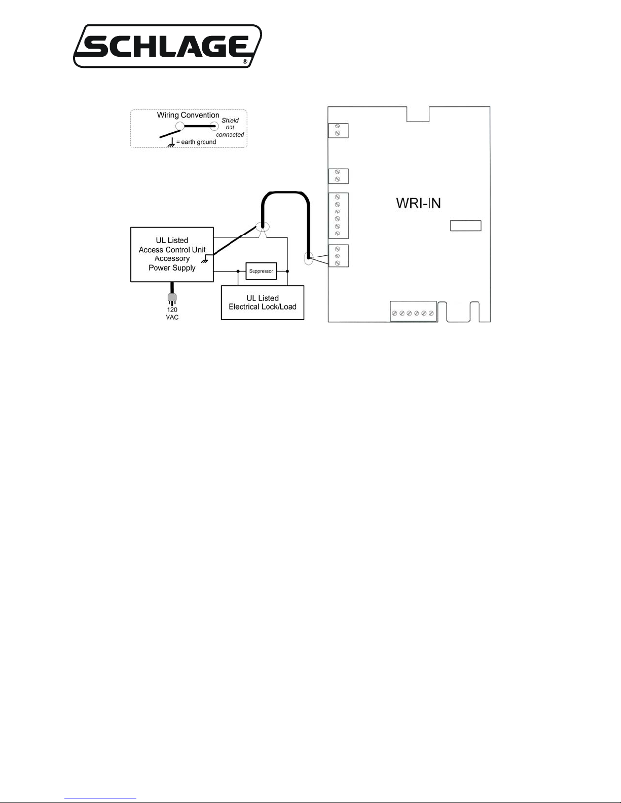
A Suppressor must be installed with every electrical switching device run through the Portal Output
relay contact. The Suppressor protects the WRI-IN from the power generated by the collapsing
magnetic field of an electrical load. The Suppressor will maximize the life of the WRI-IN.
Follow the Electrical Lock/Load manufacturer’s recommendation for suppression of
magnetic/inductive loads. A properly rated bi-directional Tranzorb (Silicon Avalanche Diode) may
also be used. Install the Suppressor within 18 inches of the electrical load (Figure 2-6).
NOTE: The Portal Output must utilize a dedicated shielded cable to prevent transient contamination
of other WRI-IN signal wiring. Do not run the Portal Output wires in the same cable or conduit as any
other WRI-IN wiring. The Portal Output wiring should be at least 12 inches away from any other
WRI-IN wiring or it should be run in a separate conduit.
Connect the shield of the Portal Output cables to the appropriate WRI-IN J7-6 terminal (GND). Do
not connect the cable shield at the Electrical Lock/Load (Figure 2-5).
Wireless Access
Ingersoll Rand Security Technologies
245 W. Roosevelt Road, Bldg 7, Suite 48, West Chicago, IL 60185 / (800) 313-2962 / (630) 293-4257 fax
P/N: M053-014-C www.ir-swa.com Page 13 of 18
Figure 2-6 – Portal Output Suppression Diagram

Wireless Access
Ingersoll Rand Security Technologies
245 W. Roosevelt Road, Bldg 7, Suite 48, West Chicago, IL 60185 / (800) 313-2962 / (630) 293-4257 fax
P/N: M053-014-C www.ir-swa.com Page 14 of 18
2.5.5 Card Reader/Keypad
Any input device with a Wiegand or Clock & Data bit stream can be used with the WRI-IN. A
transaction must be a single bit stream of between 4 and 255 bits.
The WRI-IN provides a Card Reader interface. Wiring of the Card Reader is optional based on the
WRI-IN application.
Take the power requirements of the Card Reader into consideration when sizing the power supply for
the WRI-IN and its peripherals (Section 2.5.1).
Card Reader connections are shown in Table 2-5.
Connect the Card Reader cable shield to the WRI-IN GND terminal on the Card Reader connector.
Do not connect the cable shield at the Card Reader (Figure 2-5).
CLK/D1
DATA/D0
Card Reader inputs, each input line has a 3.3k pull up resistor
to 5V, and a 12V transient suppressor to GND.
12VDC+
GND
Reader power supply output. The WRI-IN PC board routes its
own power supply input to these terminals, so the readers see
the same supply as the WRI-IN. If other than 12 VDC is
required for the input device, then a separate input device
power supply must be used. Make certain that a common
ground connection is established between the input device’s
power supply and the WRI-IN.
GRN_LED Green LED signal line. This signal goes to ground through
100ohm when activated. When deactivated, it is pulled up to
+5V through 1.1kohm.
CARD
READER
RED_LED Red LED signal line. Same functionality as GRN line, except
RED.
Table 2-5 – Card Reader Connections

Wireless Access
Ingersoll Rand Security Technologies
245 W. Roosevelt Road, Bldg 7, Suite 48, West Chicago, IL 60185 / (800) 313-2962 / (630) 293-4257 fax
P/N: M053-014-C www.ir-swa.com Page 15 of 18
3. WRI-IN Cable/Wire Specifications
Application Part Number AWG Description Maximum
Distance
DC Power
Input Belden 8760 18 2 conductor 1,000’
Tamper Belden 8760 18 twisted pair
shielded 2,000’
Request to
Enter Belden 8760 18 twisted pair
shielded 2,000’
Request to
Exit Belden 8760 18 twisted pair
shielded 2,000’
Door Position
Switch Belden 8760 18 twisted pair
shielded 2,000’
Strike
Relay Output Belden 8760 18 twisted pair
shielded 2,000’
Card
Reader Alpha 1296C 22 6 conductor
shielded 500’
Table 3-1 – WRI-IN Cable/Wire Specifications
This completes the installation of the WRI-IN.
If the Wireless Panel Interface Module (WPIM) that will control this WRI-IN is not
installed, now is the time to install it, please refer to the “PIM Installation Instruction”
manual.
If the WPIM is installed, then you are ready to link and configure your Schlage Wireless
Access System, please refer to the “Configuring & Operating a Schlage Wireless Access
System” manual.

Wireless Access
Ingersoll Rand Security Technologies
245 W. Roosevelt Road, Bldg 7, Suite 48, West Chicago, IL 60185 / (800) 313-2962 / (630) 293-4257 fax
P/N: M053-014-C www.ir-swa.com Page 16 of 18
4. Contacting Technical Support
For questions regarding Schlage Wireless Access:
www.ir-swa.com
main: 800-313-2962 (630-876-5680)
technical support: 866-322-1237
fax: 630-293-4257

Wireless Access
Ingersoll Rand Security Technologies
245 W. Roosevelt Road, Bldg 7, Suite 48, West Chicago, IL 60185 / (800) 313-2962 / (630) 293-4257 fax
P/N: M053-014-C www.ir-swa.com Page 17 of 18
5. FCC Compliance, ACA Compliance & Warnings
5.1 FCC Compliance
•This device has been authorized by the FCC Rules and Industry Canada.
•This device complies with the limits for a Class B digital device and a Class B intentional radiator,
pursuant to Part 15 of the FCC Rules and with RSS-210 of Industry Canada. Operation is subject to
the following two conditions: (1) This device may not cause harmful interference, and (2) this
device must accept any interference received, including interference that may cause undesired
operation.
•The Schlage Wireless Access System Component must be installed by qualified professionals or
contractors in accordance with FCC part 15.203, Antenna Requirements.
•Do not use any antenna other than the one provided with the unit.
5.2 ACA Compliance
•The Australian version of AUWRI-IN-12VDC has been authorized by the Australian
Communications Authority (ACA).
5.3 UL Compliance
•The Wireless Reader Interface - Indoor (WRI-IN-12VDC) is listed under UL294 as an access control
system accessory.
•Access equipment manufactured and/or sold by Ingersoll Rand Security Technologies, is not rated
for, or intended for use in life safety installations.
•UL listed panic hardware shall be used to allow emergency exit from the protected area.
•UL listed compatible readers: HID, Model PROXPOINT.
•Use an Ingersoll Rand Security Technologies power supply; model 593PI-12DC (UL listed class 2
power supply).
•The Wireless Reader Interface - Indoor (WRI-IN) maximum standby current at 12 VDC is 10mA.
5.4 Warnings
•RF Exposure - To comply with FCC RF exposure requirements for mobile transmitting devices this
transmitter should only be used or installed at locations where there is normally at least a 20 cm
separation between the antenna and all persons.
•Do not co-locate and operate in conjunction with any other antenna or transmitter.
•Changes or modifications not expressly approved by Ingersoll Rand Security Technologies could
void the user’s authority to operate the equipment.

Wireless Access
Ingersoll Rand Security Technologies
245 W. Roosevelt Road, Bldg 7, Suite 48, West Chicago, IL 60185 / (800) 313-2962 / (630) 293-4257 fax
P/N: M053-014-C www.ir-swa.com Page 18 of 18
6. Revision History
Version Date Changes
X001 03/07/02 preliminary in house release for comments
X001.1 03/22/02 made adjusts in text for differences in WRI-IN-12VDC & WRI, added appropriate
figures
X001.2 04/05/02 updated figures
X001.3 05/13/02 added UL changes, corrected grammar errors, changed getting wires in & out
section, added WRI-IN-12VDC/metal minimum distance paragraphs
001 05/16/02 released for publication
002 09/16/03 updated wiring diagram
003 11/26/03 added boilerplate section, added more conditions to best WPIM & WRI locations,
minor edits to Mounting WRI-IN-12VDC section, changed strike relay specs (table
2-4), enhanced specs for card readers, added statement about using external card
reader power supplies
004 02/20/04 added UL required maximum standby current specification
A 11/02/04 Changed Logo
B 05/17/05 Changed various nomenclature and contact info throughout manual.
C 09/27/06 made minor edits and corrections, updated pictures, added Schlage logo, changed
Ingersoll-Rand to Ingersoll Rand, changed Security & Safety to Security
Technologies, removed address from cover page, changed wyreless to wireless,
removed all ™’s, changed www.wyrelessaccess.com to www.ir-swa.com, changed
technical support # to 866-322-1237, added Australian model number: AUWRI-
IN-12VDC, changed WRI-IN-12VDC references to WRI-IN where reference
applies to both WRI-IN-12VDC & AUWRI-IN-12VDC
This manual suits for next models
1
Table of contents
Other Schlage Wireless Access Point manuals


