Schleicher ASH-26 User manual

The ASH-26 manufactured by Schleicher, is a high performance open class (18m)
glider.
Thank you for your purchase this up-to-date sport semi-scale glider model,
designed for slope soaring, where you will appreciate it´s maneuvereability and
nice flying characteristics. The HQ airfoil offers very smooth and forgiving flying
characteristics. It is all fiberglass sailplane. The major components are built.
The model is designed to be used by advanced modelers.
Kit includes:
* fiberglass fuselage,
All fiberglass 1/6 scale sailplane
ASH-26
Building instructions
3000 mm 1250 g (empty)
1160 mm HQ 3/15
29,8 dm2 A, E, R, F, B

* fiberglass wing, double-high airbrakes installed,
* horizontal stabilizer,
* rudder,
* canopy,
* canopy frame,
* wing connecting rod,
* bag with accessories
* stickers,
* building instructions
To finish the model you need:
* cyanoacrylate adhesive,
* 5-min epoxy glue,
* common modeller’s tools (sharp knife, drilling machine, screwdriver, fine round file,
sandpaper)
To fly you need:
* 6 channel RC set and 8 servos (at least 7 of them micro size)
Attention! Thank you to contact Composite RC Gliders immediately, if you note a missing part
or a damaged part. Composite RC Gliders cannot control the dexterity of the modeler and
cannot influence the builder during the assembly or the use of this radiocontrolled model, thus
Composite RC Gliders will in no way accept or assume responsability or liability for damages
resulting from the use of this user assembled product.
You are responsible for running this model. A damage to property or health might arise by
improper use of this product. This is why you have to keep a safe distance from the buildings and
other developed areas when flying. Make sure that you are the only one who is flying on the
same waveband.
The product may only be used by the children over 14, supervised by adults.
The purchaser/user accepts all the responsibilities in the event of structural or mechanical
problems.
Warning, this is not a toy!
FINISHING THE MODEL

The glider is ready to fly right after the installation of the RC set..
1. How to install the rudder servos
Glue the servo holder plate into the fuselage. Insert the 0.8 mm steel wire with inner tubes into
the outer bowdens. Cut the bowden tube to the proper length, insert it into the fuselage. Check if
all bends are smooth and glue the bowden in several points. Push in the steel wire of 0.8mm
diameter, cut to the proper length. Remove the wire again, solder the brass metal ending and
screw in the link, which will be later connected to the rudder horn.
The rudder is mounted on clip-on hinges. Cut out the notches for rudder hinges with a razor
blade, insert the hinges inside, fixing them with a lean instantaneous cement. Clip the rudder to
hold.
Find the position of the rudder control horn so that the straight line connecting the holes in the
horn and the axis of rotation of the control surface is perpendicular to the surface of the stabilizer
and the horn itself is in the same level as the control wire coming from the fuselage. Glue the
rudder horn. The rudder is controlled by a pull-wire drive. Attach the terminals to the rudder and
join them with a servo using a pull-wire drive.
2. How to install the elevator servos
The rudder is mounted on clip-on hinges. There is an opening for a servo in the steven. Glue up
the servo in the rudder. Glue up the control lever on the elevator flap and join it using a draw rod
with the servo. Connect the servo with the radio using an extension cable. Clip the rudder to
hold.

3. How to install the aileron and flaps servos
Insert the extension cables into the wing and connect them to the servos. It is recommended to
solder these two cables instead of just using connectors. If soldering, take care to the isolation of
the single wires. Attach the control horns to the ailerons and flaps. Fix the ailerons and flaps in
the neutral position using a piece of self-adhesive tape. Install single levers to the servos, adjust
the neutral position and insert the servos into the openings - not fixing them yet. Prepare 4 rods
made of 1,5 mm wire with a „Z“- bend on one end, measure and cut the wires to the proper
lengths, put on pieces of the white bowden and fix the endings as described above (cyanoacrylate
+ pressing). Screw in the clevises. Remove the servos, insert the „Z“-bends into the servo levers,
and glue the servos in the openings using 5-min epoxy. Connect the pushrods to the control
horns. Attach the servo covers using a double-sided self adhesive tape.
4. How to install the servos to the brakes
Attach the servos with two-sided Scotch tape to the channel and join them with the dive flap
using a draw rod. You will need extension cables and a Y-cable.
Shade your spoiler by pushing slightly with a small flat screwdriver on the arms of the bar (black
parts). Pull the Z of the manoeuvring on the gilded part and insert it into the interlocking hole
connecetd with the bottom of the servo. Shade again your spoiler and screw down your clevis at
the end of the manoeuvring. Demonstrate your servo heeding that the manoeuvring arm of the
servo is in the position of closed spoilers of your radion manoeuvring. (Example full gas on the
way of the engine manoeuvring of your radio) Adjust your manoeuvring and glue your servo
after having checked that both spoilers servos are moving in the right direction. Cover the servos
with the sheet.

5. How to install the radio and batteries
Insert the batteries, power switch and receiver in the fuselage .Connect all the servos in the
fuselage with the radio. Use a Y-cable to connect the aileron servos to one channel only or use
two channels, if available, for ailerons. Use a Y-cable to flaps servos and brakes servos.
Use foam to protect them from vibrations and impacts. Connect all components as necessary.
6. Fitting the cockpit
Cut out the canopy transparent section using the mark line, glue it onto the epoxy frame, trim it
then and grind a bit off to a desirable shape.
The canopy is held in place with a pin and canopy lock. Bore then the matching holes in the
fuselage and in the canopy frame. Glue the pin in the front canopy frame. Glue the canopy lock
in the fuselage.
7. Assembling and finishing the model
The wing halves can be secured in the right position either by self-adhesive tape or using a
rubber ring. In this case make 1.8 mm holes in the first wing ribs and screw in the hooks for the
fixing rubber ring. Drill the holes in the proper position in the fuselage for the rubber ring.
Applying the decorative stickers is the last step to finish your model.

Balance: Check the centre of gravity position. This is a very important relationship between the CG
location and the stall characteristics of an airplane or knife-edge performance. CG location determines
the stall characteristics.
CG range from 42 to 47mm measured from the leading edge at the root of the wing.
In workshop, ready to fly, carry the model on the fingers on each side of the fuselage at the wing
root, after having drawn the balance marks.
If the model leans forwards (nose heavy), move the battery backwards.
If the model leans backwards (tail heavy), move the battery forwards, add some lead if
necessary.
The plane is correctly balanced when it leans very slightly forwards with the index on the
reference marks.
FLYING
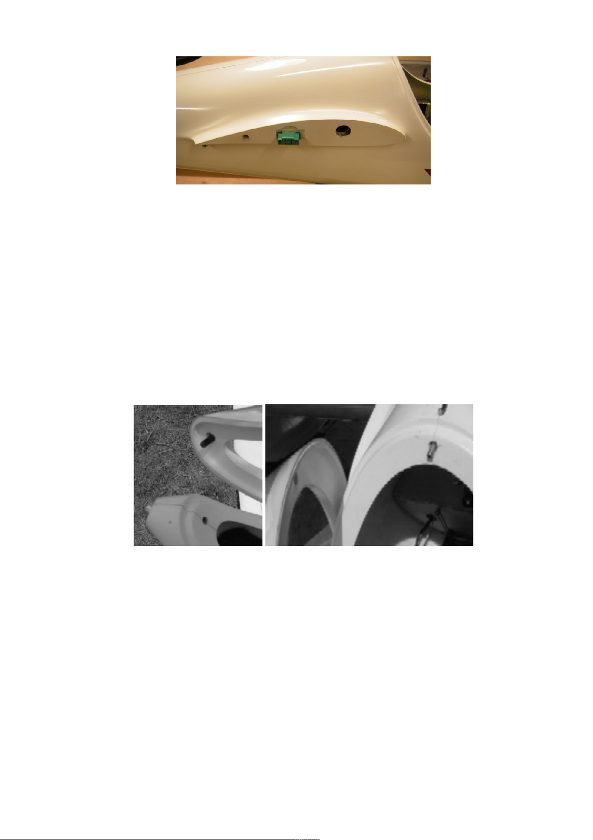
Insert the wing joiner into one wing, then into the fuse and add the other wing. The dowels
ensure the correct incidence of the wings. You can use a white or clear tape to attach the wings
to the fuse, only at upper side.
Don`t forget to check the symmetry of the whole model. Once on the field, first check the
function of your RC set and check the range, too. Calm wheather is the best for the first flights.
Try hand launching, trim if required for optimal gliding. Provided that everything is in order, you
can go for the maiden flight, with a charged battery of course.
Besides the slope soaring it is possible to install a tow hook and use a set for high-altitude
launches for thermal sparing.
Set up:
Rudder function: +/- 30 mm
Elevator function: +/- 6 mm
Aileron function: +12/-5 mm, term flight -1mm
Flaps: crossing +2 mm, term flight -2 mm
Butterfly: flaps -15 mm, ailerons +8 mm, elevator -2 mm
Centre of Gravity: usually 42-47 mm from wing leading edge
Have a lot of fun and many happy landings with your ASH-26

Table of contents
Other Schleicher Toy manuals
Popular Toy manuals by other brands

Hasbro
Hasbro Transformers Energon SCORPONOK manual

PlaSmart
PlaSmart PlasmaCar Assembly

GraviTrax
GraviTrax Pro Starter-Set Vertical GX26832-0 Assembly instructions

ADEEPT
ADEEPT 3WD Bluetooth Car Kit manual

Hasbro Gaming
Hasbro Gaming Rocket Games PieFace Sky High! quick start guide

Hasbro
Hasbro Transformers Animated Autobot Jazz... instructions

Little Tikes
Little Tikes 612428 Assembly instructions

Mega Construx
Mega Construx Call of Duty DYD74 instructions

Rail King
Rail King SANTA FE STEEL RAIL FREIGHT HAULER 2-6-0 operating instructions

Astrid
Astrid Songs of war Iron Heart manual

LEGO
LEGO City 60078 Building instructions

Oxy Heli
Oxy Heli OXY4-MAX Edition 380 instruction manual