Schloder SESD 200 User manual

OPERATION MANUAL
ESD - GENERATOR
SESD 200

User manual SESD 200 page 2
OPERATION MANUAL
ELECTRO STATIC DISCHARGE
GENERATOR
SESD 200
130707
Warning:
This unit generates high voltages and is inherently dangerous. The local, national and all applicable
safety regulations must be obeyed for operation of this unit. The device must only be used by
experienced electric technicians, see VDE 0140. People using cardiac pacemakers should be excluded
from the test area.
Before using the generator please read this manual
and also the warnings to the safety points under item 1

User manual SESD 200 page 3
Contents
1. SAFETY REGULATIONS ..................................................................................................................4
1.1. WARNINGS ...........................................................................................................................................4
1.2. REDUCTION OF SAFETY .........................................................................................................................4
2. INTRODUCTION ................................................................................................................................5
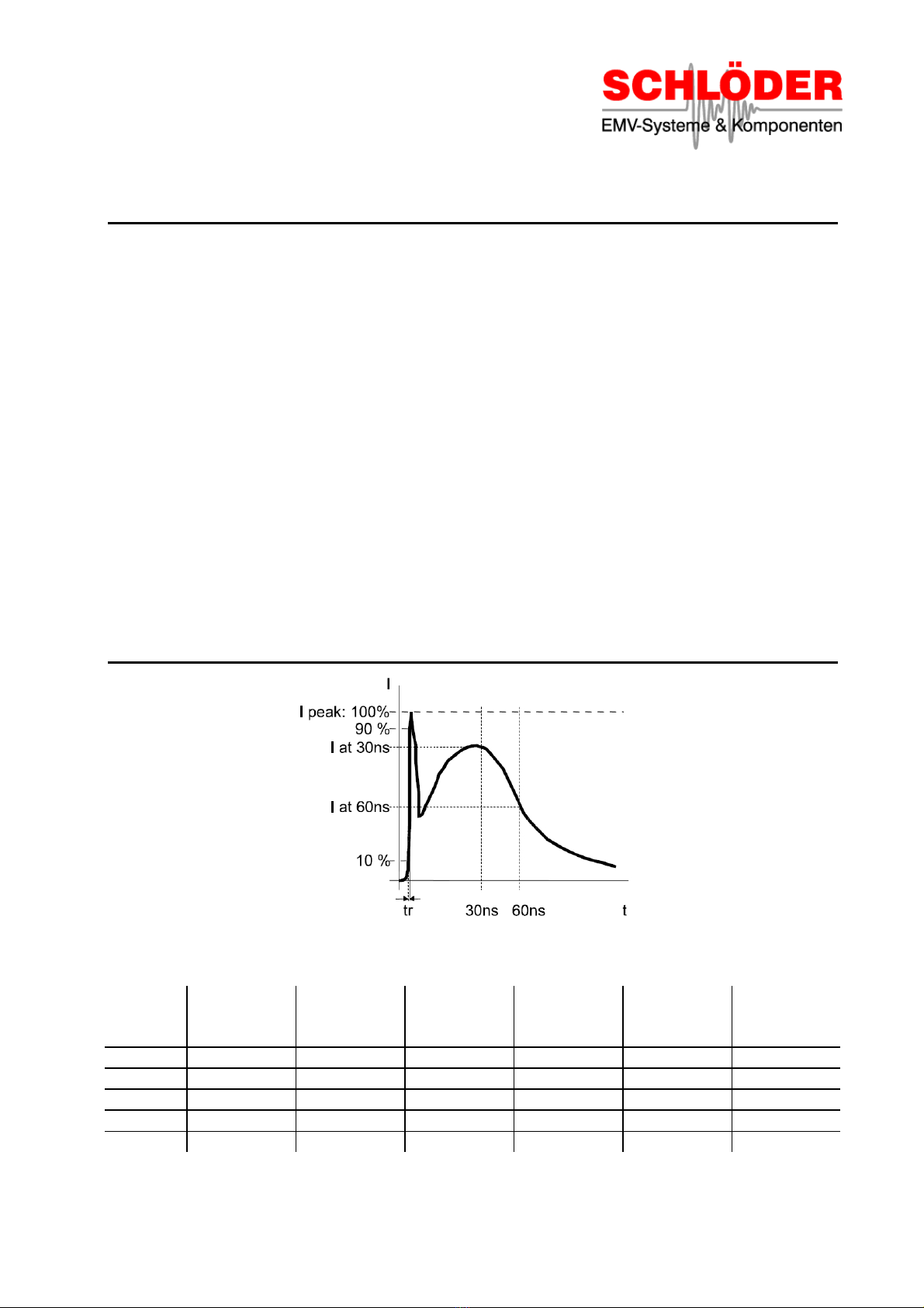
3. ESD - DEFINITION.............................................................................................................................5
4. UNIT FUNCTIONS .............................................................................................................................6
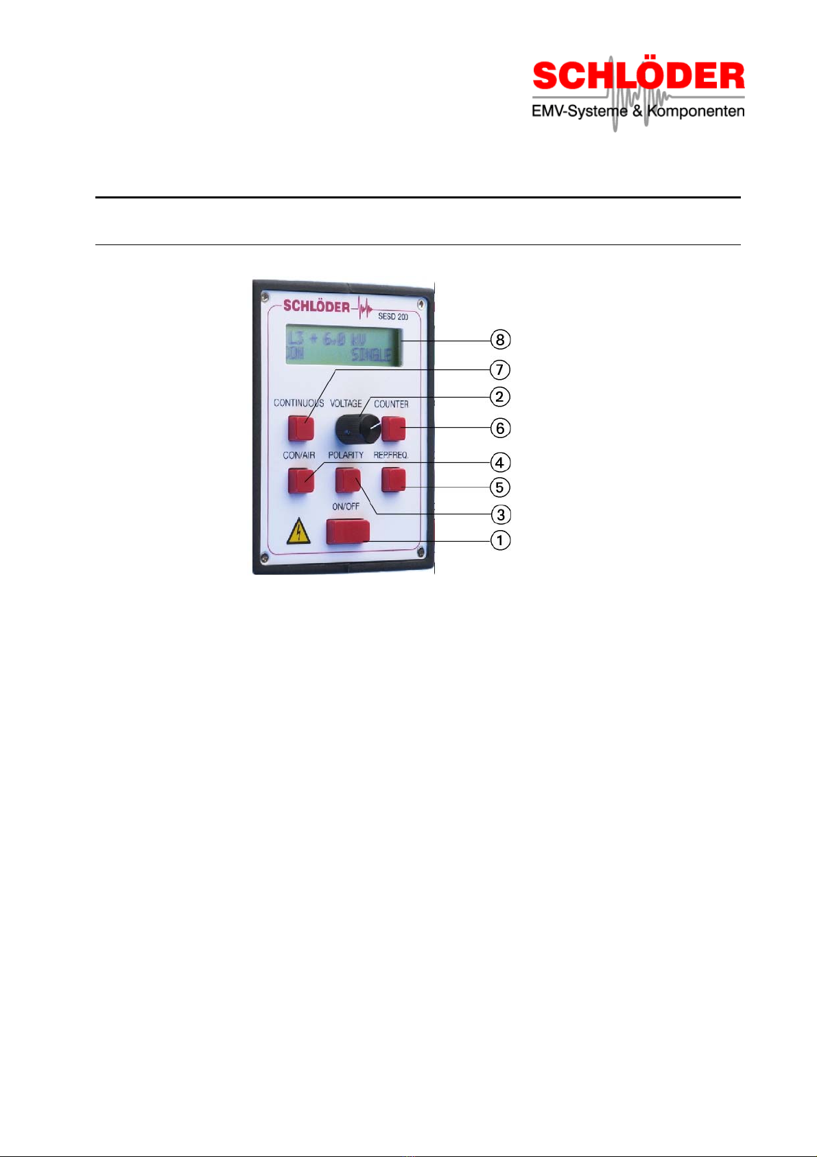
4.1. FRONT PANEL FUNCTION .......................................................................................................................6
4.2. CASE ...................................................................................................................................................7
4.3. POWER SUPPLY ....................................................................................................................................7
5. DESCRIPTION OF FUNCTION .........................................................................................................8
5.1. ON /OFF -SWITCH ..............................................................................................................................8
5.2. OUTPUT VOLTAGE ADJUST.....................................................................................................................8
5.3. POLARITY .............................................................................................................................................8
5.4. MODE CON /AIR.................................................................................................................................9
5.4.1. Special function contact control ..................................................................................................9
5.4.2. Discharge voltage at AIR discharge............................................................................................9
5.5. REPETITION FREQUENCY .......................................................................................................................9
5.6. ADJUST PRE-SELECT COUNTER ...........................................................................................................10
5.7. CONTINUOUS DISCHARGE ....................................................................................................................10
5.8. LCD -DISPLAY...................................................................................................................................10
5.9. TRIGGER KEY......................................................................................................................................10
5.10. DISCHARGE RETURN CABLE .............................................................................................................10
5.11. DISCHARGE ELECTRODES FOR CON /AIR .......................................................................................11
5.12. CONNECTOR POWER SUPPLY ...........................................................................................................11
5.13. CONNECTOR FOR A TRIPOD..............................................................................................................11
5.14. ADJUST THE CONTRAST OF THE LCD -DISPLAYS .............................................................................11
5.15. SERIAL NUMBER ..............................................................................................................................11
5.16. GENERATOR RESET ......................................................................................................................11
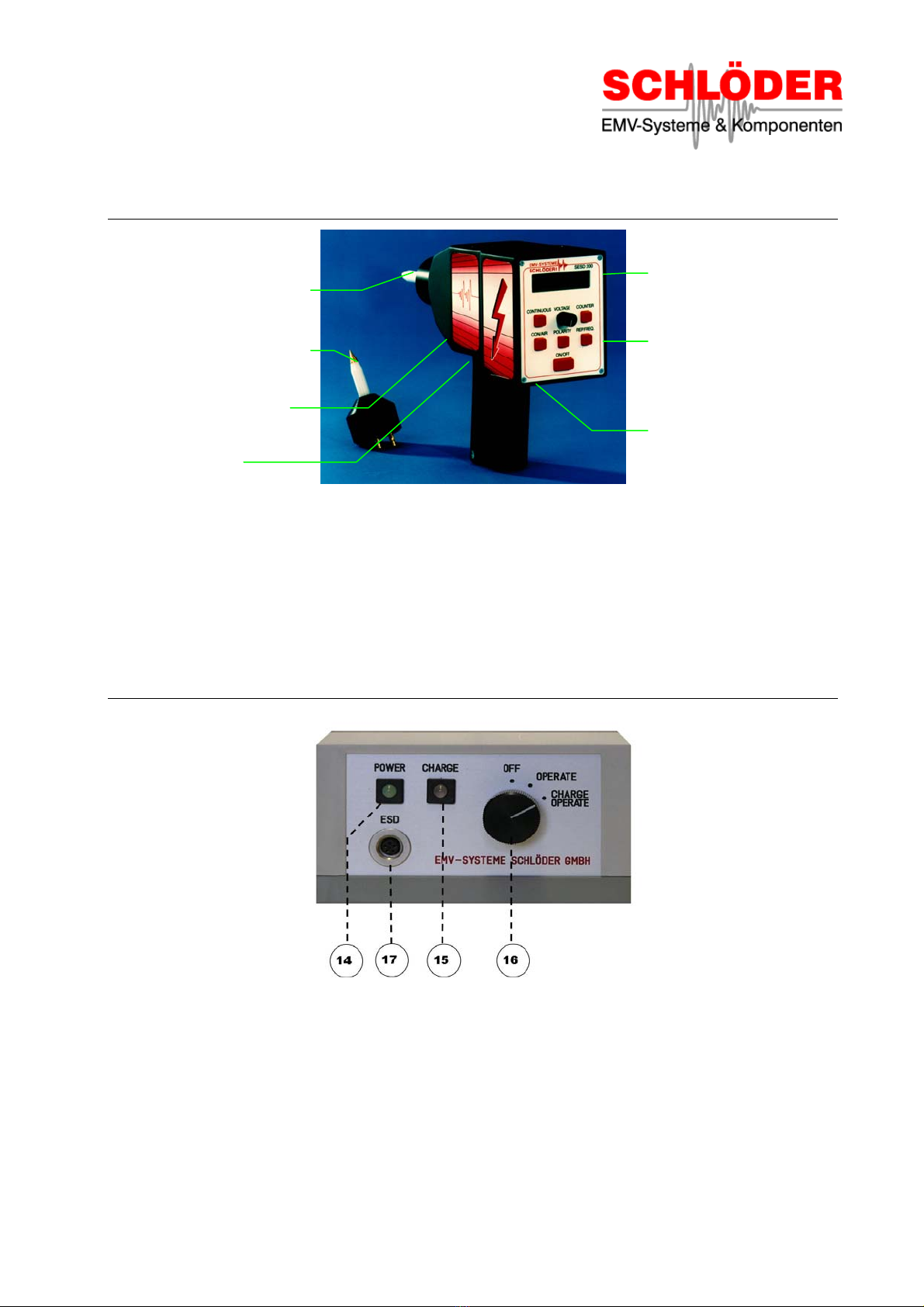
6. POWER SUPPLY.............................................................................................................................12
6.1. CONNECTOR ESD GENERATOR ...........................................................................................................12
6.2. FUNCTION SELECT SWITCH ..................................................................................................................12
6.3. POWER -LED ..................................................................................................................................12
6.4. CHARGE -LED ................................................................................................................................12
7. CALIBRATION.................................................................................................................................13
7.1. TEST EQUIPMENT FOR THE CALIBRATION MEASUREMENT.......................................................................13
7.2. PROOF OF THE QUALITY OF THE ESD PULSE ........................................................................................13
8. ESD TEST FIELD.............................................................................................................................14
8.1. ABOUT WHAT'S WRITTEN IN THE STANDARD ..........................................................................................14
8.2. RECOMMENDATION FOR THE SET-UP OF A TESTING CORNER..................................................................15
9. TECHNICAL DATA..........................................................................................................................16
9.1. GENERATOR .......................................................................................................................................16
9.2. AIR -/CONTACT DISCHARGE ...............................................................................................................16
9.3. POWER SUPPLY ..................................................................................................................................16
10. SCOPE OF DELIVERY ....................................................................................................................16
11. BLOCK SCHEMATIC DIAGRAM ....................................................................................................17

User manual SESD 200 page 4
1. Safety regulations
1.1. Warnings
The test generator SESD 200 creates high voltage up to 16.500 Volts. The energy of this high voltages is
limited, but injury might be incurred if the probe tip is touched.
The handling of the generator is only allowed to experienced and instructed persons according to DIN
570105 / VDE 0105 part 1. Persons with a cardiac pacemaker are not allowed to handle this unit.
The use of the ESD generator assumes, like all measurement tasks and verifications, that the local and
branch specific directions are considered. Precautions should be taken that any part that carries high
voltage and can be touched should be shielded. This is important with both the ESD Generator and the
object under test.
While using the SESD 200 it must be sure that the ground / earth connection is fastened at the
generators ground and connected to earth potential.
The interference generator SESD 200 is according to its specifications designed only for
laboratory use in the industrial surrounding (tests in an Faraday’s cage).
1.2. Reduction of safety
If the unit has visible damage so that a save operation is no longer possible, it has to be set out of
operation. It has to be ensured against unauthorised usage. The unit has to be send immediately to the
manufacture / dealer with a description of the damage!
We warn against untrained staff opening the unit. There is high voltage inside EVEN WHEN
SWITCHED OFF. Your warranty will be void if the unit is opened.

User manual SESD 200 page 5
2. Introduction
The test generator SESD 200 simulates "Electrostatic Discharge" as defined in the standard IEC /EN
61000-4-2. The standard shows two test modes:
a) Air discharge
The discharge electrode with the domed point should first be connected to the SESD. The high voltage
discharge of the generator is into an air gap. The test voltage can be varied from 200 V to 16,500 V. The
very short rise time of each single pulse generates a wide RF spectrum and interference’s.
b) Contact discharge
The discharge electrode with a sharp point is connected to the EUT. The discharge switch is operated by
a vacuum relay allowing a better reproduction of the test results.
Important ! If the probe is not in contact with the EUT (e.g. varnished or oxidised surfaces) there will be
no triggering of impulses. The display will show "NO contact". This item makes sure that a discharge took
place in the contact discharge mode.
Important ! The approach at air discharge has to be started from a distance of at least 20 cm, otherwise
there is the danger of multiple discharge at the single shot mode (discharge voltage can't rise high
enough and is recharged).
You can use the generator either with the built in batteries or with the mains operated power supply.
3. ESD - Definition
Drawing 1
level
test voltage
air discharge
test voltage
contact dis.
rise time
(contact dis.)
1. peak
current
( ±10 %)
current after
30 ns
(±30 %)
current after
60 ns
(±30 %)
1 2 kV 2 kV 0,7 - 1,0 ns 7,5 A 4 A 2 A
2 4 kV 4 kV 0,7 - 1,0 ns 15,0 A 8 A 4 A
3 8 kV 6 kV 0,7 - 1,0 ns 22,5 A 12 A 6 A
4 15 kV 8 kV 0,7 - 1,0 ns 30,0 A 16 A 8 A
X* special special
* Level "X" is an open level.
Table 1: Severity level and waveform parameters at contact discharge

User manual SESD 200 page 6
4. Unit functions
4.1. Front panel function
Drawing 2
1ON / OFF - switch
2Potentiometer output voltage adjust and special function
3Polarity of the pulse, positive and negative
4Mode CON / AIR - contact discharge or air discharge
5Repetition frequency
6Counter pre-selectable
7Continuous discharge
8LCD - Display

User manual SESD 200 page 7
4.2. Case
Drawing 3
4.3. Power supply
Drawing 4
[14] POWER - LED (green)
[15] CHARGE - LED (yellow / red)
[16] Function select switch for line using or charging
[17] Connector to ESD generator
[9] Trigger key
[10] Connector for the
discharge return
cable
[11] Discharge electrodes
for CON
[11] Discharge electrodes
for AIR
[12] Connector for the
power supply
[18]Connector for an optical
RS 232 Converter
[13] Connector for a tripod

User manual SESD 200 page 8
5. Description of function
5.1. ON / OFF - switch
After switching on the generator the LCD display shows the last used parameters. In accumulator mode
the generator should be switched off after usage.
5.2. Output voltage adjust
With the potentiometer the output voltages amplitude can be adjusted in the range of:
± 0,2 kV to 16,5 kV with test method "air discharge".
± 0,2 kV to 9,0 kV with test method "contact discharge".
The voltage value is shown in the upper line of the LCD display. The voltage can be changed in steps of
100 Volts by turning the potentiometer slowly. Turning the potentiometer fast will increase the voltage
steps.
On the left hand of the voltage display the respective test level "L1" to "L4" is shown.
5.3. Polarity
Referring to the standard tests the electrostatic discharges have to be tested in positive (+) and negative
(-) polarity. The display shows the chosen polarity on the left hand of the voltage value, "+" or "-".

User manual SESD 200 page 9
5.4. Mode CON / AIR
With this key the test mode can be changed between contact discharge and air discharge. While pressing
the key the display shows in the lower line the information "CON" or "AIR". Simultaneously the admissible
voltage ranges are changed - see point [5.2]. If the voltage display shows a "standard test level" like L1,
L2, L3 or L4 the voltage is changed according to the test modes specification.
Example: test mode CON test level L3 = + 6.0 kV.
test mode AIR test level L3 = + 8.0 kV.
Make sure that the right test tips are connected to the generator - air discharge "round" and contact
discharge "sharp".
5.4.1. Special function contact control
If the test mode is set to "CON" the triggering can only be released if the serial resistance in the test
circuit is smaller than 4 MΩ. In other cases the display shows "NO CONTACT".
At the level < 1 kV the display doesn’t show "NO CONTACT". Notice, in this case a discharge will be
done.
If you don’t want the function “contact control”, with the service menu you are able to switch ON and OFF
this function. Please ask the manufacturer or your dealer.
5.4.2. Discharge voltage at AIR discharge
In the test mode “AIR” and “Single” the “real discharge voltage” we can show in the display.
After the discharge and hold on the trigger key [9] the voltage in the display changes from the adjusted
voltage to the real discharge voltage. This voltage is shown as sparkled information.
For example:
Adjusted voltage: 12.0 kV -> after the discharge the value 9.7 kV is flashing.
That means the value 9.7 kV is the different value between the adjusted voltage (12.0 kV) and the
residual voltage of the discharge capacitor (2.3 kV)
5.5. Repetition frequency
By pressing the key a number of times the following repetition frequencies (shown on the right hand in the
lower line of the display) can be chosen.
Air discharge: SINGLE or REP (single pulse or repeated).
Contact discharge: SINGLE, 1 Hz, 2 Hz, 5 Hz, 10 Hz or 20 Hz.

User manual SESD 200 page 10
5.6. Adjust pre-select counter
After pressing the key the display shows "COUNTER SET CXXXX". The last selected value appears,
e.g. C1400. Using the potentiometer [2] the value can be changed from C 00 up to C9999. After pressing
the key again the displayed value is fixed in the pre-select counter.
When the charge is released, the counter counts down to zero, then no more impulses are released. For
further usage of the generator, the pre-select counter must either be programmed again or cleared. By
pressing and holding key [6] the pre-select counter will be cleared after the key is released.
5.7. Continuous discharge
For longer tests or if a tripod is used, the generator can be adjusted for automatic continuous discharge.
Operation: press and hold key "CONTINUOUS" [7]. Press trigger key [9].
Release keys [7] and [9]. The function "continuous discharge" is activated.
Switch off: press [9] - the function "continuous discharge" is switched off.
5.8. LCD - Display
The upper line of the two line display shows the test voltage in kV and polarity. The left side of the lower
line gives information about the test mode (CON / AIR), the right side shows the selected repetition
frequency. If the pre-set counter is activated the value is shown in the middle of the lower line.
Special information’s:
a) " BAT ": If this message appears in the upper line on the right hand, the built in battery
needs to be charged. See chapter 6.2.
b) " * " and " _ " : The " * "- sign in the left hand side of the upper line signifies "Attention! High
Voltage" at the test tip. The information is displayed as long as the trigger key [
9] is pressed. After releasing the key [ 9] the sign "_" appears for two or tree
seconds. During this time the high voltage is discharged internally. While the
symbol "_" is displayed, you should not try to change options.
5.9. Trigger key
With the key [9] the discharge is released. There are also special functions that are shown in previous
chapters.
5.10. Discharge return cable
The discharge return cable has to be connected to the ground connector [10]. The other end has to be
connected to ground, either to the ground plane of the test bay or directly to the EUT.

User manual SESD 200 page 11
5.11. Discharge electrodes for CON / AIR
Attention ! Before the discharge electrodes are changed, please switch the generator off and wait
for two or three seconds, so the high voltages can be internally discharged. The discharge
electrodes can be changed simply by pull and insert. Please use the correct electrodes according to the
test modes.
5.12. Connector power supply
The generator is connected to the power supply via the socket [12]. The SESD 200 can be used either
independently, using the built in batteries or while connected to the mains supply. The default usage of
the generator is in the accumulator-supply.
5.13. Connector for a tripod
Normal tripods can be used for continuous testing. The continuous discharge is explained in chapter 5.7.
5.14. Adjust the contrast of the LCD - Displays
Switch OFF the ESD generator. Press the "POLARITY" key [3] and hold down, then press shortly the
"ON / OFF" key [1]. The display shows "ADJUSTMENT OF CONTRAST". With the potentiometer [2] the
contrast can be changed. By pressing the "POLARITY" key again, the new parameters are saved.
5.15. Serial number
Each ESD generator SESD 200 has a serial number written into the software. You can display the
number on the LCD display as follow: Switch OFF the ESD generator. Press and hold down the
“CON/AIR” or “REP/FREQ” key, then press shortly the “ON/OFF” key. The display shows now the serial
number and generator name. This will be displayed for about 10 seconds.
5.16. Generator RESET
If the ESD generator is (during a test) “out to control” the processor unit can be influenced. By pressing
any keys – also ON/OFF – no reaction will come. In the most of cases the solution is a Power Reset of
the SESD 200.
•Connecting the ESD unit with the power supply [see chapter Fehler! Verweisquelle konnte
nicht gefunden werden..]
•Switch the function-select of the power supply to „OPERATE“.
•The power supply is connecting to the main.
•Please wait a little bit, then interupt the power line to the power supply. In this case a power
reset on the CPU is generate.
At least please disconnect the ESD generator from the power supply – the ESD must work as usually.

User manual SESD 200 page 12
6. Power supply
6.1. Connector ESD generator
With connector [17] the ESD Generator is connected to the power supply via this point.
6.2. Function select switch
If switched to "OFF" the power supply is out of operation. There are two possible operation modes:
a) "OPERATE": In this mode the generator is supplied with the required voltage. The batteries in
the generator are not used or charged.
b) "CHARGE OPERERATE"[17]The generator can be used while simultaneously charging the batteries.
Please remember to switch the function selector either "OFF" or "OPERATE"
when the charging period has ended.
6.3. POWER - LED
The green LED [14] indicates the power supply is connected to the mains. There is no requirement for a
fuse. The connection for the earth plane is placed on the rear of the power supply.
6.4. CHARGE - LED
The ESD generator SESD 200 works with a Lithium-Ionen accumulator which has a capacity of 1,3 Ah.
This type of accumulator needs a special charging electronic. A microprocessor controlled IC creates
necessary constant current and constant voltage.
The empty accumulator will be charge with constant current until a battery voltage of 8,2 Volt is reached.
The yellow LED on the power supply is on burning, the charging process needs approximately 45
minutes. The accumulator has now 55% of his capacity.
Now the accumulator charge with constant voltage, the current goes continuously down to 0,2 A. This
charging process needs approximately 45 minutes too and is shown with a yellow blinking LED [15] and a
ratio of 7/8. The accumulator has now more than 80% of his capacity.
After this cycles the accumulator will be charge with 0,1 A, it is shown with the blinking LED [15] and a
ratio of 1/8. At a full accumulator the electronic of the power supply switch off and the lamp is dark.
Please switch the function selector to “OFF” when the charging period has ended.
A charging again is only possible when the function selector [16] is in position “Charge Operate” or the
cable from the power supply to the ESD generator is shortly interrupted. During this handling the LED [15]
burns red / yellow for a short time. The electronic inside the gun check the charging level. A new charging
will be start when the charge current is higher than 0, 25 A.
During each time the charging of the accumulator can be interrupted and can be charge again. The
Lithium-Ionen-Accumulator doesn’t have a “Memory effect”.
Is the LED [15] continuously red or is continuously blinking, the microprocessor recognized a failure in the
power supply.
The power supply is using in a voltage range of 85 V – 264 V AC and in a frequency range of 47 – 63 Hz.

User manual SESD 200 page 13
7. Calibration
7.1. Test equipment for the calibration measurement
Drawing 5
7.2. Proof of the quality of the ESD pulse
The shape of the output current has to be proofed with an oscilloscope with a bandwidth of at least 1
GHz. The test bed has to be set up as shown in the drawing above. For further information’s concerning
the normative probe please have a closer look into the standard IEC 61000-4-2 / EN 61000-4-2.
The most important parameters like rise time and pulse width are defined with a tolerance of ± 30%.
Therefore we recommend a calibration every three years !!

User manual SESD 200 page 14
8. ESD test field
8.1. About what's written in the standard
Drawing 6
Atypical position for indirect discharge to
the vertical coupling plate (VCP)
Btypical position for direct discharge
Ctypical position for indirect discharge to
the horizontal coupling plate (HCP)
1Vertical Coupling Plate (50 x 50 cm)
2Insulation plate
3Horizontal Coupling Plate (160 x 80 cm)
4Resistor’s 470 kOhm
5Ground plane (earth reference)
6Wooden table (h = 80 cm)
7ESD power supply

User manual SESD 200 page 15
In the standard IEC 61000-4-2 / EN 61000-4-2 the set-up of the test bed is described with the drawing
above. Following requirements have to be met:
•The laboratory floor is covered with a earthen ground plane from copper or aluminium with a thickness
of at least 0,25 mm. Other metals may be used with a thickness of at least 0,65 mm. The ground
plane has to rise above the EUT at least 50 cm on each side and must be bigger than 1 m².
•The EUT is set up according to its functions and earthen as desired in the installation instructions.
Further ground connections are not allowed. There must be a distance of one meter between the
laboratory wall and other metal parts.
•The discharge return cable has to be fixed to the ground plane. All ground connections are carried out
low inductive; use for example HF-clamps.
•For tests with indirect discharge use coupling plates with the same material and thickness as used for
the ground plane.
•Testing table sets: the EUT is put on a wooden table with a height of 80 cm. There has to be a
coupling plate of 160 * 80 cm on the table. Between the EUT (including cables) and the coupling plate
an additional insulation of 0,5 mm thickness is found. The coupling plate has to rise at least 10 cm
above the EUT, otherwise a bigger table has to be used.
•Testing bigger EUTs: the EUT with all its cables has to be insulated 10 cm from the ground plane.
8.2. Recommendation for the set-up of a testing corner
Drawing 7
As described above the conformity tests should be made in a Faraday cage. To reduce the expending of
tests in the development we suggest the set-up of a testing corner. Such a corner can be located in the
usual development laboratory or - even better - in the cellar, where the iron-reinforce makes a good
shielding. If the test corner is located in the laboratory it is worth to construct moveable metal screens to
protect other devices in the room. These metal screens are connected (separable) with the ground plane.
•The table with a height of 80 cm has to be all out of wood and must not have any metal parts like nails
or mountings. Such wooden tables can be found typically at local workshops of handicapped people
or prison joiner's workshops.
•The metal plates must be connected with low impedance, either by welding or with copper tape. The
ground plate on the table is connected via 470 kΩ-resistors with the ground plane.

User manual SESD 200 page 16
9. Technical data
9.1. Generator
Output voltage, adjustable:
Mode Air discharge 0,2 kV to 16,5 kV, in steps of 100 V
Mode Contact discharge 0,2 kV to 9,0 kV, in steps of 100 V
Polarity positive and negative
Mode Air - and Contact discharge
Mode of operation single and continuous
Repetition frequency:
Mode Air discharge Single pulse or repeated
Mode Contact discharge Single, 1 Hz, 2 Hz, 5 Hz, 10 Hz or 20 Hz
Counter preselectable 1 - 9999
Contrast of the LCD display adjustable
Operation temperature 0 - 40 ° Celsius
Relative humidity 0 - 60 %
Weight of the generator approx. 1300 g
9.2. Air - / Contact discharge
Discharge electrodes according IEC / EN 61000-4 part 2
Energy storage capacitance 150 pF +/- 10 %
Discharge resistance 330 Ω+/- 5 %
Waveform of the discharge current according IEC / EN 61000-4 part 2
Rise time at Contact discharge 0,7 - 1,0 ns
9.3. Power supply
Supply voltage 85 – 264 VAC / 47 – 63 Hz
Power consumption < 50 VA
Weight approx. 600 g
10. Scope of delivery
•ESD generator
•Power supply with battery charger
•Cable from the power supply to the ESD generator
•Discharge return cable 2 m long
•Discharge electrodes for Contact discharge
•Discharge electrodes for Air discharge
•Operation manual

User manual SESD 200 page 17
11. Block schematic diagram
drawing 8
Address of manufacture:
Schlö d er GmbH
EMV-Systeme & Komponenten
Hauptstrasse 71
D - 75210 Keltern-Weiler
Germany
Tel. : +49 (0)7236 / 9396 - 0
Fax : +49 (0)7236 / 9396 - 90
e-mail : info@schloeder-emv.de
Web : www.schloeder-emv.de
Table of contents