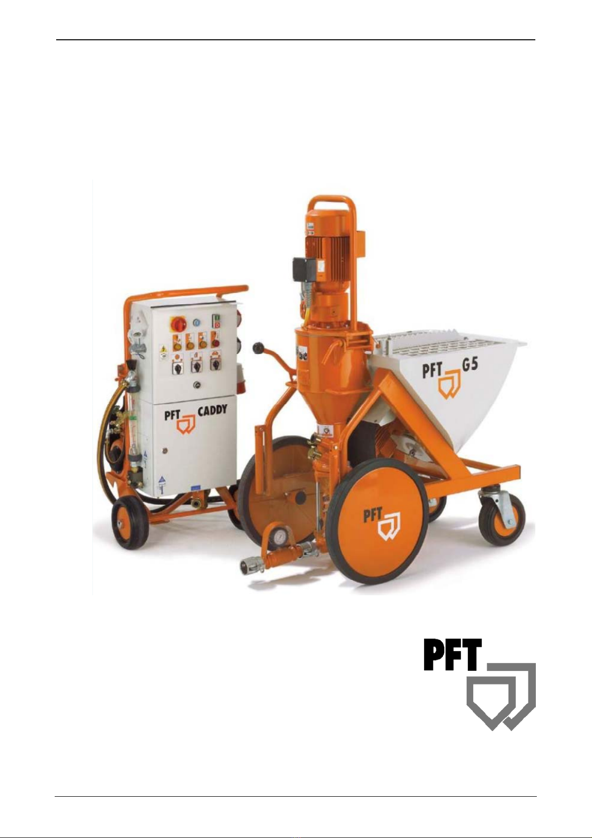
PFT G 5 SUPER Operating Manual Issued 11.2008
Knauf PFT GmbH & Co.KG
4
Contents
Dear PFT customer ....................................................................................................................... 3
Contents ........................................................................................................................................ 4
Applications: .................................................................................................................................. 6
Proper use of the machine ............................................................................................................ 6
Description of functions ................................................................................................................. 6
Dangers and warning symbols ...................................................................................................... 7
Basic safety instructions................................................................................................................ 8
Basic safety instructions................................................................................................................ 9
Signs ........................................................................................................................................... 11
Overview of G 5 SUPER: ltem number 00 00 84 05 ................................................................... 13
Overview of CADDY G 5 SUPER: ltem number 00 00 82 15...................................................... 14
Overview of control box G 5 SUPER: ltem number 00 00 71 34................................................. 15
Overview of water / air manifold .................................................................................................. 16
Technical Specifications.............................................................................................................. 17
Caddy Icons ................................................................................................................................ 18
Settings ....................................................................................................................................... 19
Settings ....................................................................................................................................... 19
Mortar pressure ........................................................................................................................... 20
PFT pump components ............................................................................................................... 20
Checking the conveying pressure and back pressure................................................................. 21
Pump System adjustable............................................................................................................. 22
Start-up........................................................................................................................................ 23
Setting the water factor ............................................................................................................... 25
Procedures at the End of Work and Cleaning ............................................................................. 29
Getting Rid of Hose Blocks ......................................................................................................... 31
Measures for Power Failure and Water Supply Failure............................................................... 31
Measures for Water Supply Failure............................................................................................. 32
Measures for Suzero Temperatures............................................................................................ 32
Transport ..................................................................................................................................... 34
Maintenance................................................................................................................................ 34
Accessories ................................................................................................................................. 35
Fault – Cause – Remedy............................................................................................................. 36
Spare parts list for chassis G 5 SUPER: part no. 00008223....................................................... 38
Spare parts list geard motor / mixing tube................................................................................... 40
Spare parts list pump unit / mortar pressure gauge .................................................................... 42
Spare parts list chassis caddy, compressor K2N and manifold box............................................ 44
Spare parts list water manifold G 5 SUPER: part no. 00008260................................................. 46