Schmalz MATCH User manual

Storage Station MATCH
Mounting instructions
Note
The Assembly instructions were originally written in German. Store in a safe place for future reference. Subject
to technical changes without notice. No responsibility is taken for printing or other types of errors.
Published by
© J.SchmalzGmbH, 06/21
This document is protected by copyright. J.SchmalzGmbH retains the rights established thereby. Reproduction of
the contents, in full or in part, is only permitted within the limits of the legal provisions of copyright law. Any mod-
ifications to or abridgments of the document are prohibited without explicit written agreement from
J.SchmalzGmbH.
J. Schmalz GmbH · Johannes-Schmalz-Str. 1 · 72293 Glatten, Germany · T: +49 7443 2403-0
EN-US · 30.30.01.02781 · 00 · 06/21

Contents
2 / 10 EN-US · 30.30.01.02781 · 00 · 06/21
Contents
1 Important Information ...................................................................................................................................3
1.1 Note on Using this Document ............................................................................................................ 3
1.2 The technical documentation is part of the product ........................................................................ 3
1.3 Type Plate ............................................................................................................................................ 3
1.4 Warnings in This Document................................................................................................................ 3
1.5 Symbol.................................................................................................................................................. 4
2 Fundamental Safety Instructions...................................................................................................................4
2.1 Intended Use........................................................................................................................................ 4
2.2 Non-Intended Use ............................................................................................................................... 4
2.3 Personnel Qualifications ..................................................................................................................... 4
2.4 Modifications to the Product.............................................................................................................. 4
3 Product description.........................................................................................................................................5
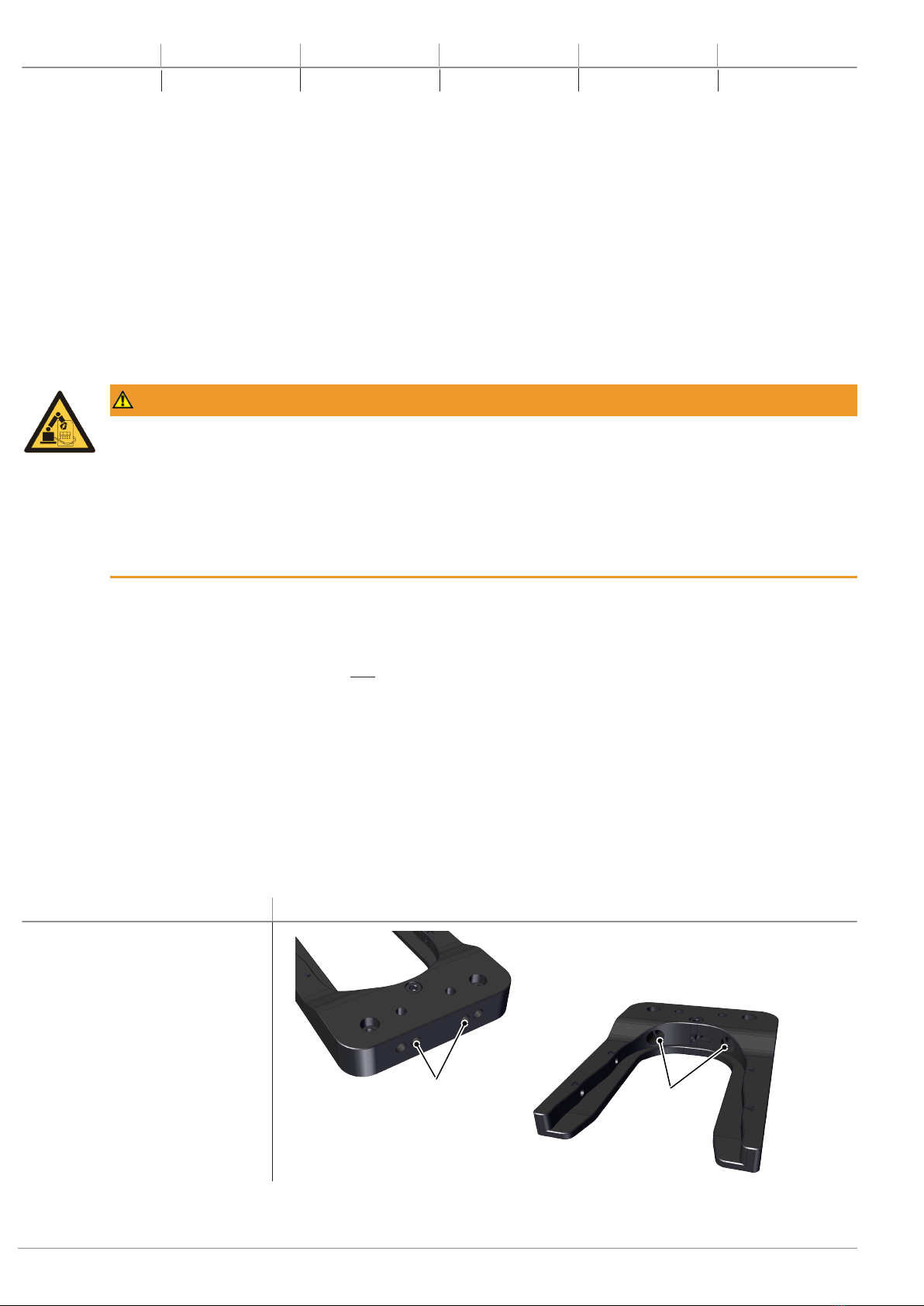
3.1 Product Design .................................................................................................................................... 5
3.2 Description of Functions ..................................................................................................................... 5
3.2.1 Function of the Sensors............................................................................................................... 5
3.2.2 Circuit Diagram for Sensor System .............................................................................................6
3.2.3 Configuration of “Test Position” Sensor....................................................................................7
3.2.4 Configuration of “Storage Position” Sensor .............................................................................7
3.2.5 Functional Safety ......................................................................................................................... 7
4 Technical Data .................................................................................................................................................7
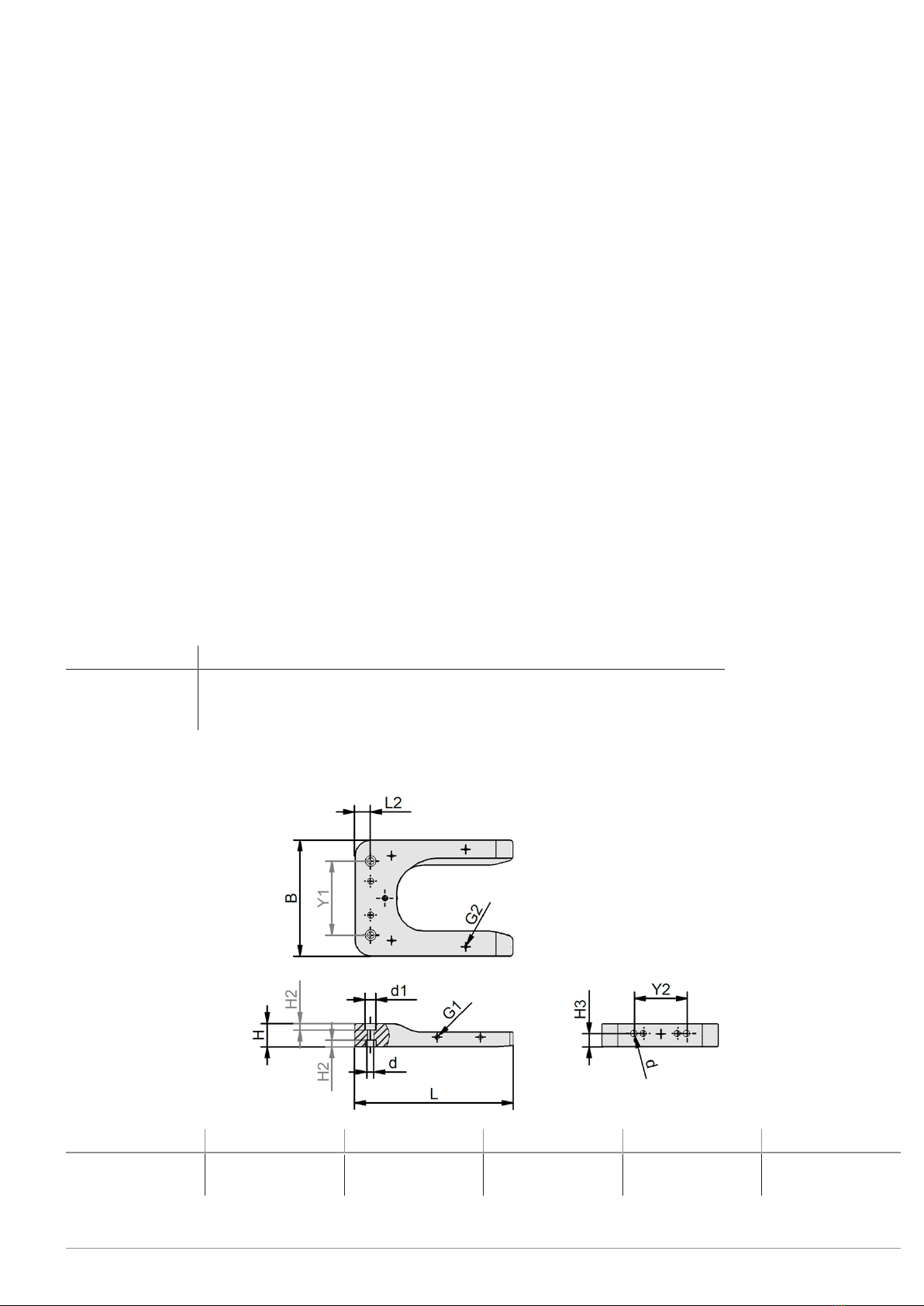
5 Dimensions ......................................................................................................................................................7
6 Checking the Delivery.....................................................................................................................................8
7 Installation.......................................................................................................................................................8
7.1 General Mounting Information.......................................................................................................... 8
7.2 Mounting ............................................................................................................................................. 8
7.3 Initial Setup (Loose Member with Storage Station)........................................................................ 10
8 Maintenance and Cleaning ..........................................................................................................................10
8.1 Maintenance...................................................................................................................................... 10
8.2 Cleaning ............................................................................................................................................. 10
9 Taking the Product Out of Operation and Disposal...................................................................................10
10 Accessories ....................................................................................................................................................10

1 Important Information
1.1 Note on Using this Document
J.SchmalzGmbH is generally referred to as Schmalz in these Assembly instructions.
These Assembly instructions contain important notes and information about the different
operating phases of the product:
• Transport, storage, start of operations and decommissioning
• Safe operation, required maintenance, rectification of any faults
The Assembly instructions describe the product at the time of delivery by Schmalz.
1.2 The technical documentation is part of the product
1. For problem-free and safe operation, follow the instructions in the documents.
2. Keep the technical documentation in close proximity to the product. The documentation must be accessible
to personnel at all times.
3. Pass on the technical documentation to subsequent users.
ðFailure to follow the instructions in these Assembly instructions may result in injuries!
ðSchmalz is not liable for damage or malfunctions that result from failure to heed these instructions.
If you still have questions after reading the technical documentation, contact Schmalz Service at:
www.schmalz.com/services
1.3 Type Plate
The type plate (1) is permanently attached to the prod-
uct at the location shown and must always be clearly
legible.
It contains important information about the product:
• Part sales designation/type
• Part number
• Serial number
• Coded date of manufacture
• CE label
• QR code
1
Please specify all the information above when ordering replacement parts, making warranty claims or for any
other inquiries.
1.4 Warnings in This Document
Warnings warn against hazards that may occur when handling the product. The signal word indicates the level of
danger.
Signal word Meaning
WARNING Indicates a medium-risk hazard that could result in death or serious injury if
not avoided.
CAUTION Indicates a low-risk hazard that could result in minor or moderate injury if
not avoided.
NOTE Indicates a danger that leads to property damage.
EN-US · 30.30.01.02781 · 00 · 06/21 3 / 10

1.5 Symbol
This symbol indicates useful and important information.
üThis symbol represents a prerequisite that must be met prior to an operational step.
4This symbol represents an action to be performed.
ðThis symbol represents the result of an action.
Actions that consist of more than one step are numbered:
1. First action to be performed.
2. Second action to be performed.
2 Fundamental Safety Instructions
2.1 Intended Use
The product:
• shall be mounted on industrial machines and used to hold tools.
• is designed exclusively for depositing loose parts of the MATCH series with or without tools.
• may be loaded with a maximum of 5 kg.
• shall be used for its intended purpose in enclosed spaces.
The product is built in accordance with the latest standards of technology and is delivered in a safe operating con-
dition; however, hazards may arise during use.
The product is intended for industrial use.
Intended use includes observing the technical data and the installation and operating instructions in this manual.
2.2 Non-Intended Use
Schmalz does not accept any liability for any direct or indirect losses or damages that result from using the product.
This applies, in particular, to any use of the product that is not in accordance with the intended purpose and to any
use that is not described or mentioned in this documentation.
The use of the product under extreme conditions (for example, with abrasive fluids or dusts) requires the prior ap-
proval of Schmalz.
In particular, the following are considered non-intended use:
1. Use in potentially explosive atmospheres
2. Direct contact with perishable goods/food products
2.3 Personnel Qualifications
Unqualified personnel cannot recognize dangers and are therefore exposed to higher risks!
1. Task only qualified personnel to perform the tasks described in these Assembly instructions.
2. The product must be operated only by persons who have undergone appropriate training.
These Assembly instructions are intended for fitters who are trained in handling the product and who can operate
and install it.
2.4 Modifications to the Product
Schmalz assumes no liability for consequences of modifications over which it has no control:
1. The product must be operated only in its original condition as delivered.
2. Use only original spare parts from Schmalz.
3. The product must be operated only in perfect condition.
4 / 10 EN-US · 30.30.01.02781 · 00 · 06/21

3 Product description
3.1 Product Design
The product is a storage station according to DIN ISO 13849-1. The basic and proven safety regulations as per DIN
EN 13849-1 can only be adhered to if original parts from Schmalz are used.
2
1
3
4
1 Stop 2 Storage station
3 Attachment and positioning (6x) 4 Sensor attachment (4x) (sensor optional)
3.2 Description of Functions
The storage station is a device in which a fully equipped loose member RMQC is held ready in a defined position.
Several storage stations can hold variously equipped loose members for use with a fixed member.
The loose members and storage station have been designed and developed in such a way that incorrect insertion
of the loose member into the storage station is not possible.
The storage station can be used with or without sensors (for position and safety monitoring).
3.2.1 Function of the Sensors
The figure below shows an example of a combination consisting of a fixed member, loose member with gripper
and storage station.
When the sensor system is used, it checks whether the loose member is present in the storage station.
The fixed member is then moved onto the loose member from above. The centering pins on the loose member
help with insertion. Along with the fixed member and loose member, the robot moves to the “test position”sensor
in the storage station.
The two sensors in the test position (test channel) respond when the locking mechanisms are lowered and are in
contact with the fixed member.
When the fixed and loose members are joined together, the internal spring-pin contacts are connected for signal
transmission.
As a result, the connect LED (3) changes color from red to green and a connect signal (depending on the variant) is
transferred to the higher-level controller.
EN-US · 30.30.01.02781 · 00 · 06/21 5 / 10

6
8
2
7
1
3
5
4
1 Grippers 2 Quick-change system RMQC MATCH loose
member
3 Connect LED 4 Storage position sensor (loose member
present), optional
5 Quick-change system RMQC MATCH fixed
member
6 Storage station MATCH
7 Locking mechanism 8 Sensor test position (locking mechanism low-
ered) 2x, optional
3.2.2 Circuit Diagram for Sensor System
Connection of the M8 3-Pin Sensor Connec-
tor:
Circuit symbol for sensor in storage position Series connection of two sensors in test position
Power Supply
Safety
Input
Power Supply
Safety
Input
Safety
Input
6 / 10 EN-US · 30.30.01.02781 · 00 · 06/21

3.2.3 Configuration of “Test Position” Sensor
1. With the loose member connected to the fixed member, bring the markings on the locking elements into line
with the front markings on the storage station.
2. Screw in the sensors (8) until they emit a signal.
3. Fasten the sensors (8) in this position.
4. Coat the sensors (8) with sealing wax (recommended).
3.2.4 Configuration of “Storage Position” Sensor
1. Place a loose member in the storage station.
2. Screw in the sensor (4) until it emits a signal.
3. Fasten the sensor (4) in this position.
4. Coat the sensor (4) with sealing wax (recommended).
3.2.5 Functional Safety
For overall functional safety, all three components (fixed member, loose member with gripper and storage station)
must be taken into consideration.
The safety function (secure locking between the fixed and loose member) of the product is ensured by two redun-
dant mechanisms (mechanical lock/springs).
Supplementary technical protective measures (sensors) provide a high degree of diagnostic coverage. As a result,
the product has been classified in control category 3 according to DIN EN ISO 13849-1, chapter 6.2.6. According to
Figure 5 in chapter 4.5.4 of the above standard, performance level (PL) d can be achieved with this product.
The fault exclusion according to DIN EN ISO13849-2, annex A, table A2 and A3 for the screw pressure springs used
may be provided.
4 Technical Data
Mass 340 g
Material Main body = polyoxymethylene (POM), black
Stop bolt + attachment (set screw, sleeve, disc) = steel
Label = polyester, silver, matte (PC inscribed plastic film, self-adhesive)
5 Dimensions
B G2 G1 H H2 H3
110 M4 internal
thread
M5x0.5-IG 22 6.2 12.5
EN-US · 30.30.01.02781 · 00 · 06/21 7 / 10

d d1 L2 Y1 Y2 L
6.4 10.4 15 70 50 150
All dimensions given in millimeters [mm].
6 Checking the Delivery
The scope of delivery can be found in the order confirmation. The weights and dimensions are listed in the delivery
notes.
1. Compare the entire delivery with the supplied delivery notes to make sure nothing is missing.
2. Damage caused by defective packaging or occurring in transit must be reported immediately to the carrier
and J.SchmalzGmbH.
7 Installation
7.1 General Mounting Information
WARNING
Risk of injury due to the unexpected movement of the plant or machine in which the prod-
uct is to be installed.
Risk of injury
4Switch off the machine’s power supply before performing any work.
4Secure the machine against unintentional activation.
4Check the machine for possible residual energy.
The product must be mounted on a suitable screw-on surface that meets the requirements for evenness.
The permissible unevenness is: 0.03mm
• You must switch off the power supply before mounting, installation and maintenance work.
• The mounting bolts and dowel pins are not included in the scope of delivery.
• Strength class for the mounting bolts: ≥ 8.8 (DIN EN ISO 4762)
• Schmalz recommends verifying the permissible load capacity of the required screw connections in accordance
with VDI 2230.
In high ambient temperatures, the product must be mounted on heat-dissipating materials. The service life of the
product may be reduced if it is continuously operated under very high ambient temperatures and with rapid clock
cycles.
7.2 Mounting
The product can be mounted via the mounting holes on the mounting structure or on the attachment part. The
product can be mounted from above, below or from the front.
Mounting preparation for... Positions of the dowel pins (PZ) and screws (PS)
... mounting from the front (1)
PZ1 PS1
8 / 10 EN-US · 30.30.01.02781 · 00 · 06/21

Mounting preparation for... Positions of the dowel pins (PZ) and screws (PS)
... mounting from above (2)
PZ3
PS2
PS3
PZ2
... mounting from below (3)
Customer-supplied mounting material:
• 2x dowel pins, ISO 2338, form B (tolerance field h8), Ø6
• 2x machine screws with hexagonal socket, ISO 4762, M6
The lengths of the screws and dowel pins must be determined by the customer, as they depend on the selected
mounting option and on the mounting structure.
During mounting, two holes (size Ø6H7) are required on the mounting structure at a distance of 32 mm for the
dowel pins of the anti-rotation guard.
When using two or more storage stations, a minimum distance of 70 mm (without strain relief) must be main-
tained between the storage stations in order to prevent the sensors from colliding.
The following work steps must be observed during mounting and are explained here using the example of mount-
ing from the front:
üThe customer supplies the required number and type of mounting bolts.
üThe Ø6H7 holes for the dowel pins must be prepared on the mounting structure.
1. Push the dowel pins into the fittings of the storage
station.
2. Position the storage station on the mounting struc-
ture.
3. Fix the storage station with the mounting bolts.
Adhere to the tightening torques of the mounting
bolts.
EN-US · 30.30.01.02781 · 00 · 06/21 9 / 10

7.3 Initial Setup (Loose Member with Storage Station)
When setting up a loose member in the storage station for
the first time, turn the stop pin (1) into the provided recess.
Then “teach” your robot for the required position.
After successful teaching, swivel the stop pin (1) back by 90°
and correct its position if necessary.
1
8 Maintenance and Cleaning
8.1 Maintenance
Product operation is maintenance-free.
Despite this, you must regularly inspect the product for any corrosion, damage and dirt.
When maintaining or cleaning the sensors, observe the manufacturer’s instructions.
8.2 Cleaning
CAUTION
Use of Cleaners Containing Solvents
Damage to the product (seals, insulation, coatings and other surfaces may be damaged by cleaners
that contain solvents) and potentially damage to health
4Use a chemically and biologically neutral cleaning agent.
4Use cleaning agent that is rated as non-harmful to health.
4The use of the following cleaning agents is strictly prohibited:
— Acetone
— white spirit
— cellulose thinner/turpentine oil (solvents)
9 Taking the Product Out of Operation and Disposal
If the product reaches the end of the utilization phase, it may be fully disassembled and disposed of. Only qualified
specialist staff may prepare the product for disposal.
1. Fully disconnect the product from the power supply.
2. Dispose of the components properly based on their material groups.
For proper disposal, contact a company specializing in the disposal of technical goods and instruct the company to
observe the applicable disposal and environmental regulations.
10 Accessories
Part no. Designation Note
21.01.09.00072 Inductive sensor (for storage station) 2 sensors can be mounted opposite each
other for each position
Pos. 1 = test position (front position)
Pos. 2 = storage position (rear position)
10 / 10 EN-US · 30.30.01.02781 · 00 · 06/21
This manual suits for next models
1
Table of contents