schmersal AST LC ST-AS User manual

AST LC ST-AS
Betriebsanleitung
Opto-Tube
DE 1
1. Zu diesem Dokument
1.1 Funktion
Die vorliegende Betriebsanleitung liefert die erforderlichen Informatio-
nen für die Montage, die Inbetriebnahme, den sicheren Betrieb sowie
die Demontage des Sicherheitsschaltgerätes. Die Betriebsanleitung ist
stets in einem leserlichen Zustand und zugänglich aufzubewahren.
1.2 Zielgruppe: autorisiertes Fachpersonal
Sämtliche in dieser Betriebsanleitung beschriebenen Handhabungen
dürfen nur durch ausgebildetes und vom Anlagenbetreiber autorisiertes
Fachpersonal durchgeführt werden.
Installieren und nehmen Sie das Gerät nur dann in Betrieb, wenn Sie
die Betriebsanleitung gelesen und verstanden haben und Sie mit den
geltenden Vorschriften über Arbeitssicherheit und Unfallverhütung
vertraut sind.
Auswahl und Einbau der Geräte sowie ihre steuerungstechnische
Einbindung sind an eine qualifizierte Kenntnis der einschlägigen Ge-
setze und normativen Anforderungen durch den Maschinenhersteller
geknüpft.
1.3 Verwendete Symbolik
Information, Tipp, Hinweis:
Dieses Symbol kennzeichnet hilfreiche Zusatzinformationen.
Vorsicht: Bei Nichtbeachten dieses Warnhinweises können
Störungen oder Fehlfunktionen die Folge sein.
Warnung: Bei Nichtbeachten dieses Warnhinweises kann ein
Personenschaden und/oder ein Schaden an der Maschine
die Folge sein.
1.4 Bestimmungsgemäßer Gebrauch
Die hier beschriebenen Produkte wurden entwickelt, um als Teil einer
Gesamtanlage oder Maschine sicherheitsgerichtete Funktionen zu
übernehmen. Es liegt im Verantwortungsbereich des Herstellers einer
Anlage oder Maschine, die korrekte Gesamtfunktion sicherzustellen.
Das Sicherheitsschaltgerät darf ausschließlich entsprechend der
folgenden Ausführungen oder für durch den Hersteller zugelassene
Anwendungen eingesetzt werden. Detaillierte Angaben zum Einsatzbe-
reich finden Sie im Kapitel „Produktbeschreibung“.
1.5 Allgemeine Sicherheitshinweise
Die Sicherheitshinweise der Betriebsanleitung sowie landesspezifische
Installations-, Sicherheits- und Unfallverhütungsvorschriften sind zu
beachten.
Weitere technische Informationen entnehmen Sie bitte den
Schmersal Katalogen bzw. dem Online-Katalog im Internet
unter www.schmersal.net.
Alle Angaben ohne Gewähr. Änderungen, die dem technischen
Fortschritt dienen, vorbehalten.
Werden mehrere Sicherheitskomponenten in Reihe ge-
schaltet, wird der Performance Level nach EN ISO 13849-1
aufgrund verringerter Fehlererkennung unter Umständen
reduziert. Das Gesamtkonzept der Steuerung, in welche die
Sicherheitskomponente eingebunden wird, ist nach
EN ISO 13849-2 zu validieren.
Inhalt
1 Zu diesem Dokument
1.1 Funktion ..............................................1
1.2 Zielgruppe: autorisiertes Fachpersonal ......................1
1.3 Verwendete Symbolik ...................................1
1.4 Bestimmungsgemäßer Gebrauch ..........................1
1.5 Allgemeine Sicherheitshinweise ...........................1
1.6 Warnung vor Fehlgebrauch ...............................2
1.7 Haftungsausschluss.....................................2
2 Produktbeschreibung
2.1 Typschlüssel ..........................................2
2.2 Sonderausführungen ....................................2
2.3 Bestimmung und Gebrauch ...............................2
2.4 Technische Daten ......................................2
2.5 Sicherheitsbetrachtung ..................................2
3 Montage
3.1 Allgemeine Montagehinweise .............................2
3.2 Abmessungen .........................................2
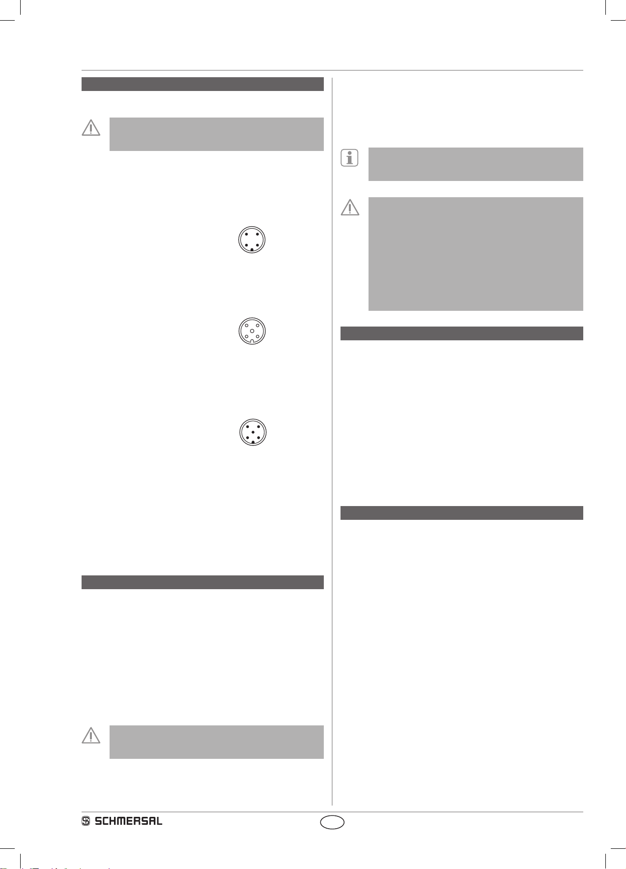
4 Elektrischer Anschluss
4.1 Allgemeine Hinweise zum elektrischen Anschluss .............3
5 Konguration
5.1 Programmierung der Slaveadresse .........................3
5.2 Konguration des Sicherheitsmonitors ......................3
5.3 Statussignal „Sicherheitsfreigabe“ ..........................3
6 Inbetriebnahme und Wartung
6.1 Funktionsprüfung .......................................3
6.2 Wartung . . . . . . . . . . . . . . . . . . . . . . . . . . . . . . . . . . . . . . . . . . . . . .3
7 Demontage und Entsorgung
7.1 Demontage ...........................................3
7.2 Entsorgung............................................3
8 EU-Konformitätserklärung
x.000 / 11.2017 / v.A. - 101182558 / C / 2017-11-23 / AE-Nr. 8410
DE Betriebsanleitung . . . . . . . . . . . . . . .Seiten 1 bis 4
Original
EN Operating instructions. . . . . . . . . . . . .pages 5 to 8
Original
CS Aktuální verzi návodu k použití
ve vašem jazyce naleznete na
www.schmersal.net
DA På www.schmersal.net findes
aktuelle betjeningsvejledninger
på EU's officielle sprog.
ES Encontrará el manual de
instrucciones actual en su
idioma oficial de la UE en
nuestra página de Internet
www.schmersal.net.
FR Vous trouverez la version actuel-
le du mode d’emploi dans votre
langue nationale officielle sur
l’Internet, www.schmersal.net.
IT Il manuale d‘istruzioni aggiornato
nella vostra lingua (lingua ufficiale
UE) è scaricabile in Internet
all‘indirizzo www.schmersal.net.
JP 日本語の取扱説明
書は、インターネット
(www.schmersal.net)から
ダウンロード出来ます。
NL U vindt de huidige versie van
de gebruikshandleiding in uw
officiële landstaal op het Internet,
www.schmersal.net.
PL Tutaj znajdziesz aktualną wersję
instrukcji obsługi w Twoim
języku na stronie internetowej
www.schmersal.net.
PT O manual de instruções actual,
no seu idioma oficial da UE,
encontra-se na nossa página de
Internet www.schmersal.net.
SV På www.schmersal.net finner
ni de aktuella versionerna av
bruksanvisningen på EU’s
officiella språk.
mrl_opto-tube_de.indd 1 23.11.2017 15:56:59

2
Betriebsanleitung
Opto-Tube AST LC ST-AS
DE
Restrisiken sind bei Beachtung der Hinweise zur Sicherheit sowie
der Anweisungen bezüglich Montage, Inbetriebnahme, Betrieb und
Wartung nicht bekannt.
1.6 Warnung vor Fehlgebrauch
Bei nicht sachgerechter oder nicht bestimmungsgemäßer
Verwendung oder Manipulationen können durch den Einsatz
des Sicherheitsschaltgerätes Gefahren für Personen oder
Schäden an Maschinen- bzw. Anlagenteilen nicht ausge-
schlossen werden. Bitte beachten Sie auch die diesbezüg-
lichen Hinweise der Norm EN 1088.
1.7 Haftungsausschluss
Für Schäden und Betriebsstörungen, die durch Montagefehler oder
Nichtbeachtung dieser Betriebsanleitung entstehen, wird keine Haftung
übernommen. Für Schäden, die aus der Verwendung von nicht durch
den Hersteller freigegebenen Ersatz- oder Zubehörteilen resultieren, ist
jede weitere Haftung des Herstellers ausgeschlossen.
Jegliche eigenmächtige Reparaturen, Umbauten und Veränderungen
sind aus Sicherheitsgründen nicht gestattet und schließen eine Haftung
des Herstellers für daraus resultierende Schäden aus.
2. Produktbeschreibung
2.1 Typschlüssel
Diese Betriebsanleitung ist gültig für folgende Typen:
AST LC ST-AS
2.2 Sonderausführungen
Für Sonderausführungen die nicht im Typschlüssel unter 2.1 aufgeführt
sind gelten die vor- und nachgenannten Angaben sinngemäß, soweit
diese mit der serienmäßigen Ausführung übereinstimmen.
2.3 Bestimmung und Gebrauch
Bei der Opto-Tube AST LC ST-AS handelt es sich um ein sicheres
Anschaltmodul mit zwei Halbleitereingängen (p-schaltend) für berüh-
rungslos wirkende Schutzeinrichtungen (BWS). An die Opto-Tube
kann ein Lichtgitter oder ein Lichtvorhang (gemäß EN 61496) mit zwei
überwachten Halbleiterausgängen (OSSD) angeschlossen werden. Der
Betrieb der Opto-Tube ist nur in Verbindung mit dem Sicherheitsmonitor
ASM möglich.
Der Gerätestatus kann über eine SPS mit AS-Interface-Master ausge-
wertet werden. Mit dem AS-i Sicherheitsmonitor werden die sicherheits-
gerichteten Funktionen freigegeben.
Die Bewertung und Auslegung der Sicherheitskette ist vom
Anwender entsprechend der relevanten Normen und Vor-
schriften und in Abhängigkeit vom erforderlichen Sicherheits-
niveau vorzunehmen.
LED Anzeige
Die LED´s haben folgende Bedeutungen (gem. EN 50295):
LED grün: AS-Interface Versorgungsspannung
LED rot: AS-Interface Kommunikationsfehler
LED gelb: Freigabestatus OSSD 1/2
2.4 Technische Daten
Vorschriften: EN 50295, EN 60947-5-1, EN ISO 13849-1, IEC 61508
Gehäuse: glasfaserverstärkter Thermoplast,
selbstverlöschend
AS-Interface Anschluss:
M12-Stecker
Schutzart: IP67 gem. IEC/EN 60529
AS-Interface Spannungsbereich: 26,5 ... 31,6 VDC,
über AS-Interface, verpolungssicher
AS-Interface Stromaufnahme: ≤ 50 mA
AS-Interface Spezifikation (V2.1):
Profil: S-0.B
IO-Code: 0 x 0
ID-Code: 0 x B
IO-Code1: 0 x F
IO-Code2: 0 x E
AS-i Eingänge: Kontakt 1: Datenbits D0/D1 = statisch 00 oder
dynamische Codeübertragung
Kontakt 2: Datenbits D2/D3 = statisch 00 oder
dynamische Codeübertragung
Ausgänge: A0 ... A3 keine Funktion
Parameter Bits: P0 ... P3 keine Funktion
Eingangsmodul-Adresse: voreingestellt auf Adresse 0,
änderbar über AS-Interface Busmaster
oder Handprogrammiergerät
Diagnoseanzeigen:
LED Anzeige: LED grün: Versorgungsspannung
LED rot: Kommunikationsfehler
LED gelb: Freigabestatus OSSD 1/2
Spannungsversorgung für BWS: PELV-Netzteil nach IEC 364-4-41
Reaktionszeit: ≤ 20 ms
Störfestigkeit: gem. EMV-Richtlinie
Umgebungstemperatur: −25 °C ... +60 °C
Lager- und Transporttemperatur: −25 °C ... +85 °C
2.5 Sicherheitsbetrachtung
Vorschriften: EN ISO 13849-1, IEC 61508
PL: bis e
Kategorie: bis 4
PFH-Wert: 1,74 x 10⁻⁹ /h
SIL: bis 3
Gebrauchsdauer: 20 Jahre
3. Montage
3.1 Allgemeine Montagehinweise
Die Montagelage ist beliebig. Der zylindrische AS-i Slave kann in eine
M30-Bohrung eingeschraubt werden, alternativ kann eine Klemmschel-
le H 30 (Zubehör) zur Befestigung genutzt werden Die Anschlussleitun-
gen für die Sicherheitsgeräte sowie für den Busanschluss sollten nicht
scharfkantig oder abgeknickt verlegt werden.
3.2 Abmessungen
Alle Maße in mm.
2
ca. 2000
70
66
¤2 8
25
16,5
M30x1,5
ca. 500
ST2
ST1
Geräteanschlüsse:
AS-i, Spannungsversorgung (ST1) und Lichtgitter (ST2)
mrl_opto-tube_de.indd 2 23.11.2017 15:56:59

3
AST LC ST-AS
Betriebsanleitung
Opto-Tube
DE
4. Elektrischer Anschluss
4.1 Allgemeine Hinweise zum elektrischen Anschluss
Der elektrische Anschluss an das AS-i-System darf nur im
spannungslosen Zustand und von autorisiertem Fachperso-
nal durchgeführt werden (siehe EN 50295).
Der Anschluss an das AS-Interface System
Der Anschluss an das AS-Interface System erfolgt über eine M12
Stecker (ST). Für den AS-i Slave ergibt sich folgende Anschlussbele-
gungen: (Leitungsbelegung gemäß EN 50295):
ST 1: AS-i +
3
2
1
4
2: frei
3: AS-i -
4: frei
Anschluss des Lichtgitters (Empfänger)
Der Anschluss an das Lichtgitter (E) erfolgt über eine M12-Buchse
(ST2). Die Anschlussbelegung ergibt sich wie folgt:
ST2 1: + 24 VDC
3
2
5
1
4
2: OSSD 1
3: GND
4: OSSD 2
5: FE (Funktionserde)
Anschluss der 24V Spannungsversorgung des Lichtgitters
Die 24 V Spannungsversorgung (PELV-Netzteil nach IEC 364-4-41)
erfolgt über einen M12-Stecker (ST1). Die Anschlussbelegung ergibt
sich wie folgt:
ST1 1: + 24 VDC
3
2
5
1
4
2: frei
3: GND
4: frei
5: FE (Funktionserde)
Für die Installation der Opto-Tube und eines Lichtgitters sind folgende
Randbedingungen zu berücksichtigen:
- die Spannungsvorsorgung des Lichtgitters (E) erfolgt über die
durchgeschliffene Anschlussleitung aus dem Schaltschrank
- der Schutzleiteranschluss für das Lichtgitter wird ebenfalls durchge-
schliffen
- die Anschlussleitung zwischen Opto-Tube und Lichtgitter darf maximal
5 m betragen
- der Sender des Lichtgitters (siehe Lichtgitterbeschreibung) ist separat
mit Spannung zu versorgen
5. Konfiguration
5.1 Programmierung der Slaveadresse
Die Programmierung der Slaveadresse erfolgt über den M12-Anschluss
(ST). Es kann eine Adresse von 1 bis 31 mit Hilfe eines AS-i Busmas-
ters oder Handprogrammiergerätes eingestellt werden.
5.2 Konfiguration des Sicherheitsmonitors
Die Opto-Tube kann im Sicherheitsmonitor ASM je nach Applikation
unterschiedlich konfiguriert werden. Dem Anwender stehen hierfür zwei
Überwachungsbausteine zur Auswahl: zweikanalig zwangsöffnend oder
zweikanalig abhängig. Bei der Verwendung des Überwachungsbaustei-
nes zweikanalig abhängig mit Synchronisationszeit ∞ (unendlich) muss
zusätzlich der Anlauftest aktiviert werden. Der Automatische Start ist
ohne zusätzliche Startbedingung nicht zulässig.
Die Konfiguration des Sicherheitsmonitors muss vom
zuständigen Sicherheitsfachmann / Sicherheitsbeauftragten
überprüft und bestätigt werden.
5.3 Statussignal „Sicherheitsfreigabe“
Das Statussignal „Sicherheitsfreigabe“ eines Safety at Work Slaves
kann über den AS-i Master durch die Steuerung zyklisch abgefragt
werden. Dafür werden die 4 Eingengsbits mit dem wechselnden SaW-
Code eines Safety at Work Slaves über eine ODER-Verknüpfung mit 4
Eingängen in der Steuerung ausgewertet.
Für die korrekte Funktion der Opto-Tubes ist der Parameter-
Port gemäß der AS-i Spezifikation auf den Default-Wert F hex
(1111) einzustellen.
Sicherheitshinweise
Bei einer Unterbrechung der 0 Volt-Leitung für das ange-
schlossene Lichtgitter bzw. den Lichtvorhang darf der max.
Ausgangsstrom (Leckstrom) der OSSDs (siehe technische
Daten der BWS) einen Wert von 0,5 mA nicht überschrei-
ten. Die Opto-Tube hat bei der Sicherheitsabschaltung eine
Reaktionszeit von ≤ 20 ms. Zur Berechung des Mindestsi-
cherheitsabstandes der BWS muss die Gesamtreaktionszeit,
bestehend aus der Reaktionszeit der BWS, der Opto-Tube,
des AS-i Sicherheitsmonitors und der Maschinenstillstands-
zeit berücksichtigt werden.
6. Inbetriebnahme und Wartung
6.1 Funktionsprüfung
Die Opto-Tube AST LC ST-AS ist hinsichtlich seiner Sicherheitsfunktion
zu testen. Hierbei ist vorab Folgendes zu gewährleisten:
1. Prüfen auf Beschädigungen
2. Unversehrtheit der Leitungen und Anschlüsse
6.2 Wartung
In regelmäßigen Abständen empfehlen wir eine Sicht- und Funktions-
prüfung mit folgenden Schritten:
1. Prüfen auf Beschädigungen
2. Entfernen von Schmutzresten
3. Unversehrtheit der Leitungen und Anschlüsse
Beschädigte oder defekte Geräte sind auszutauschen.
7. Demontage und Entsorgung
7.1 Demontage
Das Sicherheitsschaltgerät ist nur in spannungslosem Zustand zu
demontieren.
7.2 Entsorgung
Das Sicherheitsschaltgerät ist entsprechend der nationalen Vorschriften
und Gesetze fachgerecht zu entsorgen.
mrl_opto-tube_de.indd 3 23.11.2017 15:57:00

4
Betriebsanleitung
Opto-Tube AST LC ST-AS
DE
AST LC AS-C-DE
8. EU-Konformitätserklärung
Die aktuell gültige Konformitätserklärung steht im Internet
unter www.schmersal.net zum Download zur Verfügung.
Bezeichnung des Bauteils: AST LC ST-AS
Typ: siehe Typenschlüssel
Beschreibung des Bauteils: Anschaltmodul mit zwei sicheren Eingängen für Licht-
schranken bzw. Lichtgitter mit Halbleiterausgängen mit
integriertem AS-i Safety at Work
Einschlägige Richtlinien: Maschinenrichtlinie
EMV-Richtlinie
RoHS-Richtlinie
2006/42/EG
2014/30/EU
2011/65/EU
Angewandte Normen: DIN EN 60947-5-1:2010,
DIN EN ISO 13849-1:2016,
IEC 61508 Teile 1-7:2010
Bevollmächtigter für die Zusammen-
stellung der technischen Unterlagen:
Oliver Wacker
Möddinghofe 30
42279 Wuppertal
K. A. Schmersal GmbH & Co. KG
Möddinghofe 30, D - 42279 Wuppertal
Postfach 24 02 63, D - 42232 Wuppertal
Telefon +49 - (0)2 02 - 64 74 - 0
Telefax +49 - (0)2 02 - 64 74 - 1 00
E-Mail: [email protected]
Internet: http://www.schmersal.com
Ort und Datum der Ausstellung: Wuppertal, 30. Januar 2017
Rechtsverbindliche Unterschrift
Philip Schmersal
Geschäftsführer
EU-Konformitätserklärung
Original K.A. Schmersal GmbH & Co. KG
Möddinghofe 30
42279 Wuppertal
Germany
Internet: www.schmersal.com
Hiermit erklären wir, dass die nachfolgend aufgeführten Bauteile aufgrund der Konzipierung und Bauart den
Anforderungen der unten angeführten Europäischen Richtlinien entsprechen.
mrl_opto-tube_de.indd 4 23.11.2017 15:57:00

AST LC ST-AS
Operating instructions
Opto-Tube
EN 5
1. About this document
1.1 Function
This operating instructions manual provides all the information you
need for the mounting, set-up and commissioning to ensure the safe
operation and disassembly of the safety switchgear. the operating
instructions must be available in a legible condition and a complete
version in the vicinity of the device.
1.2 Target group: authorised qualified personnel
All operations described in this operating instructions manual must
be carried out by trained specialist personnel, authorised by the plant
operator only.
Please make sure that you have read and understood these operating
instructions and that you know all applicable legislations regarding
occupational safety and accident prevention prior to installation and
putting the component into operation.
The machine builder must carefully select the harmonised standards
to be complied with as well as other technical specifications for the
selection, mounting and integration of the components.
1.3 Explanation of the symbols used
Information, hint, note:
This symbol is used for identifying useful additional information.
Caution: Failure to comply with this warning notice could
lead to failures or malfunctions.
Warning: Failure to comply with this warning notice could
lead to physical injury and/or damage to the machine.
1.4 Appropriate use
The products described in these operating instructions are developed to
execute safety-related functions as part of an entire plant or machine. It
is the responsibility of the manufacturer of a machine or plant to ensure
the correct functionality of the entire machine or plant.
The safety switchgear must be exclusively used in accordance with
the versions listed below or for the applications authorised by the
manufacturer. Detailed information regarding the range of applications
can be found in the chapter "Product description".
1.5 General safety instructions
The user must observe the safety instructions in this operating
instructions manual, the country specific installation standards as well
as all prevailing safety regulations and accident prevention rules.
Further technical information can be found in the Schmersal
catalogues or in the online catalogue on the Internet:
www.schmersal.net.
The information contained in this operating instructions manual is
provided without liability and is subject to technical modifications.
If multiple safety components are wired in series, the
Performance Level to EN ISO 13849-1 will be reduced due
to the restricted error detection under certain circumstances.
The entire concept of the control system, in which the safety
component is integrated, must be validated to EN ISO 13849-2.
Content
1 About this document
1.1 Function ..............................................5
1.2 Target group: authorised qualied personnel..................5
1.3 Explanation of the symbols used ...........................5
1.4 Appropriate use ........................................5
1.5 General safety instructions ...............................5
1.6 Warning about misuse ...................................6
1.7 Exclusion of liability .....................................6
2 Product description
2.1 Ordering code .........................................6
2.2 Special versions........................................6
2.3 Purpose ..............................................6
2.4 Technical data .........................................6
2.5 Safety classication .....................................6
3 Mounting
3.1 General mounting instructions .............................6
3.2 Dimensions ...........................................6
4 Rear side Electrical connection
4.1 General information for electrical connection..................7
5 Conguration
5.1 Programming the slave address ...........................7
5.2 Conguration of the safety monitor .........................7
5.3 Status signal "safety release" .............................7
6 Set-up and maintenance
6.1 Functional testing.......................................7
6.2 Maintenance ..........................................7
7 Disassembly and disposal
7.1 Disassembly...........................................7
7.2 Disposal ..............................................7
8 EU Declaration of conformity
EN Operating Instructions . . . . . . . . . . . .pages 5 to 8
Original
CS Aktuální verzi návodu k použití
ve vašem jazyce naleznete na
www.schmersal.net.
DA På www.schmersal.net findes
aktuelle betjeningsvejledninger
på EU's officielle sprog.
ES Encontrará el manual de
instrucciones actual en su
idioma oficial de la UE en
nuestra página de Internet
www.schmersal.net.
FR Vous trouverez la version
actuelle du mode d’emploi dans
votre langue nationale officielle
sur l’Internet,
www.schmersal.net.
IT Il manuale d‘istruzioni aggiornato
nella vostra lingua (lingua ufficiale
UE) è scaricabile in Internet
all‘indirizzo
www.schmersal.net.
JP 日本語の取扱説明
書は、インターネット
(www.schmersal.net)から
ダウンロード出来ます。
NL U vindt de huidige versie van
de gebruikshandleiding in uw
officiële landstaal op het Internet,
www.schmersal.net.
PL Tutaj znajdziesz aktualną wersję
instrukcji obsługi w Twoim
języku na stronie internetowej
www.schmersal.net.
PT O manual de instruções actual,
no seu idioma oficial da UE,
encontra-se na nossa página de
Internet www.schmersal.net.
SV På www.schmersal.net finner
ni de aktuella versionerna av
bruksanvisningen på EU’s
officiella språk.
mrl_opto-tube_en.indd 5 23.11.2017 16:10:13

6
Operating instructions
Opto-Tube AST LC ST-AS
EN
There are no residual risks, provided that the safety instructions as well
as the instructions regarding mounting, commissioning, operation and
maintenance are observed.
1.6 Warning about misuse
In case of improper use or manipulation of the safety
switchgear, personal hazards or damages to machinery
or plant components cannot be excluded. The relevant
requirements of the standard EN 1088 must be observed.
1.7 Exclusion of liability
We shall accept no liability for damages and malfunctions resulting from
defective mounting or failure to comply with this operating instructions
manual. The manufacturer shall accept no liability for damages
resulting from the use of unauthorised spare parts or accessories.
For safety reasons, invasive work on the device as well as arbitrary
repairs, conversions and modifications to the device are strictly
forbidden; the manufacturer shall accept no liability for damages
resulting from such invasive work, arbitrary repairs, conversions and/or
modifications to the device.
2. Product description
2.1 Ordering code
This operating instructions manual applies to the following types:
AST LC ST-AS
2.2 Special versions
For special versions, which are not listed in the order code below 2.1,
these specifications apply accordingly, provided that they correspond
to the standard version.
2.3 Purpose
The Opto-Tube AST LC ST-AS is a safe connecting module with two
semi-conductor (p-type) inputs for non-contact safety guards. The
Opto-Tube is suitable for connecting a light grid (to EN 61496) with two
monitored semi-conductor outputs (OSSD). The Opto-Tube must be
exclusively operated in combination with the ASM safety monitor.
The component status can be evaluated through a PLC with
AS-Interface master. The safety-related functions are enabled
by means of the AS-i safety monitor.
The user must evaluate and design the safety chain in
accordance with the relevant standards and the required
safety level.
LED display
The LED's have the following meaning (to EN 50295):
Green LED: AS-Interface supply voltage
Red LED: AS-Interface communication error
Yellow LED: Enabling status OSSD 1/2
2.4 Technical data
Standards: EN 50295, EN 60947-5-1, EN ISO 13849-1, IEC 61508
Enclosure: glass-fibre reinforced thermoplastic
self-extinguishing
AS-Interface connection: M12 connector
Protection class: IP67 to IEC/EN 60529
AS-Interface voltage range: 26.5 ... 31.6 VDC,
through AS-Interface, reverse polarity-proof
AS-interface power consumption: ≤ 50 mA
AS-Interface specification (V2.1): Profile: S-0.B
IO-Code: 0 x 0
ID-Code: 0 x B
IO-Code1: 0 x F
IO-Code2: 0 x E
AS-interface inputs:Contact 1: Data bits D0 / D1 =
static 00 or dynamic code transmission
Contact 2: Data bits D2 / D3 = static 00
or dynamic code transmission
Outputs: A0 ... A3 no function
Parameter bits: P0 ... P3 no function
Input module address: preset to address 0,
can be changed through AS-interface bus master
or hand-held programming device
Diagnostic information:
LED indication: LED green: Supply voltage
LED red: Communication error
LED yellow: Enabling status OSSD 1/2
Voltage supply for non-contact safety switchgear: PELV unit
to IEC 364-4-41
Response time: ≤ 20 ms
EMC rating: to EMC-Directive
Ambient temperature: −25 °C ... +60 °C
Storage and transport temperature: −25 °C ... +85 °C
2.5 Safety classification
Standards: EN ISO 13849-1, IEC 61508
PL: up to e
Control category: up to 4
PFH value: 1.74 x 10⁻⁹ /h
SIL: up to 3
Service life: 20 years
3. Mounting
3.1 General mounting instructions
The component can be mounted in any position. The cylindrial AS-i
slave can be fitted in an M30 mounting hole; alternatively, the H 30
clamp (accessory) can be used for the fitting. The connecting cables
for the safety components and the bus connection must be laid without
sharp edges or buckling.
3.2 Dimensions
All measurements in mm.
2
ca. 2000
70
66
¤2 8
25
16,5
M30x1,5
ca. 500
ST2
ST1
Connection of the components:
AS-i, voltage supply (ST1) and light grid (ST2)
mrl_opto-tube_en.indd 6 23.11.2017 16:10:13

7
AST LC ST-AS
Operating instructions
Opto-Tube
EN
4. Rear side Electrical connection
4.1 General information for electrical connection
The electrical connection to the AS-i system may only be
carried out by authorised personnel in a de-energised
condition (refer to EN 50295).
Connection to the AS-Interface system
The connection to the AS-Interface system is realised through an M12
connector (ST). The following wiring configuration is applicable for the
AS-i Slave (cable configuration to EN 50295):
ST 1: AS-i +
3
2
1
4
2: spare
3: AS-i -
4: spare
Connection of the light grid (receiver)
The connection to the light grid (E) is realised through an M12
connector (ST2). The wiring configuration is as follows:
ST2 1: + 24 VDC
3
2
5
1
4
2: OSSD 1
3: GND
4: OSSD 2
5: FE (functional earth connection)
Connection of the 24V voltage supply of the light grid
The 24V voltage supply (PELV unit to IEC 364-4-41) is connected
through an M12 connector (ST1). The wiring configuration is as follows:
ST1 1: + 24 VDC
3
2
5
1
4
2: spare
3: GND
4: spare
5: FE (functional earth connection)
For the installation of the Opto-Tube and a light grid, the following
boundary conditions must be observed:
- the voltage supply of the light grid (E) is connected through the
looped-through connecting cable from the control cabinet
- the protective wire connection for the light grid is looped through as well
- the connecting cable between the Opto-Tube and the light grid must
be 5 m at the most
- the emitter of the light grid (refer to light grid description) must have a
separate voltage supply
5. Configuration
5.1 Programming the slave address
The slave address is programmed through the M12 connector (ST).
Any address from 1 to 31 can be set by means of the AS-i bus master
or a hand-held programming device.
5.2 Configuration of the safety monitor
The Opto-Tube can be configured application-dependent in the ASM
safety monitor. To this effect, two monitoring devices are recommended:
double channel with positive break and double channel dependent.
If the double channel dependent monitoring device with synchronisation
time ∞ (endless) is used, the start-up test must be activated.
An automatic start is not authorised without additional start condition.
The configuration of the safety monitor must be tested and
confirmed by a qualified and authorised safety expert/safety
engineer.
5.3 Status signal "safety release"
The "safety release" status signal from a Safety at Work slave can be
cyclically queried by the control system through the AS-i master. To
that effect, the 4 input bits with the varying SaW code of a Safety at
Work slave are evaluated through an OR operation with 4 inputs in the
control system.
In order to ensure a correct function of the Opto-Tube, the
parameter port must be set to the default value F hex (1111)
according to the AS-i specification.
Safety instructions
In case for an interruption of the 0 volt cable for the
connected light grid or light curtain, the max. output current
(leakage current) of the OSSD (refer to technical data of
the non-contact safety switchgear) must not exceed 0.5
mA. The Opto-Tube has a response time of ≤ 20 ms during
the safety switch-off procedure. To calculate the minimum
safety distance of the non-contact safety switchgear, the
total response time, consisting of the response time of the
non-contact safety switchgear, the Opto-Tube, the AS-i safety
monitor and the machine standstill time must be observed.
6. Set-up and maintenance
6.1 Functional testing
The safety function of the Opto-Tube AST LC ST-AS must be tested.
The following conditions must be previously checked and met:
1. Check for damages
2. Check the integrity of the cables and connections
6.2 Maintenance
A regular visual inspection and functional test, including the following
steps, is recommended:
1. Check for damages
2. Remove particles of dust and soiling
3. Check the integrity of the cables and connections
Damaged or defective components must be replaced.
7. Disassembly and disposal
7.1 Disassembly
The safety switchgear must be disassembled in a de-energised
condition only.
7.2 Disposal
The safety switchgear must be disposed of in an appropriate manner in
accordance with the national prescriptions and legislations.
mrl_opto-tube_en.indd 7 23.11.2017 16:10:14

8
Operating instructions
Opto-Tube AST LC ST-AS
EN
AST LC AS-C-EN
8. EU Declaration of conformity
The currently valid declaration of conformity can be
downloaded from the internet at www.schmersal.net.
Name of the component: AST LC ST-AS
Type: See ordering code
Description of the component: Connecting module with two safe inputs for light barriers or
light grids with semiconductor outputs with integrated AS-i
Safety at Work interface
Relevant Directives: Machinery Directive
EMC-Directive
RoHS-Directive
2006/42/EC
2014/30/EU
2011/65/EU
Applied standards: DIN EN 60947-5-1:2010,
DIN EN ISO 13849-1:2016,
IEC 61508 parts 1-7:2010
Person authorised for the compilation
of the technical documentation:
Oliver Wacker
Möddinghofe 30
42279 Wuppertal
K. A. Schmersal GmbH & Co. KG
Möddinghofe 30, D - 42279 Wuppertal
Postfach 24 02 63, D - 42232 Wuppertal
Phone: +49 - (0)2 02 - 64 74 - 0
Telefax: +49 - (0)2 02 - 64 74 - 1 00
E-Mail: [email protected]
Internet: http://www.schmersal.com
Place and date of issue: Wuppertal, January 30, 2017
Authorised signature
Philip Schmersal
Managing Director
EU Declaration of conformity
Original K.A. Schmersal GmbH & Co. KG
Möddinghofe 30
42279 Wuppertal
Germany
Internet: www.schmersal.com
We hereby certify that the hereafter described components both in their basic design and construction conform
to the applicable European Directives.
mrl_opto-tube_en.indd 8 23.11.2017 16:10:14
Table of contents
Languages:
Other schmersal Cables And Connectors manuals