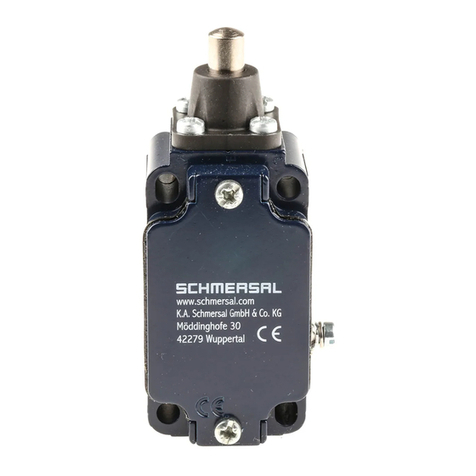
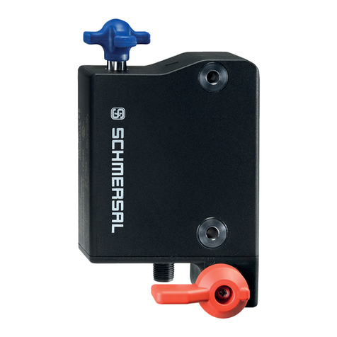
manuals.online logo
Brands
  1. Home
  2. •
  3. Brands
  4. •
  5. schmersal
  6. •
  7. Switch
  8. •
  9. schmersal AZ 16zi Programming manual

schmersal AZ 16zi Programming manual

AZ 16zi
AZ 20zi
Montage- und Anschlussanleitung / Sicherheitsschalter
Mounting and wiring instructions / Safety switches
Instructions de montage et de câblage / Interrupteur de sécurité
Bestimmung und Gebrauch
Die Sicherheitsschalter AZ 16zi und AZ 20zi entsprechen der Kate-
gorie 2 der Prüfgrundsätze für zwangsöffnende Positionsschalter für
Sicherheitsfunktion BG-GS-ET 15 der deutschen Berufsgenossen-
schaften. Sie werden an Schutzgittern, Hauben und Türen verwen-
det, die geschlossen sein müssen, um die erforderliche Betriebs-
sicherheit zu gewährleisten. Erweiternd kann der AZ 20zi für be-
schleunigte Betätigungen (bis max. 40 m/s2) eingesetzt werden.
Hinweis
Der elektrische Anschluss darf nur von autorisiertem Fachpersonal
durchgeführt werden.
Die Konformitätserklärung nach Maschinen- und Niederspannungs-
richtlinie senden wir Ihnen auf Wunsch gerne zu oder kann im
Internet abgerufen werden. Weitere technische Informationen ent-
nehmen Sie bitte dem Schmersal Gesamtkatalog.
Destination and use
The safety switches AZ 16zi and AZ 20zi conform to category 2 of
the testing regulations for positive break position switches with
safety function according to BG-GS-ET-15 of the German Berufs-
genossenschaften (relevant authorities). They are designed for hin-
ged and swivelling protective covers, flaps and doors, to ensure the
required operation safety. Additionally the AZ 20zi can be used for
accelerated actauation (max. 40 m/s2).
deutsch
Destination et usage
Les interrupteurs de sécurité AZ 16zi et AZ 20zi correspondent à la
catégorie 2 des principes d'essai pour des interrupteurs de position
à ouverture forcée pour fonctions de sécurité BG-GS-ET 15 des
caisses allemandes de prévoyance des accidents (Berufsgenossen-
schaften). Ils se montent sur des grilles de protection, des capots et
des protecteurs pivotants qui doivent être fermés pour garantir la
sécurité de fonctionnement requise. Par extension, le modèle
AZ 20zi peut être utilisé pour des manœuvres accélérées (jusqu'à
40 m/s2 environ).
Remarque
Le raccordement électrique doit être effectué uniquement par du
personnel technique habilité. Une attestation de conformité à la
directive Machines et Basse Tension peut vous être adressée sur
simple demande ou obtenue via Internet.
english
français
Abmessungen
Dimensions
Dimensions
Betätigungsöffnungen
Actuator openings
Orifices d’actionneur
AZ 16zi: A-D
AZ 20zi: A, C
14
Pg 11 / M16 x 1,5
52
5,5
28
15,5 718 8
29
90
40
A
BC
D
8
13
9
30
Notice
The electrical connection may only be carried out by an authorized
person.
The declaration of conformity according to the Machinery and Low
Voltage Directive can be mailed to you on request or can be drawn
from our webside. Further technical information can be found in the
Schmersal Main Catalogue.
AZ 16zi
AZ 20zi
Montage- und Anschlussanleitung / Sicherheitsschalter
Mounting and wiring instructions / Safety switches
Instructions de montage et de câblage / Interrupteur de sécurité
deutsch
english
français
Befestigung/Anschluss
Bei der Montage ist darauf zu achten, dass ein Verschieben des
Schalters in Betätigungsrichtung auch im Fehlerfall verhindert wird.
Den individuell codierten Betätiger seitenrichtig montieren, siehe
Kontur des Betätigers auf dem Schaltergehäuse. Den Betätiger
formschlüssig direkt mit der Schutzeinrichtung verbinden. Verwen-
den Sie als Sicherung gegen unbefugtes Lösen die beigefügten
Senkschrauben mit Einwegschlitz. Bei Befestigung, z. B. durch
Nieten oder Schweißen, ist darauf zu achten, dass sich die Ein-
tauchtiefe des Betätigers nicht ändert. Das Schaltergehäuse darf
nicht als Anschlag benutzt werden. Die Gebrauchslage ist beliebig.
Sie sollte jedoch so gewählt werden, dass kein grober Schmutz in
die benutzte Öffnung eindringen kann. Die nicht benutzten Öffnun-
gen sind nach der Montage mit den beiliegenden Schlitzverschluss-
folien zu verschließen. Die Einstellung der Kugelrastung (-2053) ist
nach erfolgter Montage an der Schutzeinrichtung vorzunehmen.
Hierzu mittels Schraubendreher die Schrauben der Kugelrastung
gleichmäßig einstellen. Bitte beachten Sie auch die Hinweise oder
Normen EN 292, EN 953 und EN 1088.
Fixation/Raccordement
Lors du montage, veiller à empêcher tout décalage de l'interrupteur
dans la direction d'actionnement même en cas de défaut. Monter
les actionneurs codés individuellement sur le côté adéquat, se
reporter au profil d'actionneur figurant sur le boîtier de l'interrupteur.
Relier l'actionneur directement au protecteur selon un engagement
positif. Pour éviter tout démontage intempestif, utiliser les vis à tête
fraisée avec fente de vissage unidirectionnelle fournies. En cas de
fixation selon un mode différent, par exemple par rivetage ou sou-
dage, veiller à ce que la profondeur de plongée de l'actionneur ne
varie pas. Ne pas utiliser le boîtier de l'interrupteur comme butée. La
position d'utilisation est indifférente. Toutefois, elle doit être choisie
de manière à empêcher la pénétration de salissures grossières dans
l'orifice utilisé. Les orifices non utilisés doivent être obturés après
montage à l'aide des adhésifs obturateurs fournis. Le réglage du
loqueteau à bille (–2053) se fait après le montage sur le protecteur.
Pour ce faire, régler uniformément les vis du loqueteau à bille à l'ai-
de d'un tournevis. Respecter également les directives ou normes
EN 292, EN 953 et EN 1088.
or riveting of the actuator, that the insertion depth of the actuator
is not altered. The switch may not be used as an endstop! The
switch is suitable for any mounting position. It should be selected in
such a way that no coarse dirt can fall into the used slot. The unu-
sed slots should be protected with the self-adhesive foil. The adjust-
ment of the ball catch (-2053) should be done after mounting of the
safety switch. Please adjust screws at both sides with the same
number of turns with a screwdriver. Please observe the instructions
in the standards EN 292, EN 953 and EN 1088.
Mounting/connection
Please ensure that, even in case of failure, the safety switch can not
be moved from its position. The individually coded actuator has to
be mounted facing the correct way, see outlining of actuator on
housing of the switch. The actuator must be securely mounted to a
stable position of the safety device, i.e. not on weak supports which
could flex during operation. Please ensure this is fitted the correct
way round, and tighten the actuator with attached the one-way
screws, to prevent deliberate removal. Please ensure with welding
Dargestellt: Schließerkontakt (Ausführung AZ 16/20ziG24)
LED grün GN: Betriebsspannungsanzeige
LED gelb YE: Schaltzustandsanzeige
Beide für 24 VDC Betriebsspannung.
Die Schaltzustandsanzeige darf nicht an den Sicherheitskontakt
angeschlossen werden!
Geschützt gegen Verpolung und Spannungsspitzen.
Shown: NO contact (type AZ 16/20ziG24)
LED green GN: indicator for supply voltage
LED yellow YE: indicator for switch operation
Both for 24 VDC supply voltage.
The yellow LED may not be connected to the safety circuit!
Protection against wrong polarity and voltage peaks.
Représenté avec contact NO (version AZ 16/20ziG24)
LED verte (GN): indicateur de présence tension
LED jaune (YE): indicateur d'état de commutation
Chaques pour 24 V.c.c. présence tension.
L'indicateur d'état de commutation (LED jaune) ne doit pas
être relié au contact de sécurité.
Protégé contre les inversions de polarité et les surtensions.
LED-Ausführungen
LED version
Version à LED
13 14
15
YE GN
13
14
15
24 VDC
L-
L+
GNYE
AZ 16zi
AZ 20zi
Montage- und Anschlussanleitung / Sicherheitsschalter
Mounting and wiring instructions / Safety switches
Instructions de montage et de câblage / Interrupteur de sécurité
Verdrahtung und Abdichtung
Zur Leitungseinführung sind geeignete Kabelverschraubungen mit
entsprechender Schutzart zu verwenden. Es stehen hierfür drei
Leitungseinführungen Pg 11 bzw. M16 x 1,5 zur Verfügung, die
nach Bedarf ausgebrochen werden können. Nach erfolgtem An-
schluss ist der Schalterinnenraum von Schmutzteilen zu säubern
(ausgebrochene Wände der Pg-Verschraubung, Kabelreste etc.).
Der Sicherheitsschalter ist schutzisoliert. Ein Schutzleiter ist des-
halb nicht zulässig.
Wartung
Bei sorgfältiger Montage unter Beachtung der oben beschriebenen
Hinweise ist nur eine geringe Wartung notwendig. Bei rauen Be-
triebsbedingungen empfehlen wir eine regelmäßige Wartung mit
folgenden Schritten:
1. Prüfen des Betätigers und des Sicherheitsschalters auf festen Sitz
2. Entfernen von Schmutz
3. Prüfen der Leitungseinführung und -anschlüsse
Wiring and Sealing
For cable entries please use suitable cable glands with the same IP
rating. There are three Pg 11 or M16 x 1,5 entries, which can be
broken out for use. Please clean the inside of the switch from dirt
after wiring (broken off parts of the PG entries and wire pieces etc).
The safety switch is double insulated. A protective lead must not
be connected.
Maintenance
With careful mounting as described above, the switch requires little
maintenance. With rough conditions, we recommend quarterly
maintenance per the following steps:
1. Check for tight installation of the actuator and switch
2. Remove all debris or particles
3. Check the sealing of the cable and the conduit connections
deutsch Câblage et étanchéité
Pour les passages de filerie, utiliser des presse-étoupe appropriés
avec le degré de protection correspondant. Trois passages de
câbles Pg 11 ou M16 x 1,5 à défoncer à la demande sont prévus à
cet effet. Une fois le câblage terminé, nettoyer impérativement
l'intérieur de l'interrupteur pour éliminer les débris (morceaux de
parois de presse-étoupe, résidus de fils, etc.). L'interrupteur de
sécurité est à double isolement. Par conséquent, un conducteur
de protection n'est pas admis.
Entretien
L'entretien requis est minime lorsque le montage est effectué
avec soin en respectant les consignes ci-dessus. En cas de
fonctionnement dans un environnement difficile, il est recommandé
d'effectuer un entretien régulier qui consiste à:
1. Contrôler que l'actionneur et l'interrupteur de sécurité sont
solidement fixés.
2. Eliminer les salissures.
3. Contrôler les entrées de filerie et les raccordements.
english
français
Kontakte
Contacts
Contacts
21
13 22
14
AZ 16zi
AZ 20-11zi
11
21
33
12
22
34
AZ 16-12zi
21
11 22
12
AZ 16-02zi
AZ 20-02zi
11
21
31
12
22
32
AZ 16-03zi
1 Schließer / 1 Öffner
1 NO / 1 NC contact
1 NO / 1 NF contact
1 Schließer / 2 Öffner
1 NO / 2 NC contact
1 NO / 2 NF contacts
2 Öffner
2 NC contacts
2 NF contacts
3 Öffner
3 NC contacts
3 NF contacts
AZ 16zi
AZ 20zi
Montage- und Anschlussanleitung / Sicherheitsschalter
Mounting and wiring instructions / Safety switches
Instructions de montage et de câblage / Interrupteur de sécurité
Hinweis
Die Betätiger sind nicht einzeln lieferbar.
Notice
The actuators are not available separately.
Remarque
Les actionneurs ne peuvent pas être obtenus séparément.
deutsch
english
français
5
34,7
56
40
16
23 2
¤5,5
40
28
17,5
1,5
814 10,5
gerade Bauform mit Haftmagnet
straight type with magnetic latch
Forme droite avec loqueteau magnétique
B1-1747
gerade Bauform
straight type
Forme droite
B1
23
ø5,5
56
10
20,5
28,5
40
5
34,6
52
40
16
814 6
gerade Bauform mit Schlitzabdeckung
straight type with slot cover
Forme droite avec obturateur
B1-2024
23
ø5,5
58
10
25
40
11
5
40,6
AZ 16zi
AZ 20zi
Montage- und Anschlussanleitung / Sicherheitsschalter
Mounting and wiring instructions / Safety switches
Instructions de montage et de câblage / Interrupteur de sécurité
52
31,4
28
16
10,9
814 6
gerade Bauform mit Zentrierhilfe
straight type with centering facility
Forme droite avec centreur
B1-2177
23
5,5
5
11
10
40
56
40,7
23
ø5,5
56
10
20,5
28,5
40
5
34,6
gerade Bauform mit Kugelrastung
straight type with with ball catch
Forme droite avec loqueteau à bille
B1-2053
48
40
14,7
814 14
AZ 16zi
AZ 20zi
Montage- und Anschlussanleitung / Sicherheitsschalter
Mounting and wiring instructions / Safety switches
Instructions de montage et de câblage / Interrupteur de sécurité
Caractéristiques techniques
Normes de référence: CEI/EN 60947-5-1; EN 1088 BG-GS-ET-15
Boîtier: thermoplastique chargé de fibres de verre, auto-extinguible
Actionneur: acier inoxydable 1.4301
Vitesse d'actionnement: AZ 16zi: maxi 2 m/s
Etanchéité: IP 67 suivant CEI/EN 60529
Matériau des contacts: argent
Elément de commutation: inverseur à double rupture, contacts isolés galvaniquement
Type de commutation: ACEI 60947-5-1; BBG-GS-ET-15 rupture lente, contact NF à ouverture forcée
Type de raccordemen : raccordement; section de fil maxi 2,5 mm2(avec embouts)
Tension de tenue assignée aux chocs Uimp: 6 kV
Tension assignée d'isolement Ui: 500 V
Catégorie d'utilisation: AC-15; DC-13
Pouvoir de coupure nominal Ie/Ue: 4 A/230 V c.a.; 4 A/24 V c.c.
Tenue aux courts circuits: 6 A gL/gG D-fusible
Force de maintien: environ 30 N pour AZ 16/20zi-1747; jusqu'à environ 100 N avec AZ 1620zi-2053
Course d'ouverture forcée: 8 mm
Force d'ouverture forcée: 10 N à chaque contact NF
Température ambiante: – 30 °C … + 80 °C
Durée de vie mécanique: > 106manœuvres
Accessoire: affichage à LED 24 V c.c.
Homologué pour ascenseurs: CSA B 44.1 / ASME A 17.5 D
Actionnement accéléré: AZ 20zi: maxi 40 m/s2(à 10 x 103manœuvres)
deutsch
english
français
K.A.Schmersal GmbH&Co.
Industrieschaltgeräte
Möddinghofe 30
D-42279 Wuppertal
Telefon +49 - (0)2 02 - 64 74-0
Telefax +49 - (0)2 02 - 64 74 - 1 00
E-Mail: [email protected]
Internet: http://www.schmersal.de
5.000/v.A./07.00/Ident-Nr. 5042706000/ BZ-Nr. 50106-29.00 /Ausgabe I
Technische Daten
Vorschriften: IEC/EN 60947-5-1/DIN VDE 0660-200; EN 1088 BG-GS-ET-15
Gehäuse: Glasfaserverstärkter Thermoplast, selbstverlöschend
Betätiger: Nichtrostender Stahl 1.4301
Betätigungsgeschwindigkeit: AZ 16zi: max. 2 m/s
Schutzart: IP 67 nach IEC/EN 60529 DIN VDE 0470-1
Kontaktmaterial: Silber
Schaltglied: Wechsler mit Doppelunterbrechung, galvanisch voneinander getrennte Kontaktbrücken
Schaltsystem: Agem. IEC 60947-5-1; Bgem. BG-GS-ET-15 Schleichschaltung, zwangsöffnender Öffner
Anschlussart: Schraubanschluss; Anschlussquerschnitt max. 2,5 mm2(einschl. Aderendhülse)
Bemessungsstoßspannungsfestigkeit Uimp: 6 kV
Bemessungsisolationsspannung Ui: 500 V
Gebrauchskategorie: AC-15; DC-13
Bemessungsbetriebsstrom/-spannung Ie/Ue: 4 A/230 VAC; 4 A/24 VDC
Kurzschlussfestigkeit: 6 A gL/gG D-Sicherung
Haftkraft: ca. 30 N bei AZ 16/20zi-1747; bis ca. 100 N bei AZ 16/20zi-2053
Zwangsöffnungsweg: 8 mm
Zwangsöffnungskraft: 10 N je Öffnerkontakt
Umgebungstemperatur: – 30 °C … + 80 °C
Mechanische Lebensdauer: > 106Schaltspiele
Zubehör: LED-Anzeige 24 VDC
Zugelassen für Aufzugsbau: CSA B 44.1 / ASME A 17.5 D
Beschleunigte Betätigung: AZ 20zi: max. 40 m/s2(bei 10 x 103Schaltspielen)
Technical Data
Standards: IEC/EN 60947-5-1; BG-GS-ET 15; EN 1088
Body and actuator flange: Fibreglass reinforced thermoplastic, self-extinguishing
Actuator: Stainless steel 1.4301
Actuating spead: AZ 16zi: max. 2 m/s
Degree of protection: IP 67 per IEC/EN 60529
Contacts: Silver
Switching element: Double pole, double break, electrically separated contact bridges
switching system: Aper IEC 60947-5-1;. Bper BG-GS-ET-15 slow action, positive break, NC contact
Type of terminals: M 3.5 screws, self-lifting clamps, max. 2.5 mm2(AWG 13 / wire incl. conductor ferrules)
Rated impulse withstandvoltage Uimp: 6 kV
Rated isolation voltage Ui: 500 V
Utilization category: AC-15; DC-13
Rated operational current/-voltage Ie/Ue: 4 A/230 VAC; 4 A/24 VDC
Short-circuit protection: 6 A gL/gG D-fuse
Closing force (max): approx. 30 N for AZ 16/20zi-1747; approx. 100 N for AZ 16/20zi-2053
Travel positive break: 8 mm
Force for positive break: 10 N per NC contact
Ambient temperature: – 30 °C … + 80 °C
Mechanical life: > 106operations
Accessories: LED indication 24 VDC
Approved for elevator use: CSA B 44.1 / ASME A 17.5 D
UL/CSA: same polarity; type four enclosure
Accelerated actuation: AZ 20zi: max. 40 m/s2(at 10 x 103operations)

This manual suits for next models

6

Other schmersal Switch manuals

schmersal EX-TV.S 335 User manual

schmersal

schmersal EX-TV.S 335 User manual

schmersal BN 325-R User manual

schmersal

schmersal BN 325-R User manual

schmersal AZM300Z-ST-SD2P-T-DU User manual

schmersal

schmersal AZM300Z-ST-SD2P-T-DU User manual

schmersal AZM300B-I2-ST-SD2P-DU Operation and maintenance manual

schmersal

schmersal AZM300B-I2-ST-SD2P-DU Operation and maintenance manual

schmersal AZ 415-33ZPK User manual

schmersal

schmersal AZ 415-33ZPK User manual

schmersal TFH 232 AS User manual

schmersal

schmersal TFH 232 AS User manual

schmersal AZM300B-ST-1P2P-DU User manual

schmersal

schmersal AZM300B-ST-1P2P-DU User manual

schmersal TQ 700 S User manual

schmersal

schmersal TQ 700 S User manual

schmersal TESF series User manual

schmersal

schmersal TESF series User manual

schmersal AZM300Z-I2-STSD2P User manual

schmersal

schmersal AZM300Z-I2-STSD2P User manual

schmersal AZ 15 ZO User manual

schmersal

schmersal AZ 15 ZO User manual

schmersal TQ 700 Instruction manual

schmersal

schmersal TQ 700 Instruction manual

schmersal TFH 232-11UEDR User manual

schmersal

schmersal TFH 232-11UEDR User manual

schmersal Z/T 235 AS User manual

schmersal

schmersal Z/T 235 AS User manual

schmersal MAF/S 441-11Y User manual

schmersal

schmersal MAF/S 441-11Y User manual

schmersal EX-T3Z 068 User manual

schmersal

schmersal EX-T3Z 068 User manual

schmersal AZM300B-I2-ST-SD2P User manual

schmersal

schmersal AZM300B-I2-ST-SD2P User manual

schmersal ZSD1 User manual

schmersal

schmersal ZSD1 User manual

schmersal TQ200 User manual

schmersal

schmersal TQ200 User manual

schmersal PS116 series User manual

schmersal

schmersal PS116 series User manual

schmersal EX-ZQ 900 User manual

schmersal

schmersal EX-ZQ 900 User manual

schmersal BNS-B20 User manual

schmersal

schmersal BNS-B20 User manual

schmersal AZM 200 D User manual

schmersal

schmersal AZM 200 D User manual

schmersal AZM300Z-ST-1P2P-DU Operation and maintenance manual

schmersal

schmersal AZM300Z-ST-1P2P-DU Operation and maintenance manual

Popular Switch manuals by other brands

ADTRAN NetVanta 1561i-04 quick start

ADTRAN

ADTRAN NetVanta 1561i-04 quick start

ATEN Master View CS-1754 user manual

ATEN

ATEN Master View CS-1754 user manual

KROHNE ARV52 Handbook

KROHNE

KROHNE ARV52 Handbook

Allen-Bradley Stratix 5200 1783-CMS6B installation instructions

Allen-Bradley

Allen-Bradley Stratix 5200 1783-CMS6B installation instructions

ANTAIRA LMX-0702G-SFP-V2 Series Quick installation guide

ANTAIRA

ANTAIRA LMX-0702G-SFP-V2 Series Quick installation guide

STE VS8 user manual

STE

STE VS8 user manual

Pickering 40/42-87 A Series user manual

Pickering

Pickering 40/42-87 A Series user manual

CalDigit Element Hub user guide

CalDigit

CalDigit Element Hub user guide

Micrel KSZ8862-16MQL manual

Micrel

Micrel KSZ8862-16MQL manual

Lantech IPES-5416T Series user manual

Lantech

Lantech IPES-5416T Series user manual

Surecom EP-824DX-FS user manual

Surecom

Surecom EP-824DX-FS user manual

SICK T4000 Standard operating instructions

SICK

SICK T4000 Standard operating instructions

Sennheiser UI 815 quick guide

Sennheiser

Sennheiser UI 815 quick guide

Avocent DSR SWITCH - Installer/user guide

Avocent

Avocent DSR SWITCH - Installer/user guide

Cisco WS-C2948G-GE-TX Configuration guide

Cisco

Cisco WS-C2948G-GE-TX Configuration guide

Hall Research Technologies MC1208 user manual

Hall Research Technologies

Hall Research Technologies MC1208 user manual

ETIC XSLAN+ Series user guide

ETIC

ETIC XSLAN+ Series user guide

Galletti FLAT CB manual

Galletti

Galletti FLAT CB manual

manuals.online logo
manuals.online logoBrands
  • About & Mission
  • Contact us
  • Privacy Policy
  • Terms and Conditions

Copyright 2025 Manuals.Online. All Rights Reserved.