SICK T4000 Standard User manual

OPERATING INSTRUCTIONS
T4000 Standard
Transponder safety switches

Described product
T4000 Standard
Transponder safety switches
Manufacturer
SICK AG
Erwin-Sick-Str. 1
79183 Waldkirch
Germany
Legal information
This work is protected by copyright. Any rights derived from the copyright shall be
reserved for SICK AG. Reproduction of this document or parts of this document is only
permissible within the limits of the legal determination of Copyright Law. Any modifica‐
tion, abridgment or translation of this document is prohibited without the express writ‐
ten permission of SICK AG.
The trademarks stated in this document are the property of their respective owner.
© SICK AG. All rights reserved.
Original document
This document is an original document of SICK AG.
2O P E R A T I N G I N S T R U C T I O N S | T4000 Standard 8022720/2019-05-08 | SICK
Subject to change without notice

Contents
1 About this document........................................................................ 5
1.1 Function of this document....................................................................... 5
1.2 Scope......................................................................................................... 5
1.3 Target groups and structure of these operating instructions................ 5
1.4 Further information................................................................................... 5
1.5 Symbols and document conventions...................................................... 6
2 Safety information............................................................................ 8
2.1 General safety notes................................................................................ 8
2.2 Intended use............................................................................................. 8
2.3 Requirements for the qualification of personnel.................................... 8
3 Product description........................................................................... 10
3.1 Structure and function............................................................................. 10
3.2 Product characteristics............................................................................ 11
4 Project planning................................................................................ 12
4.1 Manufacturer of the machine.................................................................. 12
4.2 Operating entity of the machine.............................................................. 12
4.3 Design........................................................................................................ 12
4.4 Integration into the electrical control...................................................... 13
4.5 Thorough check concept.......................................................................... 13
5 Mounting............................................................................................. 15
5.1 Safety......................................................................................................... 15
5.2 Unpacking.................................................................................................. 15
5.3 Mounting................................................................................................... 15
6 Electrical installation........................................................................ 18
6.1 Safety......................................................................................................... 18
6.2 Notes on cULus......................................................................................... 18
6.3 Sensor connection.................................................................................... 18
6.4 Evaluation unit connection....................................................................... 19
6.5 Block diagram........................................................................................... 21
7 Commissioning.................................................................................. 22
7.1 Safety......................................................................................................... 22
7.2 Switching on.............................................................................................. 22
7.3 Teach-in..................................................................................................... 22
7.4 Thorough check........................................................................................ 23
8 Troubleshooting................................................................................. 24
8.1 Safety......................................................................................................... 24
8.2 LED status indicators............................................................................... 24
8.3 System status........................................................................................... 25
CONTENTS
8022720/2019-05-08 | SICK O P E R A T I N G I N S T R U C T I O N S | T4000 Standard 3
Subject to change without notice

9 Maintenance...................................................................................... 26
9.1 Safety......................................................................................................... 26
9.2 Cleaning..................................................................................................... 26
9.3 Regular thorough check........................................................................... 26
9.4 Thorough check of the safety function.................................................... 26
9.5 Functional test (self-test).......................................................................... 27
10 Decommissioning............................................................................. 28
10.1 Disposal..................................................................................................... 28
11 Technical data.................................................................................... 29
11.1 Evaluation unit T4000-1RBA01............................................................... 29
11.2 Sensors T4000-DNA................................................................................. 31
11.3 T4000-1KBA actuator.............................................................................. 32
11.4 Dimensional drawings.............................................................................. 32
12 Ordering information........................................................................ 34
12.1 Devices...................................................................................................... 34
12.2 Accessories............................................................................................... 34
13 Annex.................................................................................................. 35
13.1 Compliance with EU directives................................................................. 35
14 List of figures..................................................................................... 36
15 List of tables....................................................................................... 37
CONTENTS
4O P E R A T I N G I N S T R U C T I O N S | T4000 Standard 8022720/2019-05-08 | SICK
Subject to change without notice

1 About this document
1.1 Function of this document
These operating instructions contain the information needed during the life cycle of the
safety switch.
They must be made available to all people who work with the safety switch.
1.2 Scope
These operating instructions apply only to the T4000 Standard transponder safety
switches as from the date of manufacture:
•1007xxxx
You will find the date of manufacture of the device in the field Date Code on the type
label in the format yywwxxxx (yy = year, ww = calendar week, xxxx = serial number).
1.3 Target groups and structure of these operating instructions
These operating instructions are intended for the following target groups: project devel‐
opers (planners, developers, designers), installers, electricians, safety experts (such as
CE authorized representatives, compliance officers, people who test and approve the
application), operators, and maintenance personnel.
The structure of these operating instructions is based on the life cycle phases of the
safety switch: project planning, mounting, electrical installation, commissioning, opera‐
tion, and maintenance.
In many applications, the target groups consist of the manufacturer and the operating
entity of the machine in which the safety switch is integrated:
Area of responsibility Target group Specific chapters of these operating instruc‐
tions 1)
Manufacturer Project developers
(planners, developers,
designers)
Project planning, page 12
Technical data, page 29
Accessories, page 34
Installers Mounting, page 15
Electricians Electrical installation, page 18
Safety experts Project planning, page 12
Commissioning, page 22
Technical data, page 29
Operating entity Operators Troubleshooting, page 24
Maintenance person‐
nel
Maintenance, page 26
Troubleshooting, page 24
Ordering information, page 34
1) Chapters not listed here are intended for all target groups. All target groups must follow all of the safety
and warning instructions in all chapters of the operating instructions!
In other applications, the operating organization is also the manufacturer of the equip‐
ment with the corresponding allocation of the target groups.
1.4 Further information
www.sick.com
The following information is available via the Internet:
ABOUT THIS DOCUMENT 1
8022720/2019-05-08 | SICK O P E R A T I N G I N S T R U C T I O N S | T4000 Standard 5
Subject to change without notice

•This document in other languages
•CAD data for drawings and dimensional drawings
•Certificates (such as the EU declaration of conformity)
•Guide for Safe Machinery Six steps to a safe machine
1.5 Symbols and document conventions
The following symbols and conventions are used in this document:
Safety notes and other notes
DANGER
Indicates a situation presenting imminent danger, which will lead to death or serious
injuries if not prevented.
WARNING
Indicates a situation presenting possible danger, which may lead to death or serious
injuries if not prevented.
CAUTION
Indicates a situation presenting possible danger, which may lead to moderate or minor
injuries if not prevented.
NOTICE
Indicates a situation presenting possible danger, which may lead to property damage if
not prevented.
NOTE
Indicates useful tips and recommendations.
Instructions to action
bThe arrow denotes instructions to action.
1. The sequence of instructions for action is numbered.
2. Follow the order in which the numbered instructions are given.
✓The check mark denotes the result of an instruction.
LED symbols
These symbols indicate the status of an LED:
oThe LED is off.
ÖThe LED is flashing.
OThe LED is illuminated continuously.
Terminology
Dangerous state
A dangerous state is a status of the machine or facility, where people may be injured.
Protective devices prevent this risk if the machine is operated within its intended use.
The figures in this document always show the dangerous state of the machine as move‐
ment of a machine part. In practice, there are different dangerous states, such as:
•Machine movements
•Electrical parts
1 ABOUT THIS DOCUMENT
6O P E R A T I N G I N S T R U C T I O N S | T4000 Standard 8022720/2019-05-08 | SICK
Subject to change without notice

•Visible and invisible beam
•A combination of multiple hazards
ABOUT THIS DOCUMENT 1
8022720/2019-05-08 | SICK O P E R A T I N G I N S T R U C T I O N S | T4000 Standard 7
Subject to change without notice

2 Safety information
2.1 General safety notes
This chapter contains general safety information about the safety switch.
Further information about specific product use situations can be found in the relevant
chapters.
DANGER
Hazard due to lack of effectiveness of the protective device
In the case of non-compliance, it is possible that the dangerous state of the machine
may not be stopped or not stopped in a timely manner.
bPlease read this document carefully and make sure that you understand the con‐
tent fully before working with the device.
bFollow all safety notes in this document.
2.2 Intended use
NOTICE
The user is responsible for ensuring that the device is correctly incorporated into a safe
overall system. This involves validating the overall system according to specifications
such as those defined in ISO 13849-2 or EN 62061.
The T4000 Standard transponder safety switch is switched by a non-contact actuator
and is suitable for the following applications:
■Movable physical guards
■Safe position monitoring
The safety switch must be used only on the machine on which it was planned, mounted,
installed and initially commissioned by qualified safety personnel in accordance with
these operating instructions.
Incorrect use, improper modification or manipulation of the safety switch will invalidate
any warranty from SICK; in addition, any responsibility and liability of SICK for damage
and secondary damage caused by this is excluded.
The safety switch is not suitable for the ambient conditions such as, but not limited, to
the following:
•Radioactivity (exception: natural radioactivity)
•Vacuum or high pressure
•High UV load
•In the vicinity of low-frequency RFID devices
•In the vicinity of magnetic fields
The following may impair the function of the safety switch:
•Metal subsurface or metal in direct proximity
•Passing metal chips
2.3 Requirements for the qualification of personnel
The safety switch must be configured, mounted, connected, commissioned, and ser‐
viced by qualified safety personnel only.
2 SAFETY INFORMATION
8O P E R A T I N G I N S T R U C T I O N S | T4000 Standard 8022720/2019-05-08 | SICK
Subject to change without notice

Project planning
For project planning, a person is considered competent when he/she has expertise and
experience in the selection and use of protective devices on machines and is familiar
with the relevant technical rules and national work safety regulations.
Mechanical mounting, electrical installation, and commissioning
For the task, a person is considered qualified when he/she has the expertise and expe‐
rience in the relevant field and is sufficiently familiar with the application of the protec‐
tive device on the machine to be able to assess whether it is in an operationally safe
state.
Operation and maintenance
For operation and maintenance, a person is considered competent when he/she has
the expertise and experience in the relevant field and is sufficiently familiar with the
application of the protective device on the machine and has been instructed by the
machine operator in its operation.
SAFETY INFORMATION 2
8022720/2019-05-08 | SICK O P E R A T I N G I N S T R U C T I O N S | T4000 Standard 9
Subject to change without notice

3 Product description
3.1 Structure and function
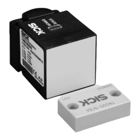
Figure 1: Components of the T4000 Standard transponder safety switch
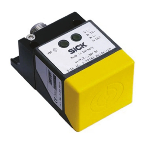
1Sensor
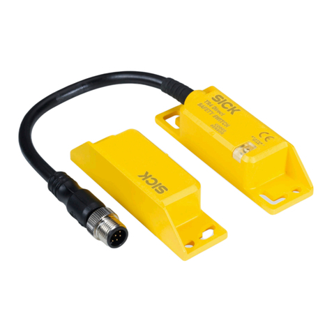
2Actuator (transponder)
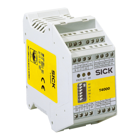
3Evaluation unit
The T4000 Standard transponder safety switch consists of three components:
•Sensor
The sensor is mounted on the fixed part of the guard and is connected to the eval‐
uation unit.
•Actuator (transponder)
The actuator is mounted on the movable part of the guard.
Each actuator has a unique electronic code.
•Evaluation unit
The evaluation unit must be installed in a control cabinet with an enclosure rating
of at least IP54.
3 PRODUCT DESCRIPTION
10 O P E R A T I N G I N S T R U C T I O N S | T4000 Standard 8022720/2019-05-08 | SICK
Subject to change without notice

Operating principle
The T4000 Standard transponder safety switch monitors movable physical guards:
■Operation of the machine in automatic mode is possible only if the guard is closed.
■A stop command is triggered if the guard is opened while the machine is running.
The T4000 Standard transponder safety switch is uniquely coded: An actuator must be
taught in at the sensor during commissioning. It is possible to teach in up to 8 actua‐
tors in succession. Only the most recently taught-in actuator is valid.
When the guard is closed, the actuator is moved towards the sensor. The sensor
detects the code of the actuator when it reaches the switch-on distance. If the sensor
detects a taught-in code (valid actuator), the system sets the safety outputs (relay out‐
puts) and the application diagnostic output OUT to HIGH.
When the guard is opened, the actuator is moved out of the sensor’s response range.
The system sets the safety outputs and the application diagnostic output OUT to LOW.
The evaluation unit enters safe status for every detectable fault due to dynamic interro‐
gation of the actuator and the redundant, diverse configuration of the safety electronics
in combination with two safety outputs. The status of the safety outputs is monitored
internally by positively guided N/C contacts (relay output).
3.2 Product characteristics
3.2.1 Product variants
The safety switch is delivered in different variants. You will find an overview of impor‐
tant distinguishing features of the variants in the following.
•Sensor with plug connector M8, 3-pin (with latching and screw connection)
•Sensor with permanently connected cable and flying leads (5, 10 or 15 m)
Complete overview of all variants: see "Ordering information", page 34.
3.2.2 Sensing face
The sensor has a sensing face, see "Dimensional drawings", page 32.
3.2.3 Fault detection
Any faults that occur, including internal device faults, are detected at the latest with the
next request to close the safe contacts (e.g. at the machine start). The safety switch
then switches to safe state. If a fault is detected, the safety circuit is switched off, the
diagnostic output ERROR is set to HIGH and the LED ERROR lights up red.
3.2.4 Status indicators
The LEDs STATE (green), OUT (yellow) and ERROR (red) indicate the operational status
of the safety switch.
Overview of the LED statuses and their meanings: see "LED status indicators",
page 24.
PRODUCT DESCRIPTION 3
8022720/2019-05-08 | SICK O P E R A T I N G I N S T R U C T I O N S | T4000 Standard 11
Subject to change without notice

4 Project planning
4.1 Manufacturer of the machine
DANGER
Failure to comply with manufacturer’s obligations
Hazard due to lack of effectiveness of the protective device
bCarry out a risk assessment before using the safety switch.
bDo not tamper with, open, or modify the components of the safety switch.
bDo not repair defective devices – they must be replaced instead.
bMake sure that switch-on commands which bring about a dangerous state of the
machine are not enabled until the protective device is closed.
bMake sure that a stop command is triggered when the protective device is opened
during the dangerous machine state.
bThe safety switches must not be defeated (contacts jumpered), rotated away,
removed, or rendered ineffective in any other way. If necessary, put measures in
place to reduce possibilities for defeat.
4.2 Operating entity of the machine
DANGER
Failure to comply with operating entity’s obligations
Hazard due to lack of effectiveness of the protective device
bModifications to the machine and modifications to the mechanical mounting of
the safety switch necessitate a new risk assessment. The results of this risk
assessment may require the operating entity of the machine to fulfill the manufac‐
turer’s obligations.
bApart from during the procedures described in this document, the components of
the safety switch must not be opened or modified.
bDo not perform repair work on the components. Improper repair of the safety
switch can lead to a loss of the protective function.
bEnsure that there is no bypassing by replacement actuators. Restrict access to
actuators.
4.3 Design
DANGER
Bypassing the protective device
Hazard due to lack of effectiveness of the protective device
1. Avoid incentives to manipulate the safety switch by means of the following mea‐
sure:
°Use permanent mounting methods for actuators (e.g. welding, adhesive
bonding, safety screws or rivets).
2. Observe the design requirements in accordance with ISO 14119 for mounting:
°Reduction of bypass possibilities of an interlocking device
°Mounting of safety switch and actuator
Mounting location
If the mounting location is not specified by the machine documentation, it must be cho‐
sen carefully, see "Mounting", page 15.
4 PROJECT PLANNING
12 O P E R A T I N G I N S T R U C T I O N S | T4000 Standard 8022720/2019-05-08 | SICK
Subject to change without notice

Distance
If several safety switches are mounted on the machine, they must be mounted at a min‐
imum distance to one another see "Mounting", page 15.
Alignment
The sensor and actuator must be mounted so that their sensing faces are directly
aligned facing each other, see "Dimensional drawings", page 32.
Actuating direction
The actuator must approach the sensing face of the sensor when the guard is closed.
4.4 Integration into the electrical control
Switch-on commands that put the machine in a dangerous state may only be activated
when the protective device is closed. When the machine goes into a dangerous state, a
stop command must be triggered if the protective device is opened. Depending on the
safety concept, the signal is analyzed by safety relays or a safety controller, for example.
The control that is connected and all devices responsible for safety must comply with
the required performance level and the required category (for example, according to
ISO 13849-1).
4.4.1 Switching behavior
•2 safety outputs (relay outputs)
•1 application diagnostic output (semiconductor output, not a safety output)
13 14
23 24
24 V O U T
13 14
23 24
24 V O U T
Safety Guard
closed open
(actuator identified) (actuator out of
operating range)
Sensor Actuator Sensor
Figure 2: Switching behavior T4000-1RBA01
4.5 Thorough check concept
The safety switch must be tested by appropriately qualified safety personnel during
commissioning, after modifications, and at regular intervals; see "Thorough check",
page 23.
Regular thorough checks serve to investigate the effectiveness of the safety switch and
discover defects resulting from modifications or external influences (such as damage or
manipulation).
PROJECT PLANNING 4
8022720/2019-05-08 | SICK O P E R A T I N G I N S T R U C T I O N S | T4000 Standard 13
Subject to change without notice
The manufacturer and operating entity must define the type and frequency of the thor‐
ough checks on the machine on the basis of the application conditions and the risk
assessment. The process of defining the thorough checks must be documented in a
traceable manner.
4.5.1 Minimum requirements for the regular thorough check
The following thorough checks must be carried out at least once a year:
•Thorough check of the protective function of the safety switch (see "Thorough
check of the safety function", page 26)
•Thorough check of secure mounting of the devices and connections
•Thorough check of the housing, cables and plug connectors for damage
•Thorough check for contamination
•Thorough check of assured switch-off distance Sar
•Thorough check of the safety switch for signs of misuse or manipulation
4 PROJECT PLANNING
14 O P E R A T I N G I N S T R U C T I O N S | T4000 Standard 8022720/2019-05-08 | SICK
Subject to change without notice
5 Mounting
5.1 Safety
DANGER
Hazard due to unexpected starting of the machine
Death or severe injury
bMake sure that the dangerous state of the machine is and remains switched off.
DANGER
Bypassing the protective device
Hazard due to lack of effectiveness of the protective device
1. Avoid incentives to manipulate the safety switch by means of the following mea‐
sure:
°Use permanent mounting methods for actuators (e.g. welding, adhesive
bonding, safety screws or rivets).
2. Observe the design requirements in accordance with ISO 14119 for mounting:
°Reduction of bypass possibilities of an interlocking device
°Mounting of safety switch and actuator
NOTICE
Incorrect mounting and unsuitable ambient conditions may damage the safety switch.
bArrange the sensor and actuator in a way that prevents damage from foreseeable
external influences.
bDo not use the sensor and actuator as a stop.
bThe holder and mounting method for the sensor and actuator must be stable
enough to ensure that correct operation can take place.
bAlways use reliable mounting elements that can only be removed using tools.
bIf misalignment results in an opening on the physical guard, this must not impair
the protection that is provided.
5.2 Unpacking
bCheck the components to ensure that all parts are complete and undamaged.
bPlease contact your respective SICK subsidiary should you have any complaints.
5.3 Mounting
Selecting the mounting location
CAUTION
Bypassing the safety switch in a simple way or unintentional actuation must be pre‐
vented by suitable installation measures in accordance with ISO 14119.
If the mounting location is not specified by the machine documentation, it must be cho‐
sen carefully.
MOUNTING 5
8022720/2019-05-08 | SICK O P E R A T I N G I N S T R U C T I O N S | T4000 Standard 15
Subject to change without notice

bSelect the mounting location so that the sensor and actuator are accessible for
maintenance work and are protected against damage.
bMount the sensor and actuator on a non-ferrous surface and at a distance from
metal parts if possible in order to avoid influencing the sensing range. If this is not
possible, the influence on the assured switch-on distance Sao and the assured
switch-off distance Sar must be checked.
bWhen the guard is closed, the sensor and actuator must be located opposite each
other in the assured switch-on distance 0.8 × Sao or closer (see "Technical data",
page 29).
NOTE
In the case of flush installation, the sensing range changes based on the installa‐
tion depth and the material of the guard.
bThe switching operation must be triggered only by the actuator specifically
intended for this.
bMake sure that all dangerous states are excluded when the guard is opened, even
if the actuator has not yet reached the assured switch-off distance Sar.
NOTE
At the assured switch-off distance Sar, the relay outputs (safety outputs) are reli‐
ably switched off even in the event of an internal component failure.
bThe sensor and actuator must not be used as a mechanical stop. If necessary, fit
an additional stop for the movable physical guard.
Mounting the sensor
bMount the sensor on the fixed part of the guard, e.g. using the supplied safety
screws.
bTightening torque: 1 Nm
Mounting the actuator
bAlign the actuator to the sensor.
bActuators must be positively connected to the guard, e.g. using the supplied safety
screws.
bIt must not be possible to remove or manipulate actuators by simple means.
bTightening torque: 1 Nm
Mounting the evaluation unit
bThe evaluation unit must be installed in a control cabinet with an enclosure rating
of at least IP54.
bA latching element on the rear of the device is used for mounting on a mounting
rail.
bIf several evaluation units are mounted next to each other in a control cabinet
without air circulation (e.g. ventilator) between the evaluation units, observe a dis‐
tance of 10 mm for heat dissipation.
5 MOUNTING
16 O P E R A T I N G I N S T R U C T I O N S | T4000 Standard 8022720/2019-05-08 | SICK
Subject to change without notice
Mounting several safety switches
bWhen several safety switches are mounted, the prescribed minimum distance Smin
of 50 mm must be adhered to in order to avoid mutual interference.
Figure 3: Minimum distance when several safety switches are mounted
MOUNTING 5
8022720/2019-05-08 | SICK O P E R A T I N G I N S T R U C T I O N S | T4000 Standard 17
Subject to change without notice
6 Electrical installation
6.1 Safety
DANGER
Hazard due to electrical voltage
Hazard due to unexpected starting of the machine
bMake sure that the machine is and remains disconnected from the power supply
during the electrical installation.
bMake sure that the dangerous state of the machine is and remains switched off
during electrical installation.
bMake sure that the outputs of the safety switch have no effect on the machine
during electrical installation.
DANGER
Incorrect safety switch connection
Loss of safety function
bWhen using insulation material or stranded connection wires, make sure they
demonstrate the required temperature resistance and mechanical load capability.
bUse only safe contacts for safety functions.
bAll electrical connections must be isolated from the mains supply either by safety
transformers (EN 61558-2-6) or equivalent isolation measures.
bUse protected cable routing to prevent the risk of cross-circuits and short-circuits.
bAll output contacts must have an adequate suppressor circuit for capacitive and
inductive loads.
bProvide external contact fuse protection for relay outputs, see "Technical data",
page 29.
6.2 Notes on cULus
For use according to the requirements of UL 508, the following conditions must be met:
■The voltage supply must correspond to Class 2 in accordance with UL 508:
°Galvanically isolated power supply unit with a maximum open-circuit voltage
of 30 V DC and a limited current of max. 8 A
°Galvanically isolated power supply unit in combination with a fuse in accor‐
dance with UL 248. This fuse should be rated for max. 3.3 A and be inte‐
grated in the 30 V DC voltage section.
■Only copper with a temperature resistance of at least 75 °C must be used as the
cable material.
6.3 Sensor connection
1. The connecting cable of the sensor must not be extended.
2. The shield of the sensor cable (strip max. 3 cm) must be connected with connec‐
tion SH of the evaluation unit.
3. The screws of the terminals must be tightened with a tightening torque of 0.6–
0.8 Nm.
6 ELECTRICAL INSTALLATION
18 O P E R A T I N G I N S T R U C T I O N S | T4000 Standard 8022720/2019-05-08 | SICK
Subject to change without notice
Sensor T4000-DNA..P (with permanently connected cable)
Figure 4: Pin assignment T4000-DNA..P
1Evaluation unit
2Sensor
3Shield
Sensor T4000-DNAC with plug connector M8, 3-pin (with latching and screw connec‐
tion)
Figure 5: Pin assignment T4000-DNAC
1Evaluation unit
2Plug connector M8 of the sensor
3Shield
6.4 Evaluation unit connection
DANGER
Improper use of the safety switch
Risk of ineffectiveness of the protective device
The dangerous state may not be stopped in the event of non-compliance.
bBoth safety outputs (relay outputs) 13/14 and 23/24 must always be evaluated in
order to guarantee safety.
bA cross-circuit between 13/14 and 23/24 can be detected only by external clock‐
ing.
bMonitoring of the series-connected contactors is necessary in order to realize cate‐
gory 3 in accordance with ISO 13849-1.
1
4
1
3
2
3
24
+ 2
4 V
D
C
0 V
white
brown
Screen terminal
Operating voltage
T 4000 Evaluation Unit
Sensor
Coded
actuator
T rans-
ponder
Figure 6: Incorrect evaluation of the safety outputs
ELECTRICAL INSTALLATION 6
8022720/2019-05-08 | SICK O P E R A T I N G I N S T R U C T I O N S | T4000 Standard 19
Subject to change without notice
1
4
13 2
3
24
+ 2
4 V
DC
0
V
T rans-
ponder
white
brown
Screen terminal
Operating voltage
T 4000 Evaluation Unit
Sensor
Coded
actuator
Figure 7: Correct evaluation of the safety outputs
DANGER
Improper use of the safety switch
Risk of ineffectiveness of the protective device
bThe application diagnostic output OUT must not be used as a safety output.
The pluggable and coded terminals on the evaluation unit allow pre-assembly of the
cable connections and thus simple and fast final assembly. They also offer maximum
safety if servicing is required.
Figure 8: Mounting using pluggable and coded terminals
bTighten the screws of the terminals with a tightening torque of 0.6–0.8 Nm.
bIf a common voltage supply is used, all inductive and capacitive loads (e.g. contac‐
tors) connected to the voltage supply must be connected with corresponding sup‐
pressors.
bThe application diagnostic outputs ERR and OUT and the terminals for sensor
H1/H2 are not short-circuit protected.
6 ELECTRICAL INSTALLATION
20 O P E R A T I N G I N S T R U C T I O N S | T4000 Standard 8022720/2019-05-08 | SICK
Subject to change without notice
This manual suits for next models
2
Table of contents
Other SICK Switch manuals
Popular Switch manuals by other brands

Siemens
Siemens RUGGEDCOM RSL910 installation guide

Roland
Roland V-800HD MKII Brochure & specs

Dell
Dell PowerEdge M1000e Specifications

Grandstream Networks
Grandstream Networks GWN7832 Quick installation guide

Linksys
Linksys EG005W - Instant Gigabit Workgroup Switch Brochure & specs

Emulex
Emulex InSpeed 350 Brochure & specs