SLM
II/ 1
D
Inhaltsverzeichnis - Teil 2
Die angegebenen Abbildungen befinden sich
am Anfang der Bedienungsanleitung.
2.1 Allgemeine Hinweise
Sicherheitshinweise beachten!
Bedienungsanleitung lesen!
Prüfungen, Einstellungen, Wartungsarbeiten
in einem Wartungsbuch dokumentieren. Bei
Fragen Bezeichnung und Art.-Nr. des Gerätes
angeben. Außerhalb von Deutschland kön-
nen andere gesetzliche oder sonstige Vor-
schriften gelten als hier beschrieben.
Die Bedienungsanleitung muss vor Anwen-
dung des Gerätes gelesen, beachtet und der
Anwender jährlich unterwiesen werden!
Achtung:
Bedienungsanleitung Teil 1
lesen und beachten!
Alle Bilder, auf die im Text mit (Bild …) ver-
wiesen wird, finden Sie in Teil 1.
Technische Änderungen vorbehalten. Abbil-
dungen können vom Original abweichen.
Verwendbare Energie: Ausschließlich gerei-
nigte, kondensatfreie und ölvernebelte
Druckluft.
Leistungsgröße Kompressor: maßgebend ist
der Luftverbrauch des Gerätes / Werkzeu-
ges.
2.2 Symbole
Achtung:
Schenken Sie diesen Symbolen höchste Aufmerksamkeit!
2.1 Allgemeine Hinweise.................. 1
2.2 Symbole.................................. 1
2.3 Sicherheitshinweise................... 2
2.4 Inbetriebnahme........................ 4
2.5 Wartung .................................. 4
2.6 Außerbetriebnahme................... 4
2.7 Ersatzteilservice ....................... 4
2.8 Gewährleistungsbedingungen ..... 4
2.9 Störungsbehebung.................... 5
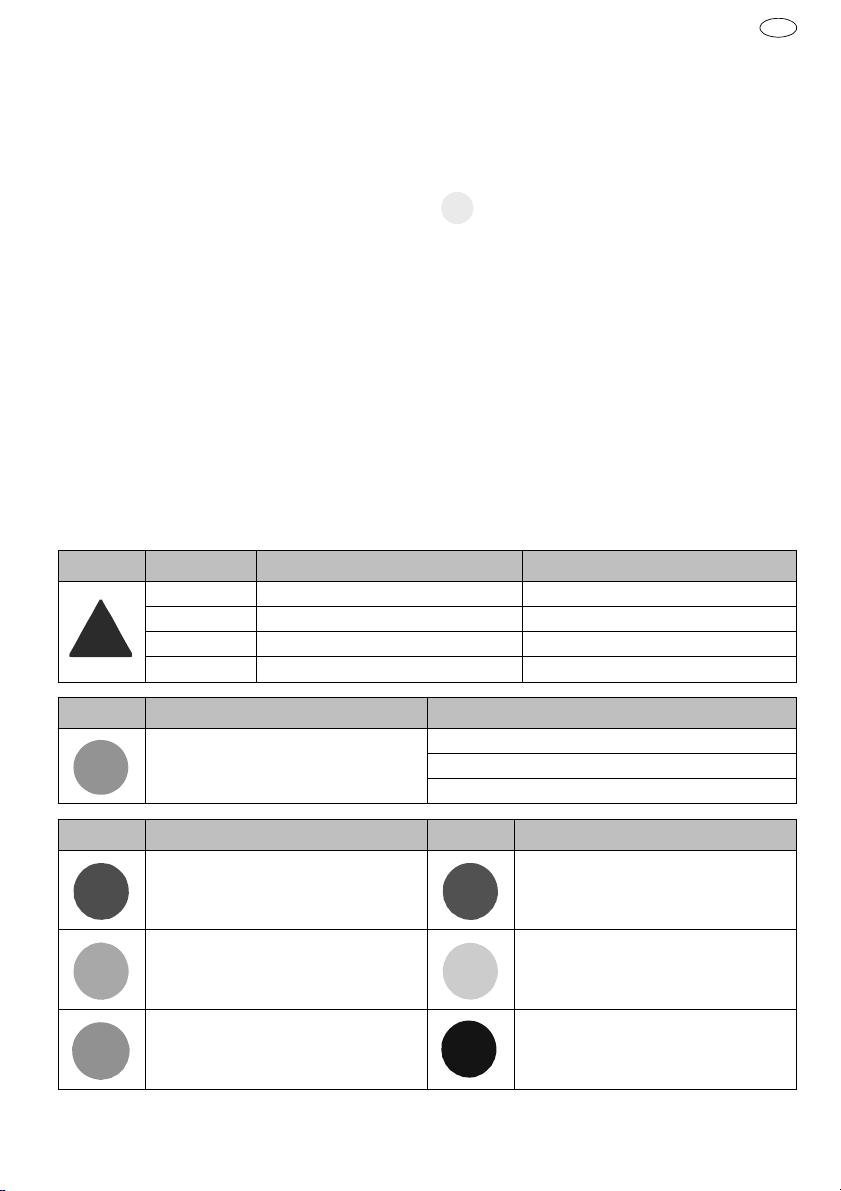
Symbol Signalwort Gefahrenstufe Folgen bei Nichtbeachtung
GEFAHR
unmittelbar drohende Gefahr Tod, schwere Körperverletzung
WARNUNG
mögliche drohende Gefahr Tod, schwere Körperverletzung
VORSICHT
mögliche gefährliche Situation Leichte Körperverletzung
HINWEIS
mögliche gefährliche Situation Sachschaden
Symbol Bedeutung Folgen bei Nichtbeachtung
Bedienungsanleitung lesen Körperverletzung oder Tod des Bedieners
Sachschaden
falsche Bedienung
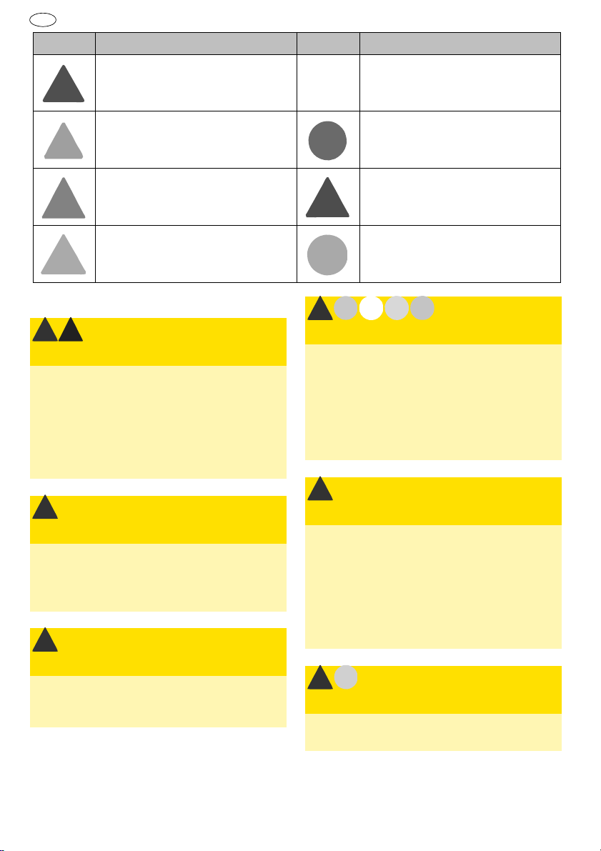
Symbol Bedeutung Symbol Bedeutung
Augenschutz tragen! Haarnetz tragen!
Gehörschutz tragen! Schutzhandschuhe tragen!
Schutzhaube tragen! Schutzkleidung tragen!