manuals.online logo
Brands
  1. Home
  2. •
  3. Brands
  4. •
  5. SCHNERZINGER
  6. •
  7. Control Unit
  8. •
  9. SCHNERZINGER COMPONENT GUARD User manual

SCHNERZINGER COMPONENT GUARD User manual

Packaging contents
COMPONENT GUARD Master
at least 1COMPONENT GUARD
module of your choice
12Vpower supply (cable length
1.5 m)
Antenna (per unit and master)
Dimensions and weight
COMPONENT GUARD MASTER:
L 7 x W 7 x H 3.5 cm / 0.3 kg
COMPONENT GUARD Module:
miscellaneous
The antennas are 11 cm long.
Dear Customer,
Thank you very much for the purchase of a
SCHNERZINGER product.
Please take sufficient time to read the
information in this guide carefully.
You will find important information on the
use of your product as well as tips for the
best possible integration into your hi-fi
system.
These instructionsmake it easier for you to
use the product,promote an
understanding of its functional properties
and help you to obtain the full
performance of the product.
We hope you enjoy using your new
SCHNERZINGER product.
COMPONENT GUARD
COMPONENT GUARD 2022-08 V1 Picture similar
COMPONENT GUARD
The COMPONENT GUARDs use the GIGA CANCELING technology to clean up internal
interference fields generated in the devices.They actively act directly in the device,in
the immediate vicinity of the signal-carrying components.
ACOMPONENT GUARD MASTER can control multiple COMPONENT GUARDs.
Step By Step Installation
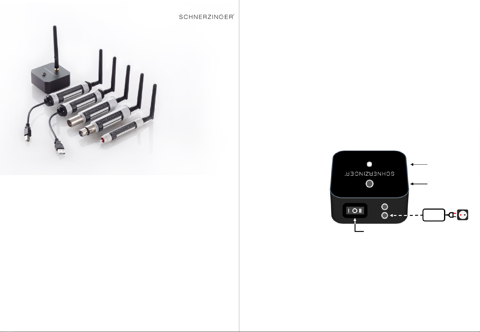
1. COMPONENT GUARD MASTER –Basic Setup
The MASTER should be placed as close as possible to the HiFi equipment, a slightly
elevated place has also proven to be successful.
In the basic setting,it is operated without the 12Vpower supply.
Connect the antenna
(vertical position).
Switch in position 0.
Step By Step Installation
2. connection of the COMPONENT GUARDs to the HiFi components
For the COMPONENT GUARD modules RCA, XLRf,XLRm,BNC, USB-A, USB-B, USB-C,
the free inputs of the hi-fi components (but not on the loudspeaker)are initially
available for connection.
For each individual component,the optimal input must be tested,primarily digital
inputs,alternatively analog inputs.Several COMPONENT GUARDs can also be
connected per HiFi component,so that an effect enhancement for this component can
be achieved.
Switch
12V DC
Antenna
LED
Step-by-step installation
3. Connection of the COMPONENT GUARDs to the HiFi components (variant)
Only in the exceptional case that no digital or analog input is available,the effect of a
COMPONENT GUARD can also be tested on an output (digital or analog).
Caution: A negative effect may occur when connection to an output,not immediately,
but only after afew minutes.Replace the COMPONENT GUARD then.
For each individual COMPONENT GUARD, the antenna must be screwed in and
brought into avertical position (by turning and bending the joint.) for proper function
Related Informations
The procedure described on the previous pages is arecommendation and in most
cases the most effective variant.All variants of possible applications are allowed,the
products do not suffer any damage when trying all possibilities.
To maintain its performance,the COMPONENT GUARD MASTER should be connected
to the mains with the 12Vpower supply 1x per year for about 15 minutes.
Please clean the products exclusively with ascratch-free,dry dust cloth and avoid the
use of cleaning agents.
If operational disruptions occur,please contact your SCHNERZINGER dealer.Please do
not try to repair or open the device on your own, in which case you will lose the right
to our manufacturer's warranty.
Enjoy listening!
Impressum
Schnerzinger GmbH & Co. KG
Heinrich-Sträter-Str. 15 | 44229 Dortmund
Registergericht: Amtsgericht Dortmund | HRA 17290 | USt-IdNr.: DE276913602
WEEE-Reg.-Nr. DE68142962
Manging Director: Sandra Austerschulte
Tel +49 (231) 13 38 50 15 | sales@schnerzinger.com
3. COMPONENT GUARD MASTER -Fine adjustment
If the basic setting is not sufficient for the present interference field spectrum,two
further power levels can be activated (switch position Iand II).
This requires the permanent connection of the 12Vpower supply.It should be
connected to aseparate circuit from the HiFi system –ideally to another phase of the
house power grid.
Observe the correct phase when connecting the power supply (marked by asilver dot
on the plug of the power supply).
Measure the phase of the socket accordingly.
Listening comparison of the power levels,starting with the switch position I(LED on),
then switch position II (LED bright).
If there is no improvement,return to the basic setting.

This manual suits for next models

1

Other SCHNERZINGER Control Unit manuals

SCHNERZINGER GIGA GUARD User manual

SCHNERZINGER

SCHNERZINGER GIGA GUARD User manual

SCHNERZINGER GRID PROTECTOR User manual

SCHNERZINGER

SCHNERZINGER GRID PROTECTOR User manual

Popular Control Unit manuals by other brands

SMC Networks VQC1000 Operation manual

SMC Networks

SMC Networks VQC1000 Operation manual

Rosemount 3491 Reference manual

Rosemount

Rosemount 3491 Reference manual

Honeywell V5004TF installation instructions

Honeywell

Honeywell V5004TF installation instructions

PPM ViaLiteHD HRD-1-L1-0R-01 user guide

PPM

PPM ViaLiteHD HRD-1-L1-0R-01 user guide

Parker PEV Installation information

Parker

Parker PEV Installation information

tams elektronik PZS-2 Series manual

tams elektronik

tams elektronik PZS-2 Series manual

Allen-Bradley Bulletin 1203 Series user manual

Allen-Bradley

Allen-Bradley Bulletin 1203 Series user manual

CEBEK E-8 user manual

CEBEK

CEBEK E-8 user manual

TA Hydronics STS Technical description

TA Hydronics

TA Hydronics STS Technical description

ZIMO MX10 instruction manual

ZIMO

ZIMO MX10 instruction manual

FrSky XJT Lite D8 instruction manual

FrSky

FrSky XJT Lite D8 instruction manual

Idex WARREN RUPP SANDPIPER Signature Series Service & operating manual

Idex

Idex WARREN RUPP SANDPIPER Signature Series Service & operating manual

Sun Microsystems Sun Storage J4200 Replacement guide

Sun Microsystems

Sun Microsystems Sun Storage J4200 Replacement guide

Pentair JUNG PUMPEN BASICLOGO EXM Series instruction manual

Pentair

Pentair JUNG PUMPEN BASICLOGO EXM Series instruction manual

Allen-Bradley POINT I/O PROFIBUS 1734-APB user manual

Allen-Bradley

Allen-Bradley POINT I/O PROFIBUS 1734-APB user manual

Cetetherm PRESSOSMART MP195NL user manual

Cetetherm

Cetetherm PRESSOSMART MP195NL user manual

Omron SC20G2 Operation manual

Omron

Omron SC20G2 Operation manual

Pentair Fleck 2850 Service manual

Pentair

Pentair Fleck 2850 Service manual

manuals.online logo
manuals.online logoBrands
  • About & Mission
  • Contact us
  • Privacy Policy
  • Terms and Conditions

Copyright 2025 Manuals.Online. All Rights Reserved.