PRGR HS-130A User manual

User’s Manual
HS-130A

1
● Introduction・・・2
● Safety Precautions・・・2
● Main Features・・・4
● Description of Contents・・・4
● Names and Functions of Parts・・・5
● Inserting Batteries・・・6
● urning On the Power・・・6
● urning Off the Power・・・6
● Measuring (Golf Mode)・・・7
● Description of Screen Displays (Golf Mode)・・・8
● Measuring (Pitching Mode)・・・9
● Measuring (Batting Mode)・・・10
● Measuring (Multi Mode)・・・11
● Description of Screen Displays (Pitching/Batting/Multi Modes)・・・13
● Checking History Data・・・13
● roubleshooting・・・15
● Specifications・・・16
● Warranty and After-Sales Service・・・16
● Warranty・・・17
● Supplier's Declaration of Conformity・・・18
Table of Contents

2
hank you for your purchase of the PRGR Portable Launch Monitor
HS-130A
. his device is a
portable launch monitor developed to measure swing speed and ball speed for sports such as
golf and is designed to help players take their game to the next level.
Please read these safety precautions before use to ensure proper usage. he precautions shown
here will assist in proper usage and prevent harm or damage to the user and those around them.
We kindly ask you to observe this important safety-related content.
・ Do not use this device for practicing in places such as public parks as doing so is dangerous
due to the large amounts of people that may be present.
・ When using this device, pay sufficient attention to the surrounding conditions and check the
area around you to confirm that there are no other people or objects in the swing trajectory of
the bat or club.
・ Individuals with medical devices such as a pacemaker should contact the medical device
manufacturer or their physician beforehand to confirm that their medical device will not be
affected by radio waves.
・ Never attempt to disassemble or modify this device. (Doing so could result in an accident or
malfunction such as fire, injury or electric shock.)
・ urn off the power and remove the batteries in areas where use of this device is prohibited,
such as in airplanes or on boats. (Failure to do so could result in other electronic equipment
being affected.)
・ Immediately stop use of this device in the event it is damaged or emits smoke or an abnormal
odor. (Failure to do so could result in fire, electric shock, or injury.)
his symbol indicates a warning or caution.
his symbol indicates an action that must NO be performed (prohibited action).
his symbol indicates an action that must be performed.
Symbols Used in This Manual
Introduction
Safety Precautions (Please read)
Warning

3
・ Do not use in environments where water could permeate the device, such as in rain. (Doing
so could cause the device to malfunction as it is not waterproof. Also, be aware that any
malfunctions caused by water permeation are not covered by warranty.)
・ his device is a precision instrument. As such, do not store it in the following locations. (Doing
so could result in discoloration, deformation, or malfunction.)
● Locations subject to high temperatures, such as those subject to direct sunlight or near heating
equipment
● On vehicle dashboards or in vehicles with windows closed in hot weather
● Locations subject to high levels of humidity or dust
・ Do not drop the device or subject it to strong impact. (Doing so could result in damage or
malfunction.)
*Particular caution is necessary in the case of the LCD, which could be damaged by such
impact.
・ Do not place heavy objects on the device or sit/stand on it. (Doing so could result in injury,
damage, or malfunction.)
・ Do not apply pressure to this device while stowed inside caddy bags or other types of bags.
(Doing so could result in housing or LCD damage or malfunction.)
・ When not using the device for long periods of time, store it after first removing the batteries.
(Failure to do so could result in battery fluid leakage, which may cause malfunction.)
・ Do not attempt to operate the buttons using objects such as golf clubs. (Doing so could result
in damage or malfunction.)
・ Using this device near other radio devices, televisions, radios, or computers could cause this
device or those other devices to be affected.
・ Using this device near equipment with drive units such as automatic doors, auto tee-up
systems, air conditioners, or circulators could result in malfunctions.
・ Do not grip the sensor part of this device with your hands or bring reflective objects such as
metals near it as doing so could cause the sensor to malfunction.
Caution
FCC CAU ION
Changes or modifications not expressly approved by the party responsible for compliance could void the
user’s authority to operate the equipment.
Note: his equipment has been tested and found to comply with the limits for a Class B digital device,
pursuant to part 15 of the FCC Rules. hese limits are designed to provide reasonable protection against
harmful interference in a residential installation. his equipment generates, uses and can radiate radio
frequency energy and, if not installed and used in accordance with the instructions, may cause harmful
interference to radio communications. However, there is no guarantee that interference will not occur in a
particular installation. If this equipment does cause harmful interference to radio or television reception,
which can be determined by turning the equipment off and on, the user is encouraged to try to correct the
interference by one or more of the following measures:
—Reorient or relocate the receiving antenna.
—Increase the separation between the equipment and receiver.
—Connect the equipment into an outlet on a circuit different from that to which the receiver is connected.
—Consult the dealer or an experienced radio/ V technician for help.
his device complies with part 15 of the FCC Rules. Operation is subject to the following two conditions:
(1) his device may not cause harmful interference, and (2) this device must accept any interference
received, including interference that may cause undesired operation.

4
● Golf
・ Club head speed and ball speed can be measured simultaneously
・ Smash factor at impact and estimated flight distance are displayed simultaneously (new
function)
・ Estimated flight distance can be switched between “Carry” and “ otal” flight distance modes
・ he displayed units of measurement can be switched between imperial (“MPH” and “yard”)
and metric (“km/h” and “m”). (new function)
・ Up to 500 instances of measurement data can be saved in the history (total for all modes)
● Baseball
・ he initial speed of thrown balls can be measured (new function)
・ he speed (final speed) at the target (catcher) can be measured
*Correct measurement may not be possible depending on the ball construction or material.
・ Bat swing speeds can be measured
*Measurement may not be possible depending on the bat material, etc.
・ Can also be used as a counter for practice swings, etc., using the counter function
*he counter can count up to 999.
・ In addition to measured speed, the maximum and average speeds saved to the history can
be displayed simultaneously (new function)
● Other ball sports
・ Speeds for balls in various types of sports can be measured, such as soccer ball shooting
speeds
*his function measures the speed of objects (balls) that pass through its periphery.
*Measurement may not be possible depending on the materials of objects or their distance.
(1) Portable Launch Monitor
HS-130A
unit・・・1
(2) User’s Manual (this manual)・・・1
*Batteries are not included. Please use commercially sold AAA alkaline batteries.
(1)
( )
Main Features
Description of Contents

5
[Remaining Battery Power Display]
he LCD screen displays the remaining battery power and notifies users when battery
replacement is necessary.
*Using non-alkaline batteries such as rechargeable nickel–metal hydride batteries may
result in the remaining battery power not being displayed correctly.
MODE button
Use for switching between
various modes.
ON/OFF & EN ER button
Use for turning the device on/off
and for selecting settings.
Battery compartment (rear)
Use four commercially sold AAA
alkaline batteries.
* Batteries are not included.
Scroll buttons
Use for scrolling measurement
history and settings.
ripod socket (rear)
Use for installing to fixtures on
tripods, etc.
Measurement area
Measure by aiming this side
in the launch direction.
LCD screen
Displays measurement results
and history.
Sufficient battery power remains.
Replace batteries soon.
Names and Functions of Parts

6
[Regarding Batteries]
● We recommended use of commercially sold AAA alkaline batteries.
● Although rechargeable nickel–metal hydride batteries can also be used, doing so may
result in decreased operating time.
● When not using the device for long periods of time, store it after first removing the batteries.
[Estimated Battery Life]
When using AAA alkaline batteries, the estimated battery life when used 1 hr. per day is
approximately one month.
*Battery life will depend upon usage conditions and usage environment factors such as
temperature.
Continue pressing the ON/OFF button for approximately 2 seconds.
⇒ You will hear two electronic beeps, meaning the power is on.
[Auto Power-Off Function]
With this function, the power will automatically turn off if no measurements are performed or no
buttons are operated for approximately 10 minutes, despite the ON/OFF button not being pressed.
*Power can be turned on without operating the auto power-off function by pressing the
ON/OFF button continually for 2 seconds while pressing the MODE button. In this case,
“OFF” will be shown on the screen for approximately 1 second, after which it will return to
the normal screen.
Continue pressing the ON/OFF button for approximately 2 seconds.
⇒ You will hear one electronic beep, meaning the power is off.
(1) Open the battery
compartment cover.
(2) Insert the batteries. (3) Close the cover.
Inserting Batteries
Turning On the Power
Turning Off the Power
Lift the cover while
pushing down the clip.
Check the direction of
the batteries and insert
them one at a time.
Insert the lower tabs into
the grooves and press
down the cover.

7
he club head speed immediately before impact and the ball speed after impact are measured
simultaneously, after which they are displayed along with the smash factor and estimated flight
distance on the LCD screen. Estimated flight distance can be switched between “Carry” and “ otal”
flight distance modes.
(1) urning on the power
*See “ urning On the Power” on pg. 6
(2) Selecting modes
・ Press and hold the MODE button for approximately 2 seconds to change modes and select
Golf mode .
*Continuously pressing the MODE button will scroll through the four modes in order.
(3) Selecting the club number to be used
・ Quickly press the EN ER button.
⇒ he club number displayed at the top-right of the screen will blink.
・ Use the Scroll buttons to switch club numbers.
・ Complete the selection by pressing the EN ER button.
*If using for an approach shot, select between “PW,” “AW,” or “SW.” Using other settings may
result in measurements not being performed correctly.
*If club number settings are not performed, the flight distance may not be estimated
correctly.
(4) Setting up the device
Set up the device as shown below.
*Set the device on a flat surface and make sure there are no obstructions between the device
and the ball.
*Correct measurement will not be possible if the device is set up in a different direction from
the launch direction, or if set up at the incorrect height.
*he same setup method can be used for left-handed players.
(5) Swinging
After the club is swung, the results will be shown on the LCD screen.
*When data updates, the display on the LCD screen will blink.
*Measurements will not be possible while the display is blinking. Wait until the display stops
blinking before swinging again.
3.5 ft. - 5 ft.
Launch direction
Measurement area
Measuring (Golf Mode)

8
[Display Screen]
he club head speed, ball speed, smash factor, and estimated flight distance are all displayed
simultaneously.
*Club head speed can be measured even for practice swings.
*However, ball speed, smash factor, and estimated flight distance are not displayed unless a ball
is actually hit.
*Although measurements such as ball speed may be displayed even during practice swings, this
is due to the nature of this measurement device and is not a malfunction.
[Switching Displays for Flight Distance]
he display for estimated flight distance can be switched between “Carry” and “ otal” by quickly
pressing the MODE button.
*he selected mode can be confirmed by looking for the “Carry” or “ otal” icons shown to the
left of the displayed flight distance.
Ball speed
Estimated flight
distance
Club head speed
Club number
[Regarding Estimated Flight Distance]
・ his device measures estimated flight
distance based on large amounts of
practice swing data accumulated by our
company.
・ “Estimated flight distance” is the flight
distance calculated using the measured
ball speed together with the average
launch angle and spin rate for each club
number.
・ Depending on the club used, actual
flight distances may differ with the
estimated flight distance.
・ he direction of hit balls is not taken into
consideration.
Smash factor
Mode display
Carry flight distance display
otal flight distance display

9
he speed (initial speed) of thrown balls can be measured in this mode.
(1) urning on the power
*See “ urning On the Power” on pg. 6
(2) Selecting modes
・ Press and hold the MODE button for approximately 2 seconds to change modes and select
Pitching mode .
*Continuously pressing the MODE button will scroll through the four modes in order.
(3) Setting up the device and taking measurements
Use a commercially sold tripod or similar equipment to set up the device as shown in the
illustration below.
*Always check the surrounding area for safety.
Measuring (Pitching Mode)
3.3 ft.
or less
Height from waist
to shoulder
3.3 ft. or less

10
Bat swing speeds can be measured in this mode.
(1) urning on the power
*See “ urning On the Power” on pg. 6
(2) Selecting modes
・ Press and hold the MODE button for approximately 2 seconds to change modes and select
Batting mode .
*Continuously pressing the MODE button will scroll through the four modes in order.
(3) Setting up the device and taking measurements
Use a commercially sold tripod or similar equipment to set up the device as shown in the
illustration below.
*Always check the surrounding area for safety.
Set up the device 5 ft or less from the assumed point of impact.
*Make sure the location where the device is set up is in line with home plate and the pitcher’s
mound.
*Depending on the bat material and construction, the measured distance may be shorter or
measurement may not be possible at all.
*Make sure the device and tripod are set up in a location where contact with them will not be
made.
Measuring (Batting Mode)
5 ft. or less
5 ft. or less
Example of set-up

11
In this mode, the speed of thrown balls at the target (final speed), as well as the speeds of balls
for various types of sports can be measured, such as soccer ball shooting speeds.
*his function measures the speed of objects (balls) that pass through its periphery.
*Measurement may not be possible depending on the materials of objects or their distance.
(1) urning on the power
*See “ urning On the Power” on pg. 6
(2) Selecting modes
・ Press and hold the MODE button for approximately 2 seconds to change modes and select
Multi mode .
*Continuously pressing the MODE button will scroll through the four modes in order.
(3) Setting up the device and taking measurements
Use a commercially sold tripod or similar equipment to set up the device as shown in the
illustration below.
*Always check the surrounding area for safety.
[Measuring Final Speed at the arget]
● Set up the device 3.5 ft behind the net and throw the ball at the net.
*Always check the surrounding area for safety and make sure balls that ricochet off the net
do not pose a safety hazard.
*Correct measurement may not be possible depending on the ball material.
3.5 ft
Estimated measurement range
3.5 ft
3.5 ft
Device
Measuring (Multi Mode)

12
● o perform measurement when practicing pitching, set up the device behind the catcher (in the
location where the umpire would normally be).
*Measurement may not be possible for balls that enter the shade created by the catcher.
[Measurement from Shooting/ hrowing Side (Initial Speed
Measurement) | Soccer Ball Example]
● Set up the device as shown below.
*When shooting by placing the ball in front of the device, the speed of the leg used to kick the
ball may be measured, resulting in a measurement slower than the actual shooting speed.
*Always check the surrounding area for safety.
When measuring at the set-
up positions described above, the speed of the ball immediately
before being caught by the catcher is measured.
Because this is the speed actually experienced by a batter
, it is considered an important
element for determining the quality of a pitch. Although it may vary depending on the type of
ball and the ball spin, this speed will be 5 to 10% slower than the gene
ral pitch speed (the
speed of the ball when leaving the pitcher’s hand).
Initial speed: 70 mphFinal speed: 63 mph
(Example)
Regarding Ball Final Speed
Example of measurement using
a tripod
Example of measurement by a
coach or manager
Example of measuring shooting speed
Shooting
direction
1 ft
or less
from the side of the ball
13
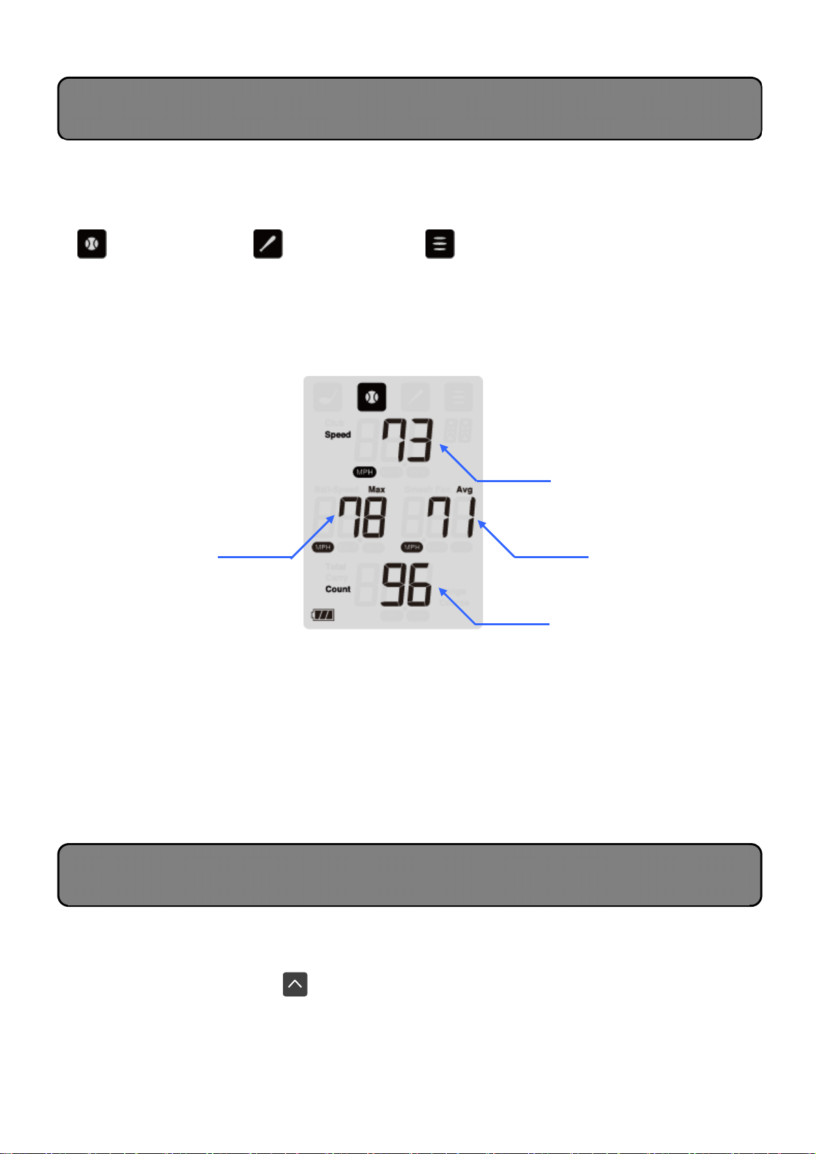
[Checking the Mode]
he selected mode can be checked by looking at the icon displayed at the top of the screen.
Make sure to select the correct mode for the measurement target.
Pitching mode Batting mode Multi mode
[Display Screen]
In addition to the measured speed, the maximum and average speeds saved to the history are
also displayed.
he total measurement count is also displayed.
[Regarding the Counter Function]
he Pitching, Batting, and Multi modes include a counter function displayed on the bottom of the
screen that tracks the measurement count. his function can be used to count the number of
practice swings and thrown balls.
*he counter can count up to 999. However, only up to 500 instances of measurement data
can be saved in the history (total for all modes).
*When the history is cleared, the count will also be cleared.
his device enables up to 500 instances of measurement data to be saved in the history (total for
all modes). Use the following procedure to display history data.
• Press the Up Scroll button .
⇒ he most previous measurement results will be displayed.
*You can continue to scroll by continuously pressing the Scroll buttons.
*When the total number of data reaches 500, the oldest data will be automatically overwritten.
Average speed
Measurement count
Measured speed
Description of Screen Displays
(Pitching/Batting/Multi Modes)
Checking History Data
Maximum speed

14
[Deleting History Data]
he history and count data in each mode can be deleted by continuously pressing the Up and
Down Scroll buttons simultaneously for 2 or more seconds.
Device Measurement Range and Setup
●
his device can be used to measure the speed of a ball passing through the following
general ranges.
he estimated ranges shown below are those when using a softball. Measurement may
not be possible depending on the ball material.
● If the device is set up at an angle in regards to an object’
s direction of travel, the speed
displayed will be slower than the actual speed.
Example: when measuring a target moving at 70 mph
0 degrees: 70 mph (100%)
10 degrees: 69 mph (98%)
0 degrees: 66 mph (94%)
30 degrees: 61 mph (87%)
3.5 ft 3.5 ft
3.5 ft
* Align the
bottom of the device with the target
direction
Set-up angle
Direction of travel
he units of measurement displayed on this device can be switched between imperial and
metric. Use the following procedure to switch the displayed units of measurement.
Switching displayed units of measurement
・Press and hold the Down Scroll button and EN ER button
simultaneously.
⇒ Every time the above buttons are pressed, the displayed units
of measurement will switch between imperial and metric.
“MPH” and “yard” ⇔ “km/h” and “m”
*Displayed unit of speed will switch on all modes.
*he operations and usage methods remain the
same for each mode.
*Next time the device is restarted, the displayed
units of measurement will be the same as those
when the device was turned off.
Switching units of measurement
Displayed unit
of speed
MPH ⇔ km/h
Displayed unit
of distance
yard
⇔
m

15
● Power doesn’t turn on
・ Check whether the orientation of the batteries is correct.
・ ake the batteries out before putting them back in. When doing so, check to make sure proper
contact is being made between metal portions.
・ Check the remaining battery power and replace with new batteries if necessary.
● Measurement isn’t possible
・ Check whether the device is set up correctly or try setting up the device again using the
methods described in this manual.
・ When a ball is launched at a high trajectory using a wedge club, etc., ball speed will be slower
and measurement may not be possible due to the specified smash factor not being met. ( his
is due to the specifications of the device and is not a malfunction.)
● Measurements seem incorrect
・ he club head speeds displayed by this device are those measured using our company’s
unique criteria. For that reason, measurements may differ from those displayed by
measurement devices from other manufacturers.
・ Check whether the device is set up correctly or try setting up the device again using the
methods described in this manual.
・ Correct ball speeds may not be displayed depending on the type of ball used. Also, the speeds
of plastic practice balls and sponge balls cannot be measured.
・ Only club head speed can be measured during practice swings.
In rare cases, ball speed and
flight distance may be displayed even during practice swinging, but this is due to noise and
such measurement results are not accurate.
Troubleshooting

16
●
M
icrowave sensor oscillation frequency: 24 GHz (K band) / ransmission output: 10 mW or less
●
Possible measurement range:
• Golf mode
Club head speed/ball speed: 25 mph - 200 mph
• Pitching/Batting modes
Swing speed/ball speed: 20 mph - 110mph
• Multi mode
Speed: 20 mph - 185 mph
●
Power: Power supply voltage = 6 V (using four AAA batteries) / Battery life: Approx. 1 month
when used 1 hr. per day
●
Operating temperature range: 0°C - 40°C / 32°F - 100°F (no condensation)
●
Device external dimensions: 55 mm × 116 mm × 48 mm / 2.2" × 4.6" × 1.9" (excludes
protruding sections)
●
Weight: 131 g (includes batteries)
In the event the device stops operating normally, stop use and contact the Inquiry Desk listed below.
● If a malfunction occurs over the course of normal use during the warranty period stated in the warranty,
we will repair the product free-of-charge in accordance with the content of this manual.
● If repairs are necessary during the warranty period, attach the warranty to the product and request the
retailer to perform repairs.
● Note that charges will be applied for repairs performed for the following reasons, even during the
warranty period.
(1) Malfunctions or damage that occur due to fire, earthquakes, wind or flood damage, lightning, other
natural hazards, or abnormal voltages
(2) Malfunctions or damage that occur due to strong impacts applied after purchase when the product
is moved or dropped, etc.
(3) Malfunctions or damage for which the user is deemed to be at fault, such as improper repair or
modification
(4) Malfunctions or damage caused by the product getting wet or being left in extreme environments
(such as high temperatures due to direct sunlight or extremely low temperatures)
(5) Changes in appearance, such as due to being scratched during use
(6) Replacement of consumables or accessories
(7) Malfunctions or damage that occur due to battery fluid leakage
(8) Malfunctions or damage deemed to have resulted from issues caused by the instructions in this
user’s manual not being followed
(9) I
f the warranty is not presented or required information (date of purchase, retailer name, etc.) is not filled in
* Disagreements regarding whether these exceptions apply, as well as the scope of warranty when
they do not apply, will be handled at our discretion.
● Please store this warranty in a safe location as it cannot be reissued.
* his warranty does not limit the legal rights of the customer. Upon expiration of the warranty period,
please direct any questions regarding repairs to the retailer from which the product was purchased
or to the Inquiry Desk listed above.
Specifications
Warranty and After-Sales Service
Inquiry Desk
AMH SPORTS
12222 Bell Ranch Drive , Santa Fe S rings , CA 90670 , U.S.A
TEL : (323)201
-
0880
FAX : (323)201
-
0884

17
Portable Launch Monitor HS-130A
Warranty
*his warranty is invalid if there is no information entered in the asterisk (*) fields.
When taking possession of the warranty, please check that the date of purchase,
retailer name, address, and telephone number have been filled in. Immediately
contact the retailer from which this device was purchased if any omissions are found.
PRGR CO., LTD.
5-36-11 Shimbashi, Minato-ku, okyo 105-0004 Japan
* Customer
Warranty period
1 year from date of purchase
* Date of purchase
DD/MM/YYYY
Serial No.:
Information for customers:
●his warranty promises that we will perform repair free-
of-charge in accordance
with the content of this manual.
Please read this manual carefully and ensure that all
items have been filled in.
●
Before requesting repairs, first take time to confirm that
the device power-
up procedures and operation methods
have been followed correctly.
Name:
Address:
(Postal code: )
elephone number:
* Retailer name/address/telephone number

18
Supplier's Declaration of Conformity
February 1, 2021
Unique Identifier
Portable Launch Monitor HS-130A
Party issuing Supplier’s Declaration of Conformity
PRGR CO.,LTD
5-36-11 SHIMBASHI, MINATO-KU, TOKYO 105-0004, JAPAN
TEL: +81-3-5400-4742
Responsible Party – U.S. Contact Information
AMH SPORTS
12222 Bell Ranch Drive , Santa Fe Springs , CA 90670 , U.S.A
TEL: 323-201-0880
FCC Compliance Statement (for products subject to Part 15)
This device complies with Part 15 of the FCC Rules. Operation is subject to the following
two conditions: (1) This device may not cause harmful interference, and (2) this device must
accept any interference received, including interference that may cause undesired operation.
Authorised Person
Hiroyoshi Hibino
President
Table of contents
Other PRGR Measuring Instrument manuals


