Durch ihn wird nicht nur die Abbildung, son-
dern auch der Klang beeinflusst, denn er
bestimmt das Verhältnis von Direktschall zu
reflektiertem Schall (Diffusschall): Bei geringem
Abstand klingt die Aufnahme ”trocken”, bei
großem Abstand wird ”mehr Raum” aufge-
nommen. Letzteres ist bei einer guten Akustik
meist erwünscht.
Zunächst sollte also unter klangästhetischen
Gesichtspunkten der Abstand gewählt werden,
wobei die akustischen Eigenschaften des Raums
mitbestimmend sind.
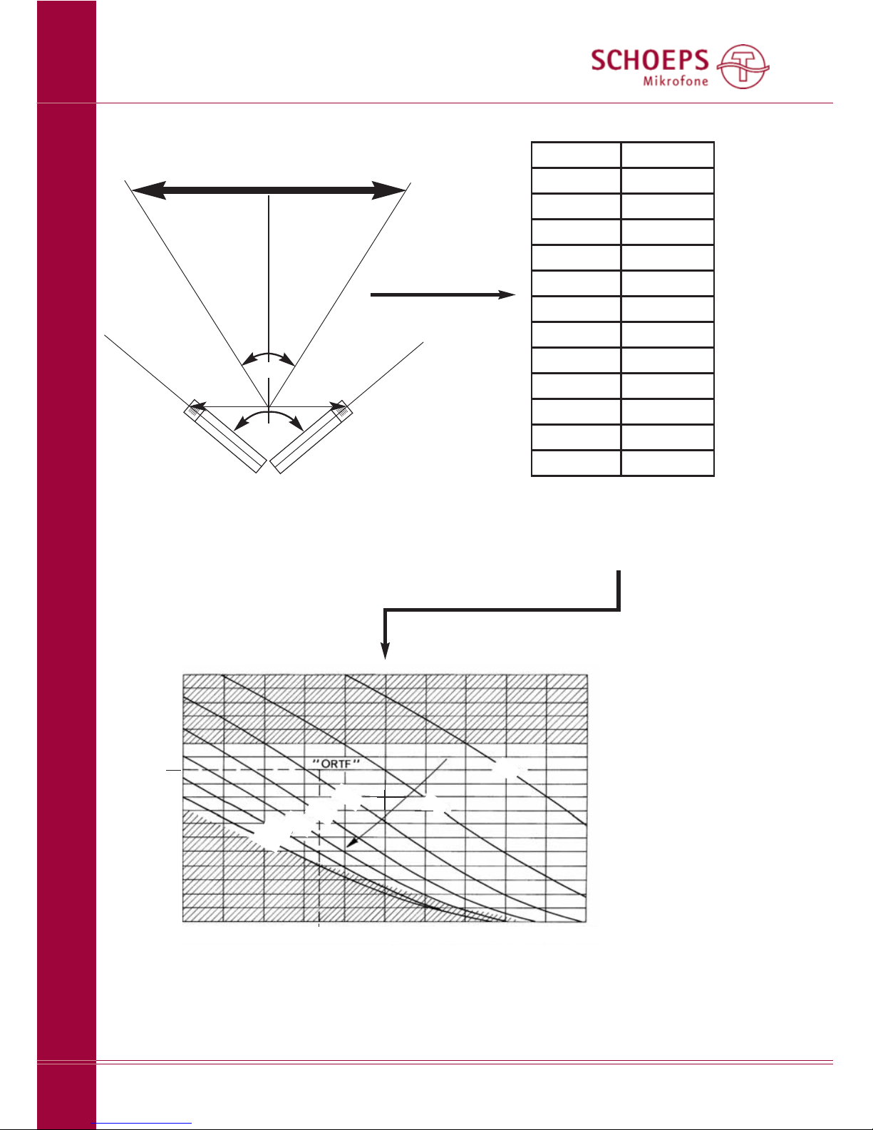
3. und 4.
Zur Bestimmung des Winkels
ω
und des
Abstands dzwischen den Mikrofonen muss
zunächst der Aufnahmewinkel
α
ermittelt
werden. Hierzu dient die Tabelle 1 auf Seite 5.
Der Aufnahmewinkel
α
ergibt sich aus dem
Verhältnis der Schallquellenbreite bzum
Abstand ader Mikrofone zur Schallquelle
(Abb. 9a). Hierzu müssen aund bentweder
geschätzt, abgeschritten oder abgemessen
werden.
Für den so ermittelten Aufnahmewinkel
sucht man in der Abbildung 9b die nächstge-
legene Kurve. Auf ihr liegen alle Einstellungen
für dund
ω
, die eine optimale Abbildung des
Aufnahmebereichs in den Wiedergabebereich
gewährleisten.
MS-Stereo
...mit axial besprechbaren Mikrofonen
(blaue Markierung; Abb. 3)
Mikrofone:
für das Mittensignal: meist eine Niere MK 4
oder Superniere MK 41, ggf. auch eine Kugel
(MK 2S oder MK 3);
für das Seitensignal: eine MK 8-Kapsel (oder
MK 6 in Position “Acht”).
Winkeln Sie die Klammern so an, dass sie
senkrecht von der Schiene weg weisen. Führen
Sie nun die Mikrofone ein. Die Klammern sol-
len die Mikrofone möglichst nahe am Stecker-
ende fassen. Winkeln Sie nun zunächst eine
der Klammern bis zum Anschlag zur Schienen-
mitte hin ab, dann die andere so weit, bis sie
die erste berührt. Stellen Sie sicher, dass die
Steckerenden der beiden Mikrofone bündig
übereinander liegen. Dann sind auch die Kap-
seln korrekt positioniert. Jetzt muss noch die
Aufnahmeachse des Seitenmikrofons (Acht)
ausgerichtet werden. Sie ist korrekt, wenn der
rote Punkt des Mikrofons zur linken Seite der
Schallquelle weist.
Weitere Informationen zu MS mit Niere
und Acht finden Sie in Abb. 10.
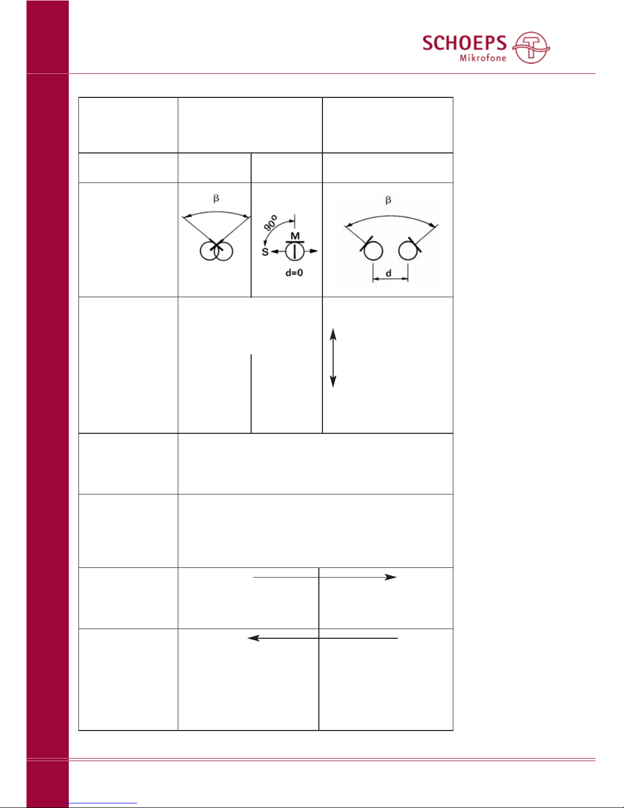
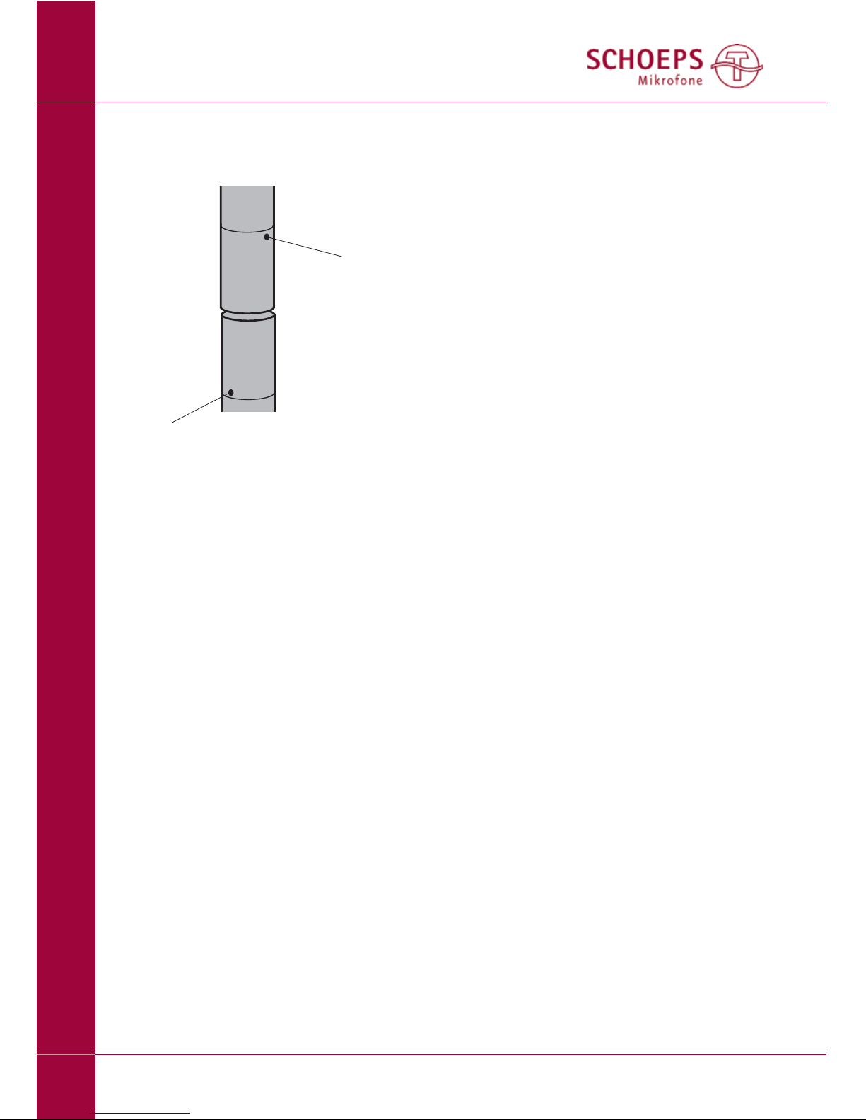
MS mit seitlich besprechbaren Mikrofonen
(rote Markierung; Abb. 4)
Mikrofone:
für das Mittensignal: meist eine Niere MK 4V
oder Superniere MK 41V;
für das Seitensignal: eine MK 8-Kapsel (oder
MK 6 in Position “Acht”).
Winkeln Sie die Klammern so an, dass sie senk-
recht von der Schiene weg weisen. Führen Sie
die Mikrofone jeweils etwa bis zur Mitte in die
Klammern ein. Sie sollten exakt in einer Geraden
ausgerichtet sein. Zwischen den Kapseln sollte
ein geringer Abstand bleiben (ca. 3mm).
Jetzt müssen noch die Aufnahmeachsen
– gekennzeichnet durch einen roten Punkt auf
den Kapseln – ausgerichtet werden. Ihre Orien-
tierung ist korrekt, wenn der rote Punkt des
Mittenmikrofons auf die Schallquelle gerichtet
ist, und der rote Punkt des Seitenmikrofons
nach links weist.
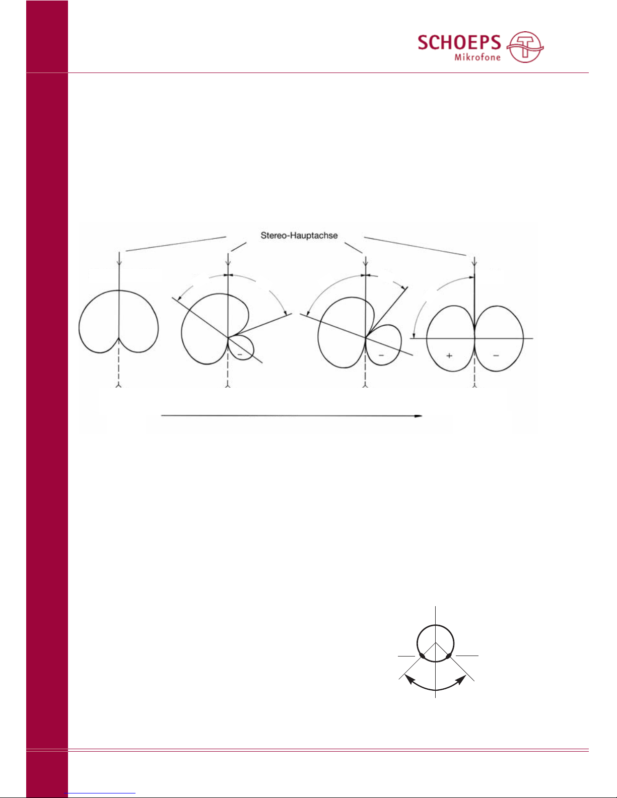
Ein häufiger Fehler bei MS
Die Kanäle “Links” und “Rechts” ergeben sich
aus den Signalen der Mitten- und Seitenmikro-
fone durch Summen- und Differenzbildung.
Im einfachsten Fall wird dies mit einem Mikro-
fonvorverstärker mit MS-Matrix realisiert.
Vorteil: Der Pegel bleibt bei Veränderung des
Anteils von M- und S-Signal konstant. Je nach
Gewichtung von M und S ergeben sich virtu-
elle, jeweils spiegelbildlich nach links und rechts
weisende Mikrofone (siehe Abb. 10). Mit dem
Basisbreitenknopf ändert sich sowohl deren
Richtcharakteristik als auch der Winkel zwi-
schen ihnen.
Beim Drehen an dem Basisbreitenknopf
(WIDTH) an einer MS-Matrix ist schon mancher
Opfer von folgendem Sachverhalt geworden:
In obiger Abbildung erkennt man, dass eine
SCHOEPS GmbH · Spitalstr. 20 · D-76227 Karlsruhe (Durlach) · Tel: +49 721 943 20-0 · Fax: +49 721 943 2050
MS-Stereo
7
Deutsch