schroff CPCI PICMG 2.16 Operation manual

10001001
74579-028 Rev.001
Notice pour utilisateur de
Systèmes d'i tégratio de
cartes à microprocesseurs
Be utzeri formatio
Mikrocomputer
Aufbausystem
CPCI PICMG 2.16
Ei schubsystem 10 HE
(24579-028)
User I formatio
Microcomputer
Packagi g Systems
CPCI PICMG 2.16
subrack 10 U
(24579-028)

CPCI PICMG 2.16 10 HE
1.2
I halt
I haltsverzeich is Deutsch, Seite ............................. 1.2
Seite
1 Ei führu g ................................................................. 1.2
1.1 Bitte sofort lesen! ......................................................... 1.2
1.2 Kurzbeschreibun ....................................................... 1.3
1.3 Sicherheitshinweise ..................................................... 1.3
1.4 All emeine Hinweise ................................................... 1.3
2 Systemübersicht ........................................................ 1.4
2.1 Mechanischer Aufbau .................................................. 1.4
2.2 Monta e ...................................................................... 1.5
2.3 Inbetriebnahme ........................................................... 1.5
2.4 Wartun ....................................................................... 1.5
3 Elektrischer Aufbau .................................................. 1.5
3.1 Verdrahtun splan all emein ........................................ 1.5
3.2 Fan Control Modul (FCM) ............................................ 1.6
4 Tech ische Date ...................................................... 1.7
4.1 Mechanische Daten ..................................................... 1.7
4.2 Elektrische Daten ........................................................ 1.7
4.2.1 Stromversor un en ..................................................... 1.7
4.2.2 Fan Control Modul (FCM) ............................................ 1.8
4.2.3 Ventilator ..................................................................... 1.8
4.2.4 Busplatine .................................................................... 1.8
4.3 All emeine Daten ........................................................ 1.8
4.4 Schirmdämpfun skurven europacPRO ....................... 1.9
4.4.1 Messprinzip ................................................................. 1.9
4.4.2 Messer ebnisse .......................................................... 1.9
5 Störu gs- u d Fehlersuche ...................................... 1.10
6 Ersatzteile .................................................................. 1.10
7 Gara tie-Bedi gu ge .............................................. 1.10
1 Ei führu g
1.1 Bitte sofort lese !
Das Mikrocomputer-Aufbausystem ist kein komplettes Gerät, wel-
ches unmittelbar an den Endbenutzer aus eliefert werden kann,
dazu sind weitere Ausbauten notwendi . Vor der Auslieferun des
ferti en Gerätes muss überprüft werden ob:
das komplettierte Gerät den aktuellen und im Benutzun sland
eltenden Sicherheitsbestimmun en entspricht.
sämtliche Öffnun en des Gehäuses eschlossen sind, damit
der Benutzer das Innere des Gehäuses nicht erreichen kann
(Prüffin er).
Sie sollten sicherstellen, dass
alle Sicherheitsprüfun en an jedem Gerät durch eführt
werden,
der Betreiber erfährt, welche Sicherheitsmassnahmen er
er reifen muss (z.B. Erdun ),
das esamte Gerät allen sonsti en Vorschriften am
Benutzun sort und im Benutzun sland entspricht, z.B.
Störstrahlun s renzen, Zulassun durch Fernmeldebehörden
(ZZF, FCC usw.).
Dies setzt voraus, dass die Ei ga gsprüfu g, Komplettie-
ru g u d E dprüfu g der Geräte durch Fachperso al vorge-
omme oder überwacht werde . Diese A leitu g richtet
sich ausschliesslich a dieses Fachperso al.
Sehen Sie die Verpackun nach fol enden Beila en durch:
1 Beutel mit Befesti un smaterial zum Einbau des
Einschubsystems in ein Gehäuse oder einen Schrank.
U mittelbar ach dem Auspacke Sicherheits- u d Fu kti-
o sko trolle durchführe , siehe Absch itt "Ei führu g –
Sicherheitshi weise". Kei e Haftu g für Karte , die durch
fehlerhafte Betriebsspa u ge zerstört wurde !
Bei Problemen wenden Sie sich bitte an Ihren Lieferanten oder
direkt an die zuständi e Schroff-Vertretun (siehe Umschla rück-
seite).

CPCI PICMG 2.16 10 HE
1.3
1.2 Kurzbeschreibu g
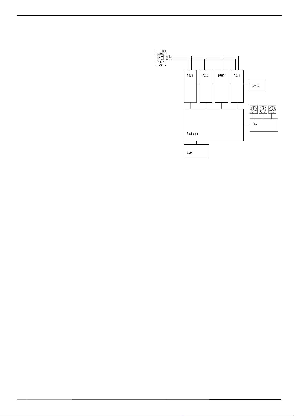
Das Mikrocomputer-Aufbausystem besteht aus Mechanik, Rück-
verdrahtun splatte (weiter "Busplatine" enannt), Lüftun und
Stromversor un für ein Mikroprozessor-System auf CPCI
PICMG2.16bus-Basis.
Das Mikrocomputer-Aufbausystem ist für den Betrieb im Laborbe-
reich oder in der Ferti un ohne extreme Umweltanforderun en
edacht:
Beachten Sie die technischen Daten der Teile, die Sie einbauen
möchten. G f. können diese speziell den Temperaturbereich wei-
ter einen en.
Dieses Aufbausystem bri gt die Voraussetzu ge mit, um
die übliche Zulassu gsverfahre zu bestehe . Ei e Zulas-
su g kö e Sie ur für das komplette Gerät erwerbe ,
i dem Sie ei e Ei zel- oder Serie zulassu g durchführe
lasse . Diese Zulassu ge führe je ach A we du gsfall
VDE, TÜV, Berufsge osse schafte usw. durch.
ACHTUNG!
Das Gerät ist entsprechend Schutzklasse 1 aus eführt! Deshalb:
Betrieb nur mit Schutzleiteranschluss!
1.3 Sicherheitshi weise
Das Microcomputer-Aufbausystem hat vor Auslieferun umfan -
reiche Prüfun en durchlaufen. Trotzdem sollten Sie sich davon
überzeu en, dass das Gerät den Transport unbeschadet über-
standen hat. Eine erneute Prüfun des Schutzleiterwiderstandes
und der CPCI-Spannun en muss durch eführt werden, um sicher-
zustellen, dass Ihre Anwender-Karten nicht durch falsche
Betriebsspannun en beschädi t werden.
Vorsicht:
Der nach Ausbau der Netzein än e zu än liche Bereich des
Systems ist kein Benutzerbereich! Berührbare Teile können
unter Spannun stehen. Ein an sprüfun , Komplettierun ,
Endprüfun bzw. Wartun und Instandsetzun der Geräte darf
nur durch Fachpersonal vor enommen werden. Diese Anlei-
tun richtet sich ausschliesslich an dieses Fachpersonal, d.h.
In enieure, Techniker, Facharbeiter, unterwiesenes Personal.
Abschliesse de Arbeite vor I betrieb ahme:
Vor Be inn der Arbeiten Netzstecker ziehen!
A der Rückseite:
Mit Schraubendreher Sicherun shalter öffnen.
Korrekte Sicherun ein ebaut?
Die Netzein anssicherun ab Werk ist für die maximale
Leistun den Netz erätes aus ele t. Die Sicherun muss
vor Inbetriebnahme an die tatsächliche Stromaufnahme
des komplettierten Systems an epasst werden.
Maximalwerte sind 10A trä e .
A der Fro tseite:
Alle Steckplätze und Laufwerköffnun en mit Frontplatten
verschlossen?
Ventilatorfrontplatte und Netz eräte fest eschraubt?
1.4 Allgemei e Hi weise
Vorsicht:
- Sicherheitsvorschriften und -bestimmun en und Warnhinweise
beachten
- vor Betrieb Bedienun sanleitun lesen!
- nur an Netzen mit Schutzleiter betreiben!
- die Inbetriebnahme darf nur von technisch unterwiesenem
Personal durch eführt werden!
Sicherheitshi weise beachte
Sie sollen
- Leben schützen
- Unfälle vermeiden
- Är er ersparen
Diese Bedienun sanleitun ut aufbewahren, sie enthält wichti e
Sicherheitshinweise. Die Bedienun sanleitun
- unterstützt Bediener, Benutzer, Servicemitarbeiter und
eschultes Fachpersonal bei den vorbereitenden Arbeiten, dem
Einbau, Inbetriebnahme und dem Verständnis für die Funktionen
des Gerätes;
- ibt Hinweise auf besondere Betriebs- und Einsatzbedin un en;
- erklärt die Anzei e und Bedienelemente;
- nennt alle wichti en technische Daten.
Technische Änderun en und Verbesserun en werden ohne vor-
heri e Ankündi un in die Produktion übernommen wenn diese
dem technischen Fortschritt dienen.
Dieses Produkt ist nur für den ewerblichen und industriellen
Gebrauch bestimmt. Es ist nicht im Einsatz im Zusammenhan mit
lebenserhaltenden medizinischen Geräten oder für andere kriti-
schen Einsätze vor esehen.
Diese Dokume tatio wurde mit grösster Sorgfalt erstellt u d
geprüft; de och kö e wir für die vollstä dige Richtigkeit
dieser A leitu g, für Schäde i folge Druckfehler, Be utzer-
fehler oder u sachgemässe Nutzu g kei e Gara tie über-
ehme .
Bei u sachgemässer Ha dhabu g erlösche die Gara tiea -
sprüche!
Hi weis
beachte
Lebe sgefahr

CPCI PICMG 2.16 10 HE
1.4
2 Systemübersicht
2.1 Mecha ischer Aufbau
1 Chassis
2 zwei Netz eräte oben
3 Steckplatz für zwei Netz eräte unten
4 zwei Steckplätze für CMMs
5 Kartenkorb
6 Lufteinlass, dahinter Lüftereinschub und Luftfilter
7 Backplane
8 Verdrahtun
9 Netzein än e
10 Rear-I/O
12302505
Frontansicht:
12302006

CPCI PICMG 2.16 10 HE
1.5
2.2 Mo tage
Der vordere Kartenkorb kann mit 6 HE / 4 TE-CPCI PICMG 2.16-
Karten bestückt werden. Der rückwärti e Kartenkorb wird mit
6 HE / 4 TE-Rear-I/O-Karten aus estattet. Die Karten werden
jeweils in den Führun sschienen ein eschoben und mittels den
Halsschrauben an der Frontplatte esichert. Die Führun sschie-
nen der Systemslots sind rot. Die blauen Führun sschienen kenn-
zeichnen die Fabric-Slots. Die Netz erätesteckplätze ermö lichen
den Einsatz von bis zu vier 3HE-CPCI-Netz eräten. Die entspre-
chenden Führun sschienen sind rün aus eführt.
Nicht benutzte 6HE-Steckplätze müssen mit Frontplatten mit Luft-
schottblechen, nicht benutzte Netz eräte-Steckplätze mit Front-
platten verschlossen werden. Nur so kann eine optimale Belüftun
des Kartenkorbs ewährleistet werden.
Der Bau ruppenträ er wird mit den acht mit elieferten Schrauben
am Holm eines 19"-Schrankes montiert.
2.3 I betrieb ahme
Die Netzsicherun muss aus etauscht werden. Sie muss an die
tatsächliche Stromaufnahme des komplettierten Systems an e-
passt werden. Nach dem Anschluss an die Netzversor un wird
das System mit dem Netzschalter ein eschaltet. Die rünen
Leuchtdioden an den Netz eräten si nalisieren den störun s-
freien Betrieb. Jeweils eine rote LED si nalisiert den estörten
Betrieb.
2.4 Wartu g
Die Lüftereinschübe lassen sich nach Lösen der Halsschrauben
und Aufklappen der Frontplatte (Position 6, Kapitel Mechanischer
Aufbau) herausziehen. Der Austausch eines defekten Ventilator-
einschubs kann in laufendem Betrieb durch eführt werden.
Die Filtermatte ist unterhalb des Lüftereinschubs zu än lich. Sie
sollte, in Abhän i keit des Verschmutzun s rades der Um e-
bun , in re elmässi en Abständen aus etauscht werden.
3 Elektrischer Aufbau
3.1 Verdrahtu gspla allgemei
10002500

CPCI PICMG 2.16 10 HE
1.6
3.2 Fa Co trol Modul (FCM)
Das Fan Control Modul ist ein microcontroller-basierte, tempera-
turabhän i e Drehzahlsteuerun von bis zu 4 DC-Lüftern
Es ermö licht den Anschluss von bis zu 4 Temperatursensoren
(NTC)
Es überwacht die Solldrehzahl jedes Lüfters.
Bei Solldrehzahl-Unterschreitun (z.B. La erschaden oder Aus-
fall) sowie Kabelbruch oder Kurzschluß der Temperaturfühler-Lei-
tun wird eine Alarmmeldun eneriert und die Lüfter mit 100%
Drehzahl an esteuert.
Das FCM besitzt eine Anbindun zum CMM (I2C-bus) zur Fern-
meldun von Alarmen und zur individuellen Parametrierun des
FCMs.
Blockschaltbild:
10002501
Kennlinie der Kühlun :
+3.3V monitor in
+12V monitor in
-12V monitor in
υ
υ
υ
υ
I2C bus to CMM
I2C bus
Volta e fail + 5V LED
Volta e fail +3.3V LED
Volta e fail +12V LED
Volta e fail –12V LED
Di ital input 1
Di ital input 2
Di ital input 3
Di ital input 4
Fan Fail LED
Over Temp LED
Over Temp di ital outpu
t
Fan Fail di ital output
Filter
NTC 1
NTC 2
NTC 3
NTC 4
Fan 1
Fan 2
Fan 3
Fan 4
5
V Module power
µCDriver
Fan speed characteristics
Fan speed
(%)
υ (°C)
100
60
25 50 60
Over Temp
Alarm
Steckerbelegu g:
X1:Steckverbi der für Sig ale u d Spa u gsversorgu g
X2:Steckverbi der für Temperaturse sore u d digitale
Ei gä ge
Bezeich u g Klemme Fu ktio
12V 1 Power for fan;
Current: 3A
-12V 8 Ground for fan
Current: 3A
12V 2 LED display
-12V 9 LED display
3,3V 3 LED display
5V 10 Power for lo ic
current: 0,5A
GND 11 Ground for lo ic
current: 1A
Temp Fail collec-
tor 4 Si nal out
Temp Fail emit-
ter 5 Si nal out Ground
Fan Fail collector 6 Si nal out
Fan Fail emitter 7 Si nal out Ground
CMM BUS SCL 13 Communication Bus
CMM BUS SDA 12 Communication Bus
CMM BUS GND 14 Communication Bus
Bezeich u g Klemme Fu ktio
Di ital in1 TTL 7 Si nal in
Di ital in2 TTL 8 Si nal in
Di ital in3 anode 9 Si nal in
Di ital in3 ca-
thode 10 Si nal Ground
Temp 1 + 1 Te mp sen so r
Temp 1 - 2 Te mp sen so r
Temp 2 + 3 Te mp sen so r
Temp 2 - 4 Te mp sen so r
Temp 3 + 5 Te mp sen so r
Temp 3 - 6 Te mp sen so r

CPCI PICMG 2.16 10 HE
1.7
4 Tech ische Date
4.1 Mecha ische Date
Mechanik nach IEC 60297, IEEE 1011.10/11
Maße
H x B x T = 445mm (10HE) * 483mm (19“) * 325mm
Gewicht (oh e Karte )
20 k
Kühlu g
Erfol t mit drei Axialventilatoren.
Der maximale Gesamtvolumenstrom beträ t 275 m³/h. Die
durchschnittliche Temperaturerhöhun im Einschub bei Voll-
last ist 12 K. Die Drehzahl der Ventilatoren wird in Abhän i -
keit von der Temperatur ere elt. Die Re elun erfol t
zwischen 20°C und 50°C, im Drehzahlbereich zwischen 60%
und 100% der Maximaldrehzahl.
100 02 502
4.2 Elektrische Date
4.2.1 Stromversorgu g
Daten eines einzelnen Netz eräts:
Netzspannun
(Arbeitsbereich) 85-264Vac
Netzfrequenz 47-63Hz
Einschaltstrom max.12A
Gesamtaus an sbelastbar-
keit max. 250W
Aus an sspannun :
max. Einzelstrom
+ 5 V
+3,3V
+ 12 V
- 12 V
40 A
40A
5,5A
1,5A
Restwelli keit 2%
Dynamischer Lastsprun
50%->100% 1%
Ausre elzeit nach Einschalten 150ms
Netzausfallüberbrückun 20ms

CPCI PICMG 2.16 10 HE
1.8
4.2.2 FCM (Fa Co trol Modul)
4.2.3 Ve tilatore
4.2.4 Busplati e
Technische Daten etc. siehe in der Bedienun sanleitun der Bus-
platine .
Versor un sspannun
Ein an sstrom +5V
500mA
mechanische Abmessun en 38mm x 160mm x 25mm (LxBxT)
Schnittstellen
4 Di italein än e TTL-Pe el
2 Di italaus än e, alvanisch etrennt
durch Optokoppler
4 Zählein än e zur Lüfterüberwachun
Versor un von bis zu vier Lüftern
max. 2,5A
4 NTC-Messein än e
Interface zu CMM via I²C-Bus
Nominalspannun 24 VDC
Stromverbrauch 3 x 0,68A
Luftfördermen e
freiblasend 3 x 294 m3/h
Geschwindi keit 3800 min-1
Tachoaus an Zwei Impulse pro Umdrehun
Abmessun en einzeln 127mmx127mmx38mm
4.3 Allgemei e Date
Sicheru gswert (maximal)
10 A trä e 250V
Prüfspa u ge ach EN 60950
Zulassu ge
Umgebu gstemperatur
Feuchtigkeit
30 – 80 %, nicht kondensierend
Schock u d Vibratio
nach EN 60068-2-6 und EN 60068-2-27
Schutzart: IP 20
Überspannun skate orie II
Schutzklasse 1
Sicherheit
Das von Schroff elieferte Gerät erfüllt
die Norm EN 60950
Schirmu g
Schirmdämpfun typisch 40 dB bei 1 GHz unter Voraussetzun ,
dass die Frontseite mit eschirmten Frontplatten verschlossen
werden.
Durch den Einbau weiterer Elektronikkomponenten können sich
die Sicherheit und die EMV Daten ändern.
Das komplettierte System muss erneut auf das Einhalten der
enannten Ei enschaften eprüft werden.
Ein an - Aus an 4,3 KVDC
Ein an - PE 2,2 KVDC
Aus an - PE 0,7 KVDC
Aus an - Aus an 0,7 KVDC
Bauteil VDE UL
Netzstecker * *
Netzschalter * *
Netz erät * *
Betrieb 0 °C ........+ 40 °C
La erun - 40 °C ...+ 85 °C

CPCI PICMG 2.16 10 HE
1.9
Elektromag etische Verträglichkeit
Mikrocomputer-Aufbausysteme sind keine Endprodukte. Um eine
ei enständi e Funktion auszuführen, sind weitere Ausbauten not-
wendi . Entsprechend der Definition im EMV-Gesetz handelt es
sich um keine Apparate. Eine CE-Kennzeichnun ist daher nicht
anzuwenden.
Die Systeme erfüllen jedoch alle Voraussetzun en, um im aus e-
bauten Zustand die Normen emäß der EMV-Richtlinie 89/336/
EWG und der Niederspannun srichtlinie 73/23/EWG einzuhalten.
Die Systeme werden enerell mit Netz eräten aus estattet, die
eine CE-Kennzeichnun aufweisen.
Die Auswahl der Netzfilter-Elemente erfol t unter Berücksichti-
un der Grenzwertkurve nach EN55022 Klasse B. Hausinterne
Meßeinrichtun en erlauben hierbei eine präzise Auswahl der Fil-
ter.
Um für die Störfesti keit entsprechend EN61000-6-2 bestens
erüstet zu sein, werden bei der Entwicklun der Schroff - Bau-
ruppenträ er und - Gehäuse Schirmdämpfun smessun en
durch eführt. Diese Messun en beinhalten den Frequenzbereich
von 30 MHz bis 1000 MHz und sind an elehnt an VG-Bestim-
mun 95 373, Teil 15.
4.4 Schirmdämpfu gskurve europacPRO
4.4.1 Messpri zip
Die Schirmdämpfun technischer Schirmhüllen wird über die Mes-
sun der
Einfügungsdämpfung
des Prüfobjekts bestimmt. Das
Messprinzip beruht auf einer Differenzmessun , bei der man am
Empfän er zunächst anhand einer Leermessun (Bild 2a) den
Feldstärkepe el A0 (ohne Gehäuse) ermittelt, danach den Feld-
stärkepe el A1 (mit Gehäuse in Bild 2b) mißt und die Differenz der
beiden Pe el bildet. Eine Kalibrierun des Empfän ers ist dabei
nicht erforderlich. Der Feldstärkepe el A0 wird auch als Referenz-
pe el bezeichnet.
Bild 2a
Bild 2b
Messun der Einfü un sdämpfun technischer Schirmhüllen
(Prinzip).
a) Messun ohne Prüfobjekt,
b) Messun mit Prüfobjekt.
Die Schirmdämpfun as errechnet sich fol lich zu,
4.4.2 Messergeb isse
Schirmdämpfun im Bereich von 30 MHZ bis 1 GHz,
Bau ruppenträ er europacPRO, Textildichtun
Einstrahlun auf Frontseite, Polarisation vertikal.
as = A0 – A1 i dB.

CPCI PICMG 2.16 10 HE
1.10
5 Störu gs- u d Fehlersuche
6 Ersatzteile
Fehlerart mögliche Ursache Fehlerbehebu g
weder rote
noch rüne
LED der
Netz eräte
leuchten
Netzspannun ist nicht vor-
handen Netzzuleitun prüfen
rote LED ei-
nes Netz e-
räts leuchtet das Netz erät ist defekt Netz erät tauschen
Ersatzteil Artikel-Nr.
Filtermatte 418*168 64495-001
Busplatine 23006-610
FCM 43207-062
CMM 43207-056
Netz erät 13100-141
Slotabdeckun , 6 HE
1 Slot, 4 TE 34562-826
2 Slot, 8 TE 34562-836
3 Slot, 12 TE 34562-846
7 Gara tiebedi gu ge
Leistu gsdauer
Für dieses Gerät
leisten wir 2 Jahre Garantie. Der Anspruch
be innt mit dem Ta der Auslieferun .
Umfa g der Mä gelbeseitigu g
Innerhalb der Garantiezeit beseiti en wir kostenlos alle Funktions-
fehler an diesem Gerät, die auf man elhafte Ausführun bzw.
Materialfehler zurückzuführen sind. Weiter ehende Ansprüche -
insbesondere für Fol eschäden - sind aus eschlossen.
Gara tieausschluss
Schäden und Funktionsstörun en, verursacht durch Nichtbeach-
ten unserer Benutzerinformation sowie Fall, Stoß, Verschmutzun
oder sonsti e unsach emässe Behandlun fallen nicht unter die
Garantieleistun en. Die Garantie erlischt, wenn an dem Gerät,
unsach emässe Ein riffe vor enommen werden bzw. die Serien-
nummer am Gerät verändert oder unkenntlich emacht wurde.
Abwicklu g des Gara tiea spruches
Das Gerät wurde sor fälti eprüft und ab e lichen. Sollten den-
noch berechti te Beanstandun en entstehen, ehen Sie bitte zur
Erhaltun Ihres Garantieanspruches wie fol t vor:
Le en Sie bitte eine mö lichst enaue Beschreibun der
Beanstandun bei.
Senden Sie das Gerät im Ori inal-Karton oder leichwerti er
Verpackun versichert und portofrei an uns zurück.
Bei unsach emässer Handhabun erlöschen die Garantieansprü-
che!
Diese Dokumentation wurde mit rösster Sor falt erstellt und
eprüft; dennoch können wir für die vollständi e Richti keit keine
Garantie übernehmen.

CPCI PICMG 2.16 10 U
1.2
Co te ts
Co te ts E glish, page .............................................. 1.2
Seite
1 I troductio ............................................................... 1.2
1.1 Please read immediately! ............................................ 1.2
1.2 Description .................................................................. 1.3
1.3 Safety instr ctions ....................................................... 1.3
1.4 Advice .......................................................................... 1.3
2 System overview ........................................................ 1.4
2.1 Mechanical config ration ............................................. 1.4
2.2 Assembly ..................................................................... 1.5
2.3 Starting- p the system ................................................. 1.5
2.4 Maintenance ................................................................ 1.5
3 Electrical co figuratio ............................................. 1.5
3.1 Cabling, general ........................................................... 1.5
3.2 Fan Control Mod le (FCM) .......................................... 1.6
4 Tech ical data ............................................................ 1.7
4.1 Mechanical data .......................................................... 1.7
4.2 Electrical data .............................................................. 1.7
4.2.1 Power s pply ............................................................... 1.7
4.2.2 Fan Control Mod le (FCM) .......................................... 1.8
4.2.3 Fan .............................................................................. 1.8
4.2.4 Backplane .................................................................... 1.8
4.3 General data ................................................................ 1.8
4.4 Shielding atten ation c rve e ropacPRO .................... 1.9
4.4.1 Mes ring principle ....................................................... 1.9
4.4.2 Res lts ......................................................................... 1.9
5 Error correctio ......................................................... 1.10
6 Replaceme t parts .................................................... 1.10
7 Warra ty co ditio s .................................................. 1.10
1 I troductio
1.1 Please read immediately!
This microcomp ter packaging system is not a complete nit
which can be delivered directly to the end ser; other items need to
be fitted. Before deliverying the complete nit, the following checks
m st be carried o t according to the specifications:
does the assembled nit comply with the safety instr ctions
c rrently applicable in the co ntry in which it is going to be
sed?
are all the apert res of the case closed so that the ser cannot
get into the case (finger test)?
Make s re that
all safety checks have been carried o t on every nit,
the operator knows what safety meas res have to be
ndertaken (e.g. GND/earthing),
the overall nit complies with all other specifications at the
place of se and in the co ntry in which it is going to be sed,
e.g. interference limits, approval by the telecomm nications
a thorities.
The above assumes that the i itial testi g, completio a d
fi al testi g of the u its have bee carried out or at least
supervised by qualified tech icia s. These i structio s are
directed exclusively to these qualified tech icia s.
Check the packing material. At least the following sho ld be incl -
ded:
1 bag of assembly parts for mo nting the system s brack into
a case or cabinet
Whe the u it has bee u packed the safety a d fu ctio
checks should be carried out immediately, see sectio
"I troductio – Safety i structio s". No liability is accepted
for boards which have bee destroyed by faulty operati g
voltages!
If there are problems please contact yo r s pplier or yo r local
Schroff representative, see back cover of this booklet.

CPCI PICMG 2.16 10 U
1.3
1.2 Descriptio
This microcomp ter packaging system consists of mechanics,
backplane, fan and power s pply for a microprocessor system
based on the CPCI PICMG2.16b s. This microcomp ter
packaging system has been designed for se in laboratories or in
a man fact ring environment where there are no extreme
conditions.
Please check the technical data of any parts which yo wish to
assemble; they may restrict in partic lar the temperat re range.
This u it has o valid approval for the complete u it. This
ca o ly gra ted for the complete u it if approval is gra ted
for i dividual u its or a batch. Such approvals are carried out
by VDE, TÜV, professio al boards etc. accordi g to each
applicatio .
CAUTION!
The nit is designed in accordance with protection class 1!
It must therefore be operated o ly with protective GND/earth
co ectio !
1.3 Safety i structio s
This microcomp ter packaging system has been s bjected to
extensive testing before delivery. However, this cannot g arantee
that the nit does not get damaged d ring transit. Check the
protection resistance and the CPCI voltage to ens re that yo r
system can not be destroyed by fa lty operating voltages.
Cautio :
The area of the system accessed after removing the mains/line
entrances is not a ser area! Parts which can be to ched may
be exposed to dangero s voltages. Initial testing, completion,
final testing or maintenance and repairs m st be carried o t by
trained engineers only.
The followi g tests have to be do e before placi g the
system i service:
Disconnect the main/line voltage!
At the rear:
Open the f se holder with a screwdriver.
Is the correct f se fitted?
The f se val e has been determined in factory for the
maximal power delivered by the power s pply. The f se
val e m st be adj sted to the real c rrent of the global
system. Maxim m val es are 5 A slow.
At the fro t:
Are front panels mo nted to all connector positions and
disk drive apert res?
Are fans front pannel and power s pplies screwed on?
1.4 Advice
Cautio :
- please observe the safety instr ctions
- read operating instr ctions before system start- p!
- to be operated only on nets with PE cond ctor!
- p tting into service by q alified personnel only!
Safety i structio s
are meant to
- save lives
- prevent accidents
- save tro ble
Please make s re to keep these operating instr ctions. It contains
val able information pertaining to safety.
It
- s pports operators, sers, service staff and technical personnel
d ring preparatory work, installation and system start- p, and it
helps nderstand the f nctions of the system
- gives hints as to special operating conditions
- explains the displays and control elements
- informs abo t all essential technical data
Technical changes and pgrades will be implemented witho t
prior anno cement, provided that they serve technical progress.
This prod ct is intended excl sively for commercial and ind strial
applications. It is not designed for se in connection with
life-s pporting medical eq ipment or other critical applications.
This docume tatio has bee prepared a d checked with
greatest care. However, we ca ot give guara tee for its
complete correct ess, for a y damage resulti g from
mispri t or improper use.
I the case of improper use all warra ty claims will lapse!
Atte tio
Da ger to life

CPCI PICMG 2.16 10 U
1.4
2 System overview
2.1 Mecha ical co figuratio
1 Chassis
2 Two power s pplies on the top
3 Slot for two power s pplies on the bottom
4 Two slots for CMMs
5 S brack
6 Air entry with fan tray and air filter
7 Backplane
8 Cable
9 Mains/line connection
10 Rear-I/O
12302505
Front view:
12302006

CPCI PICMG 2.16 10 U
1.5
2.2 Assembly
The s brack can be eq ipped with 6 U/ 4 F CPCI PICMG 2.16
boards on the front and 6 U/ 4 F boards with rear I/O on the back.
Boards are mo nted in g ide rails and fixed with collar screws.
The g ide rails from the system slot are red. The bl e g ide rails
characterize the Fabric slots. Up to fo r 3 U CPCI power s pplies
can be integrated sing the green g ide rails.
For an optimal heat dissipation, n sed 6 U slots m st be closed
with air flow barrier front panels, n sed power s pply slots with
front panels.
The s brack can be mo nt on the cabinet‘s pright sing the eight
delivered screws.
2.3 Starti g-up the system
The mains/line f se val e m st be adj st to the real c rrent
cons mption of the complete system. Connect the system to the
mains/line and switch it on by sing the mains/line switch. Green
LEDs on the power s pplies indicate that the voltages exist. Red
LEDs indicate a damage.
2.4 Mai te a ce
In order to remove the fan mod les, loos the collar screws and
hinged the front panel (Position 6, chapter Mechanical constr c-
tion). A fa lty fan can be replace while the system is operating.
The air filter is accessible nderneath the fan tray. The filtre m st
be change reg rlarly, depending on the environmental conditions.
3 Electrical co figuratio
3.1 Cabli g, ge eral
10002500

CPCI PICMG 2.16 10 U
1.6
3.2 Fa Co trol Modul (FCM)
The Fan Control Mod le, based on a microcontroller, monitors p
to 4 DC fans rotation speed depending on the temperat re.
Up to 4 temperat re sensors (NTC) can be connected.
It controls the theoretical speed val e of each fan.
If the fan speed falls below the theoretical val e or by cable
damage or by temperat re sensor cable short-circ it, an alarm is
generated and the fans rotate at their maxim m speed.
The FCM has a CMM connection (I2C-b s) for remote alarm
signal and for individ al config ration of the FCMs.
Block diagram:
10002501
Fan speed characteristics:
+3.3V monitor in
+12V monitor in
-12V monitor in
υ
υ
υ
υ
I2C b s to CMM
I2C b s
Voltage fail + 5V LED
Voltage fail +3.3V LED
Voltage fail +12V LED
Voltage fail –12V LED
Digital inp t 1
Digital inp t 2
Digital inp t 3
Digital inp t 4
Fan Fail LED
Over Temp LED
Over Temp digital o tp
t
Fan Fail digital o tp t
Filter
NTC 1
NTC 2
NTC 3
NTC 4
Fan 1
Fan 2
Fan 3
Fan 4
5
V Mod le power
µCDriver
Fan speed characteristics
Fan speed
(%)
υ (°C)
100
60
25 50 60
Over Temp
Alarm
Co ectors assig me t:
X1:Co ector for sig als a d power supply
X2:Co ector for temperature se sors a d digital i puts
Desig atio Termi al Fo ctio
12V 1 Power for fan;
C rrent: 3A
-12V 8 Gro nd for fan
C rrent: 3A
12V 2 LED display
-12V 9 LED display
3,3V 3 LED display
5V 10 Power for logic
c rrent: 0,5A
GND 11 Gro nd for logic
c rrent: 1A
Temp Fail
collector 4 Signal o t
Temp Fail
emitter 5 Signal o t Gro nd
Fan Fail collector 6 Signal o t
Fan Fail emitter 7 Signal o t Gro nd
CMM BUS SCL 13 Comm nication B s
CMM BUS SDA 12 Comm nication B s
CMM BUS GND 14 Comm nication B s
Desig atio Termi al Fo ctio
Digital in1 TTL 7 Signal in
Digital in2 TTL 8 Signal in
Digital in3 anode 9 Signal in
Digital in3
cathode 10 Signal Gro nd
Te mp 1 + 1 Te mp s en so r
Te mp 1 - 2 Te mp s en so r
Te mp 2 + 3 Te mp s en so r
Te mp 2 - 4 Te mp s en so r
Te mp 3 + 5 Te mp s en so r
Te mp 3 - 6 Te mp s en so r

CPCI PICMG 2.16 10 U
1.7
4 Tech ical data
4.1 Mecha ical data
In accordance with IEC 60297, IEEE 1011.10/11
Dime sio s
H x W x D = 445mm (10 U) x 483mm (19“) x 325mm
Weight (without boards)
20 kg
Heat dissipatio
Provided by three axial fans.
Maxim m air capacity 275 m³/h.
Average temperat re increase in s brack at f ll load 12 K.
The fan speed depends on the temperat re. The speed control
happens between 20°C and 45°C, in a range of 60% to 100%
of the maxim m speed.
100 02 502
4.2 Electrical data
4.2.1 Power supply
Data of a single power s pply:
Mains/line voltage
(operating ranges) 85-264Vac
Freq ency 47-63Hz
Switch-on c rrent max.12A
O tp t power max. 250W
O tp t voltages:
max. individ al c rrent
+ 5 V
+3,3V
+ 12 V
- 12 V
40 A
40A
5,5A
1,5A
Resid al ripple 2%
Dynamic load variation
50%->100% 1%
Control time after switch-on 150ms
Mains / line b ffer 20ms

CPCI PICMG 2.16 10 U
1.8
4.2.2 FCM (Fa Co trol Module)
4.2.3 Fa
4.2.4 Backpla e
Technical data etc., see Backplane ser information.
S pply voltage
Inp t c rrent
+5V
500mA
Dimensions 38mm x 160mm x 25mm (L x W x D)
Interface
4 digital inp ts TTL level
2 digital o tp ts, galvanical separation
with optoco pler
4 co nter inp ts for fan monitoring
S pply for p to fo r fans
max. 2,5A
8 meas ring inp ts NTC
Interface for CMM via I²C-b s
Nominal voltage 24 VDC
C rrent cons mption 3 x 0,68A
Air vol me, nrestricted 3 x 294 m3/h
Speed 3800 min-1
Tachometer o tp t Zwei Imp lse pro Umdreh ng
Dimensions 127mm x 127mm x 38mm
4.3 Ge eral data
Fuse (max. value)
10 A slow 250V
Test voltages to EN 60950
Approvals
Ambie t temperature
Humidity
30 – 80 %, no condensation
Chock a d vibratio s
according to EN 60068-2-6 and EN 60068-2-27
Schutzart: IP 20
Overvoltage category II
Protection class 1
Safety
The nit s pplied by Schroff complies with EN 60950
Electromag etic Compatibility EMC
Typical atten ation of 40 dB for 1 GHz, if shielded front panel are
sed.
By assembling additional electronic components the safety and
EMC data may change.
The complete system m st then be re-tested to maintain the stated
performance.
Inp t-O tp t 4,3 KVDC
Inp t - PE 2,2 KVDC
O tp t - PE 0,7 KVDC
O tp t - O tp t 0,7 KVDC
Component VDE UL
Mains/line connector * *
Mains/line switch * *
Power s pply * *
Service 0 °C ........+ 40 °C
Storage - 40 °C ...+ 85 °C

CPCI PICMG 2.16 10 U
1.9
Electromag etic Compatibility EMC
This microcomp ter packaging system is not a complete nit.
F rther items need to be fitted. According to EMC standard, we
are not talking abo t devices. The CE symbol has therefore not to
be sed.
The systems f lfill however all conditions, in order to comply, in
the developed condition, with the EMC g ideline 89/336/EWG
and the low-voltage g ideline 73/23/EWG. The systems are
generally eq ipped with power s pply nits which display a CE
symbol.
The selection of the A/C line filter happens considerating the limit
val e c rve according to EN55022 class B. In-ho se meas ring
instr ments permit a precise selection of the filters.
In order to be prepared to the interference imm nity according to
EN61000-6-2, absorption meas rements are accomplished by
Schroff while designing s bracks and cases. These
meas rements cover the freq ency range from 30 MHz to 1000
MHz according to VG 95 373, part 15.
4.4 Shieldi g atte uatio curve europacPRO
4.4.1 Measuri g pri ciple
The shielding atten ation is achieved by meas ring the insertion
losses of the testpiece. First meas re the field intensity level A0 of
the receiver on no-load (fig. 2a, witho t case), then the field
intensity level A1 with a case (fig. 2b). The difference gives yo the
shielding atten ation. Calibrating the recever is not necessary, as
the field intensity level A0 can be considered as a reference.
Fig. 2a
Fig. 2b
Meas ring the shielding atten ation (principle).
a) Meas re witho t testpiece,
b) Meas re with testpiece.
Shielding atten ation calc lation as,
4.4.2 Results
Shielding atten ation in the range of 30 MHZ to 1 GHz,
S brack e ropacPRO, textil contact strip
Radiation on the front panel, vertical polarisation.
as = A0 – A1 i dB.

CPCI PICMG 2.16 10 U
1.10
5 Error correctio
6 Replaceme t parts
Error Cause Corrective measure
Neither the
red nor the
green LED of
the power
s pply is on
No mains/line voltage Check the mains/line cable
The red LED
of one
power s pply
is on
Fa lty power s pply Remplace the power
s pply nit
Replaceme t parts Order o.
Air filter 418 x 168 64495-001
Backplane 23006-610
FCM 43207-062
CMM 43207-056
Power s pply 13100-141
Slots cover, 6 U
1 slot, 4 F 34562-826
2 slots, 8 F 34562-836
3 slots, 12 F 34562-846
7 Warra ty co ditio s
Duratio
This Microcomp ter Packaging System has a warranty of 2 years.
The warranty begins on the day of deilivery.
Cover of defects
Within the warranty period Schroff will repair free of charge any
fa lty f nctioning of the Microcomp ter Packaging System res l-
ting from fa lty design or defective material. All other claims nder
the warranty are excl ded, in partic lar conseq ential damage.
Warra ty exclusio
The warranty does not cover damage or f nctional defects ca sed
by non-adherence to the Company‘s User Information or s ch
ca sed by dropping, knocking, contamination or other ntoward
handling. The warranty is invalidated if the Microcomp ter Pak-
kaging System is not checked for safety and f nction in accor-
dance with Section 1.1 of this User Information leaflet immediately
after npacking, if it is tampered with or the serial n mber on the
packaging system is changed or rendered illegible.
Claims u der warra ty
This Microcomp ter Packaging System has been caref lly chek-
ked and adj sted. If yo have a valid claim and in order to make a
claim nder the warranty, ens re that the following is carried o t:
Incl de a detailed description of the fa lt.
The Microcomp ter Packaging System sho ld be ret rned in the
original carton or similar packaging, ins red and post paid.
Inappropriate handling will invalidate the warranty!
This doc mentation has been compiled and checked with the
tmost care. We cannot, however, ens re its correctness in every
respect.

A Austria
Voltohm Christian Drott KG
Frutzstr. 4, A-6832 Sulz/Vorarlb rg
T l.: + 43 (0)5522 494 20
Fax.: + 43 (0)5522 421 41
www.voltohm.com
AUS Australia
May r Kri g & Co.
50 Mary Str t, Unl y
5061 Ad laid
T l.: + 61 (0)8 8291 32 22
Fax.: + 61 (0)8 8291 32 00
info@may rkri g.com.au
B Belgium
G v k Industrial Multit chnic nv
L uv ns st nw g 250A
1800 Vilvoord
T l.: + 32 (0)2 257 02 50
Fax.: + 32 (0)2 252 49 59
info@g v k .b
CDN Canada
Schroff Inc.
111 Grang way Av ., Suit 504
Scarborough, Ontario M1H 3E9
T l.: + 1 (416) 289 27 70
Fax.: + 1 (416) 289 28 83
CH Switzerland
Rotronic AG
Grind lstr. 6, 8303 Bass rsdorf
T l.: + 41 (0)1 838 12 12
Fax.: + 41 (0)1 837 00 74
im @rotronic.ch
CN China
Shanghai Alb rta El ctronic Company Ltd.,
164 K l Road Chang Ning Ar a, Shanghai
T l.: + 86 21 5218 1122
Fax.: + 86 21 6238 3952
shanghai@alb rta.com.cn
CZ Czech Republic
ZTC l ctronic
P.O. Box 34, 14900 Praha 415
T l.: + 420 (0)2 67 91 00 82
Fax.: + 420 (0)2 67 91 06 41
D Germany
Schroff GmbH
Lang nalb r Str. 96 –100
75334 Straub nhardt
T l.: + 49 (0)7082 794 0
Fax.: + 49 (0)7082 794 200
info@schroff.d
www.schroff.d
D Denmark
Knud W xo A/S
Ska tt ka r t 11, DK-2840 Holt
T l.: + 45 (0)45 465 800
Fax.: + 45 (0)45 465 801
w xo @w xo .dk
E Spain
C nvalsa
Ulis s, 104, E-28043 Madrid
T l.: (+ 34) 91 721 60 10
Fax.: (+ 34) 91 300 08 79
sism canic@c nval. s
EST Estonia
AS Scanditron
Laki 12, 10621 Tallinn
T l.: + 372 (0)2 656 27 33
Fax.: + 372 (0)2 656 27 31
F France
Schroff SA
Z. I., 4 ru du Marais
67660 B tschdorf
T l.: + 33 (0)3 88 90 64 90
Fax.: + 33 (0)3 88 90 64 88
www.schroff.fr
FIN Finland
Schroff Scandinavia AB
P räsim nti 8, 03100 Numm la
T l.: + 358 (0)9 222 68 00
Fax.: + 358 (0)9 222 38 86
H Hungary
NB El ctronic Kft.
Kaszásdülö u. 2., 1033 Budap st
T l.: + 36 (0)1 387 14 55
Fax.: + 36 (0)1 453 08 26
nb l ctronic@nb l ctronic.hu
H Hong ong
Alb rta El ctronic Co. Ltd.
Blk. C&D, 10/F Eld x Ind. Bldg.,
21 Matauwai Rd.
Kowloon, Hong Kong
T l.: + 852 2334 27 88
Fax.: + 852 2303 00 23
inbox2@alb rta.com.hk
HR Croatia
Chronos Plus D.O.O.
M dv dgradska 35, 10000 Zagr b
T l.: + 385 (0)1 466 70 59
Fax.: + 385 (0)1 466 69 77
chronos@zg.t l.hr
I Italy
Schroff srl
Vial Milano, 119
21013 Gallarat (Var s )
T l.: + 39 (0331) 794 003
Fax.: + 39 (0331) 793 450
IL Israel
Ram Nir El ctronic Pack. & S rvic s
4th, B n-Gurion Str., 74030 N s Ziona
T l.: + 972 (0)8 940 96 19
Fax.: + 972 (0)8 940 12 86
ramd v lopm nt@ramd v lopm nt.com
IRL Ireland
N w England T chnical Sal s Ltd.
Th Diamond Malahid , Co.
Dublin
T l.: + 353 (0)1 845 06 35
Fax.: + 353 (0)1 845 36 25
J Japan
Schroff K. K.
Nisso No.13 Bldg. 4F
2-5-1 Shinyokohama, Kohoku-ku,
Yokohama-shi
Kanagawa 222-0033
T l.: + 81 (0)45 476 02 81
Fax.: + 81 (0)45 476 02 89
LT Lithuania
UAB Agava
G dimino 47, 3000 Kaunas
T l.: + 370 (0)7 202 410
Fax.: + 370 (0)7 207 414
agava@kaunas.agava.lt
SOMI Ltd.
31 Antakalnio st., 2055 Vilnius
T l.: + 370 (0)2 709 000
Fax.: + 370 (0)2 709 066
www.somi.lt
N Norway
Schroff Scandinavia AB
Bjo rn rudv i n 24
N-1266 Oslo
T l.: + 47 (0)22 763 360
Fax.: + 47 (0)22 763 369
info_nor@schroff.d
NL The Netherlands
G tronics Industrial Automation BV
Donauw g 10
NL-1043 AJ Amst rdam
T l.: + 31 (0)20 586 16 05
Fax.: + 31 (0)20 586 19 85
info.gi a@g tronics.com
NZ New Zealand
May r Kri g N w Z aland Limit d
34 C, Hobill Av nu , Manukau City
Auckland
T l.: + 64 (0)9 262 24 61
Fax.: + 64 (0)9 262 24 74
info@may rkri g.co.nz
P Portugal
Ar st l - Compon nt s
Equipam ntos El ctrónicos, S.A.
Pct. Proj. Av. Dr. Mário Moutinho, lot
1528-cav , 1400-136 Lisboa
T l.: + 351 (0)21 303 08 50
Fax.: + 351 (0)21 301 62 21
PL Poland
Schroff GmbH / Sp.z o.o. /
- oddział w Polsce
Marynarska 19A, 02-674 Warszawa
T l.: + 48 (0)22 607 06 16
Fax.: + 48 (0)22 607 06 21
info@schroff.pl
www.schroff.pl
RC Taiwan
Lumax Int rnational Corp., Ltd.
7th Fl., 52, S c. 3,
Nan-Kang Rd., Taip i Taiwan R.O.C.
T l.: + 886 (0)2 27 88 36 56
Fax.: + 886 (0)2 27 88 35 68
jimchou@lumax.com.tw
RI Indonesia
P. T. Kota Minyak Automation Indon sia
Jl. Band ngan S latan
60D Jakarta Utara, 14450 Indon sia
T l.: + 62 (0)21 662 17 25
Fax.: + 62 (0)21 662 17 33
saf ty@indo.n t.id
P. T. N go El ctrindo
Kompl k S ntra Kramat, Blok A18
Jl. Kramat Raya No.7– 9
Jakarta 10450 Indon sia
T l.: + 62 (0)21 315 62 18
Fax.: + 62 (0)21 315 62 19
n go l@rad.n t.id
RO orea
Ara El ctronics Co., Ltd.
501 Da ryung T chno-Town I
327-24 Kasan-dong, Kumchon-gu
S oul 153-023
T l.: + 82 (0)2 855 54 00
Fax.: + 82 (0)2 855 34 90
iskim@ara.co.kr
www.ara.co.kr
RUS Russia
Prosoft Ltd.
108, Prosouznaya Str.
117437 Moscow
T l.: + 7 095 234 06 36
Fax.: + 7 095 234 06 40
root@prosoft.ru
www.prosoft.ru
Katharsis Ltd.
20, Admiral Lazar v mb.
197110 St. P t rsburg
T l.: + 7 (812) 3 25 29 73
Fax.: + 7 (812) 2 35 50 45
kts@katharsis.ru
www.katharsis.ru
S Sweden
Schroff Scandinavia AB
Box 2003, 12821 Skarpnack
T l.: + 46 (0)8 683 61 00
Fax.: + 46 (0)8 683 61 99
info_sw @schroff.d
www.schroff.s
SGP Singapore
Hoffman Schroff Singapor Pt . Ltd.
25 Int’l Busin ss Park,
# 01-68/71 G rman C ntr
Singapor 609916
T l.: + 65 562 78 90
Fax.: + 65 562 78 99
hoffmanschroff@pacific.n t.sg
SLO Slovenia
IC El ktronika D. O. O.
Vodovodna 100, PP 2514
1001 Ljubljana
T l.: + 386 (0)611 65 31 50 25
Fax.: + 386 (0)61 1 65 31 70 20
marco@ic- l ct.si
T Thailand
F. E. Zu llig (Bangkok) Ltd.
11/F Plo nchit C nt r
2 Sukhumvit Road
Kwa ng Klongto y, Kh t Klongto y
Bangkok 10110
T l.: + 66 (0)2 656 87 10
Fax.: + 66 (0)2 656 87 67
l ctrical@zi-th.com
U Great Britain
Schroff UK Ltd.
Maylands Av nu
H m l H mpst ad,
H rts HP2 7DE
T l.: + 44 (0)1442 240 471
Fax.: + 44 (0)1442 213 508
www.schroff.co.uk
USA United States of America
P ntair El ctronic Packaging
170 Comm rc Driv
Warwick, RI 02886
T l.: + 1 (401) 732 37 70
Fax.: + 1 (401) 738 79 88
info@p ntair- p.com
www.p ntair- p.com
ZA South Africa
Pascom El ctronics (Pty.) Ltd.
13 D lphi Str t,
Eastgat Ext. 18, Sandton
2144 W ndywood
T l.: + 27 (0)11 444 10 01
Fax.: + 27 (0)11 444 10 80
SCHROFF GMBH 9/02 www.schroff.biz D/UK 03/02 0.1/0.1
Langenalber Straße 96-100, D-75334 Stra benhardt, Tel. (07082) 794-0, Fax (07082) 794-200
Table of contents
Languages:
Other schroff Enclosure manuals