manuals.online logo
Brands
  1. Home
  2. •
  3. Brands
  4. •
  5. CRU Dataport
  6. •
  7. Enclosure
  8. •
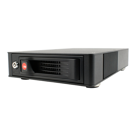
  9. CRU Dataport DE110 Series User manual

CRU Dataport DE110 Series User manual

Rugged, Reliable, Mobile, SecureTM
1-800-260-9800 www.CRU-DataPort.com
DE110 Ultra320 68-Pin Install Guide
Removable Ultra320 Drive Enclosure
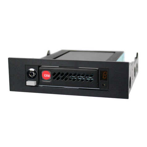
Receiving Frame Motherboard
I/O Connector (J3) - The input/output connector provides a standard
interface for all Ultra320 signals.
DC Power Connector (P1) - A standard 4-pin DC power connector is
used to accept DC power.
Option Pin Connector (W1)
Remote Unit ID Selection: Pins 1-8 of this connector are provided for
SCSI ID selection through a remote ID selector switch. Remote ID selection
requires that the unit ID switch located on the inside of the receiving frame
be set to “0” (onboard ID selection is set with a switch located on the
inside of the receiving frame as shown in Figure 4).
Factory-Installed Jumpers: There are two (2) jumpers factory-installed
on W1 (Pins 9 & 10 and 21 & 22). DO NOT remove these jumpers!
Figure 1: Receiving Frame Motherboard (Rear View)
Installation
1. Carefully insert the drive into the carrier. Slide the drive towards the
Drive Carrier Board, so that the I/O connector on the drive mates
with the connector on the Drive Carrier Board. Turn the drive/carrier
assembly over.
2. Fasten the drive into place with four (4) #6-32 Phillips Flat Head
screws. Some drives may require minor adjustment before securing
into carrier with screws.
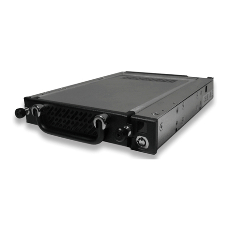
3. Install the provided drive cover.
Spacer Plates (optional)
The DE110 Ultra320 is designed to fit most computer systems with
standard 5.25” peripheral slots. The installation of the spacer plates
(provided) may or may not be necessary.
NOTES: DE110 Ultra320 receiving frames are indicated by their AMBER LED, and the
DE110 Ultra320 carriers are indicated by the Ultra320 logo.
For SCSI Ultra320 operation, the DE110 Ultra320 requires Ultra320 drives, Ultra320 HBA,
and Ultra320-compliant cabling (internal and external).
Due to the fixed connector some hard drives will not fit into the DE110 U320 68-pin carrier.
The DE100 U320 68-pin carrier will work with Seagate and Maxtor hard drives.
Figure 2: Drive Installation Assembly
DC Power
Connector (P1)
68-Pin I/O
Connector (J3) Buzzer
Option Pin
Connector (W1)
Factory
Installed
Jumpers (do
not remove
Remote ID Select
{
GND
ID0
ID1
ID2
ID3
= Pin 1
Rugged, Reliable, Mobile, SecureTM
1-800-260-9800 www.CRU-DataPort.com
Limited Product Warranty
CRU-DataPort (CRU) warrants the Data Express DE110 to be free of sig-
nificant defects in material and workmanship for a period of five years
from the original date of purchase. CRU’s warranty is nontransferable
and is limited to the original purchaser.
Limitation of Liability
The warranties set forth in this agreement replace all other warranties.
CRU expressly disclaims all other warranties, including but not limited
to, the implied warranties of merchantability and fitness for a particular
purpose and non-infringement of third-party rights with respect to
the documentation and hardware. No CRU dealer, agent or employee
is authorized to make any modification, extension, or addition to this
warranty. In no event will CRU or its suppliers be liable for any costs
of procurement of substitute products or services, lost profits, loss of
information or data, computer malfunction, or any other special, indirect,
consequential, or incidental damages arising in any way out of the sale
of, use of, or inability to use any CRU product or service, even if CRU has
been advised of the possibility of such damages. In no case shall CRU’s
liability exceed the actual money paid for the products at issue. CRU
reserves the right to make modifications and additions to this product
without notice or taking on additional liability.
Certification
EMI Standard: FCC Part 15 Class B, CE
EMC Standard: EN55022, EN55024
FCC Certification
This device has been tested and found to comply with the limits
for a Class B digital device, pursuant to Part 15 of the FCC rules.
Operation is subject to the following two conditions:
1. This device may not cause harmful interference.
2. This device must accept any interference receive including
interference that may cause undesired operation.
Register your product at www.CRU-DataPort.com
A7-110-0005 Rev. 3.0
Selecting the Unit ID Number: Use the alignment tool (provided) to
select the ID number of the disk drive.
NOTE: The lock on the Data Express receiving frame functions as
a lock and a DC power switch for the carrier unit. The lock MUST
be engaged (turned counterclockwise) in order to supply power to
the carrier and installed drive unit.
Figure 3: Receiving Frame Unit ID Number and Activity Display
In the event of a fan failure the display window will flash “F” and the
SCSI ID number. For information to replace your fan please contact
CRU-DataPort technical support at 800-260-9800 x 4 or email at Sup-
[email protected].
Figure 4: Unit ID Select Switch Location
Drive Carrier
Guide
Typical Data Express
Receiving Frame
Unit ID Select
Rotating Switch
Carrier Removed from
Receiving Frame
Carrier Installed
(unlocked)
Carrier Installed
(locked)
Fan Failure
The number “2” shown above is for illustration purposes only. It can be any
valid unit ID number. The letter “u” and “F” will appear as illustrated.
Activity
Indicator

This manual suits for next models

1

Other CRU Dataport Enclosure manuals

CRU Dataport Data Express DE75 SAS User manual

CRU Dataport

CRU Dataport Data Express DE75 SAS User manual

CRU Dataport HotDock Secure User manual

CRU Dataport

CRU Dataport HotDock Secure User manual

CRU Dataport DE110 User manual

CRU Dataport

CRU Dataport DE110 User manual

CRU Dataport Data Express DE200 SCSI User manual

CRU Dataport

CRU Dataport Data Express DE200 SCSI User manual

CRU Dataport 2U User manual

CRU Dataport

CRU Dataport 2U User manual

CRU Dataport Data Express DE110 Ultra ATA133 User manual

CRU Dataport

CRU Dataport Data Express DE110 Ultra ATA133 User manual

CRU Dataport RTX 610-IR User manual

CRU Dataport

CRU Dataport RTX 610-IR User manual

CRU Dataport DE200 SCSI User manual

CRU Dataport

CRU Dataport DE200 SCSI User manual

CRU Dataport RTX800-XJ User manual

CRU Dataport

CRU Dataport RTX800-XJ User manual

CRU Dataport ToughTech Duo-QR User manual

CRU Dataport

CRU Dataport ToughTech Duo-QR User manual

CRU Dataport DE50 IDE User manual

CRU Dataport

CRU Dataport DE50 IDE User manual

CRU Dataport TT-Q User manual

CRU Dataport

CRU Dataport TT-Q User manual

CRU Dataport 25 Secure User manual

CRU Dataport

CRU Dataport 25 Secure User manual

CRU Dataport SecureDock User manual

CRU Dataport

CRU Dataport SecureDock User manual
CRU Dataport DE100 ATA 33 User manual

CRU Dataport

CRU Dataport DE100 ATA 33 User manual

CRU Dataport ToughTech Q Operating and maintenance instructions

CRU Dataport

CRU Dataport ToughTech Q Operating and maintenance instructions

CRU Dataport Data Express DX115 SATA User manual

CRU Dataport

CRU Dataport Data Express DX115 SATA User manual

CRU Dataport RTX220-QR User manual

CRU Dataport

CRU Dataport RTX220-QR User manual

CRU Dataport DE75i-SW160 User manual

CRU Dataport

CRU Dataport DE75i-SW160 User manual

CRU Dataport DataPort 5 User manual

CRU Dataport

CRU Dataport DataPort 5 User manual

CRU Dataport RTX430-3QR User manual

CRU Dataport

CRU Dataport RTX430-3QR User manual

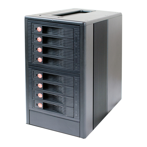
CRU Dataport RTX Secure 410-SJ User manual
CRU Dataport

CRU Dataport RTX Secure 410-SJ User manual

CRU Dataport DE100 Series User manual

CRU Dataport

CRU Dataport DE100 Series User manual

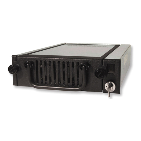
CRU Dataport Multi-Lane DataPAK User manual
CRU Dataport

CRU Dataport Multi-Lane DataPAK User manual

Popular Enclosure manuals by other brands
Panamax MIW-POWER-PRO-PFP installation instructions

Panamax

Panamax MIW-POWER-PRO-PFP installation instructions

Fantec DB-R35DUE user manual

Fantec

Fantec DB-R35DUE user manual

Encore ENUHDE-IFP user manual

Encore

Encore ENUHDE-IFP user manual

D.A.S. sub-18HA user manual

D.A.S.

D.A.S. sub-18HA user manual

Conceptronic HDE02B Multi Language Quick Guide

Conceptronic

Conceptronic HDE02B Multi Language Quick Guide

ICC ICRESDP28K quick start guide

ICC

ICC ICRESDP28K quick start guide

Minebea Intec MP 90/04 installation manual

Minebea Intec

Minebea Intec MP 90/04 installation manual

Toa SB-46S instruction manual

Toa

Toa SB-46S instruction manual

BEL cinch ModICE SE Series Assembly instructions

BEL

BEL cinch ModICE SE Series Assembly instructions

DMP Electronics 341 Installation sheet

DMP Electronics

DMP Electronics 341 Installation sheet

Addonics Technologies ZSNESA user guide

Addonics Technologies

Addonics Technologies ZSNESA user guide

EFX FDMUS05U installation instructions

EFX

EFX FDMUS05U installation instructions

Leviton LP8 Series installation instructions

Leviton

Leviton LP8 Series installation instructions

ETI ECM36PO MEDIA-MOD Mounting instructions

ETI

ETI ECM36PO MEDIA-MOD Mounting instructions

PCB Piezotronics IMI SENSORS PCB-691A50/04 Installation and operating manual

PCB Piezotronics

PCB Piezotronics IMI SENSORS PCB-691A50/04 Installation and operating manual

Kinedo Kinespace 2P installation instructions

Kinedo

Kinedo Kinespace 2P installation instructions

Antec Veris Fusion Remote Max Parts Breakdown

Antec

Antec Veris Fusion Remote Max Parts Breakdown

Peavey 1522 HC Specifications

Peavey

Peavey 1522 HC Specifications

manuals.online logo
manuals.online logoBrands
  • About & Mission
  • Contact us
  • Privacy Policy
  • Terms and Conditions

Copyright 2025 Manuals.Online. All Rights Reserved.