SCHUMANN Momo User manual

Instructions for use.
momo tricycle. The tricycle as therapy aid.
momo tricycle.

Many thanks.
Dear Customer
At this point we would like to thank you for placing your trust in our company and
for purchasing our product. We ask you to read through the Instructions for use carefully
prior to initial commissioning of the product, and to observe them. Please note that gui-
delines and representations in these Instructions for use may deviate from your product
due to diering equipment. We reserve the right to make technical modifications.
Important information!
Ensure that these Instructions for use remain with the product.
Your schuchmann Team

2. Product description.
03 Contents.
1. Preparation. .................................................................................. 05
1.1 Delivery............................................................................................................................05
1.2 Safety measures prior to use ..............................................................................05
1.3 Safe disposal...............................................................................................................05
1.3.1 Packaging...........................................................................................................05
1.3.2 Product................................................................................................................05
1.4 Where to store the Instructions for use..........................................................05
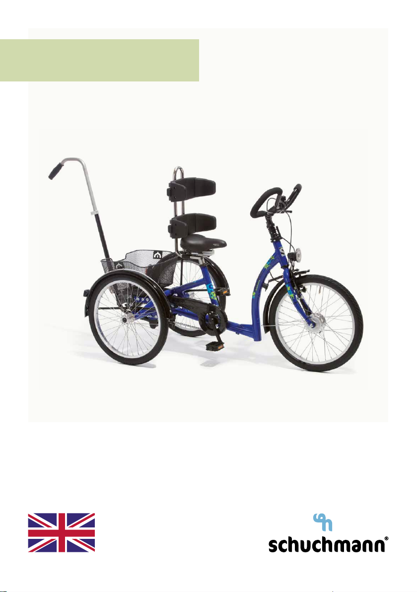
2. Product description. ...................................................................... 06
2.1 General information.................................................................................................06
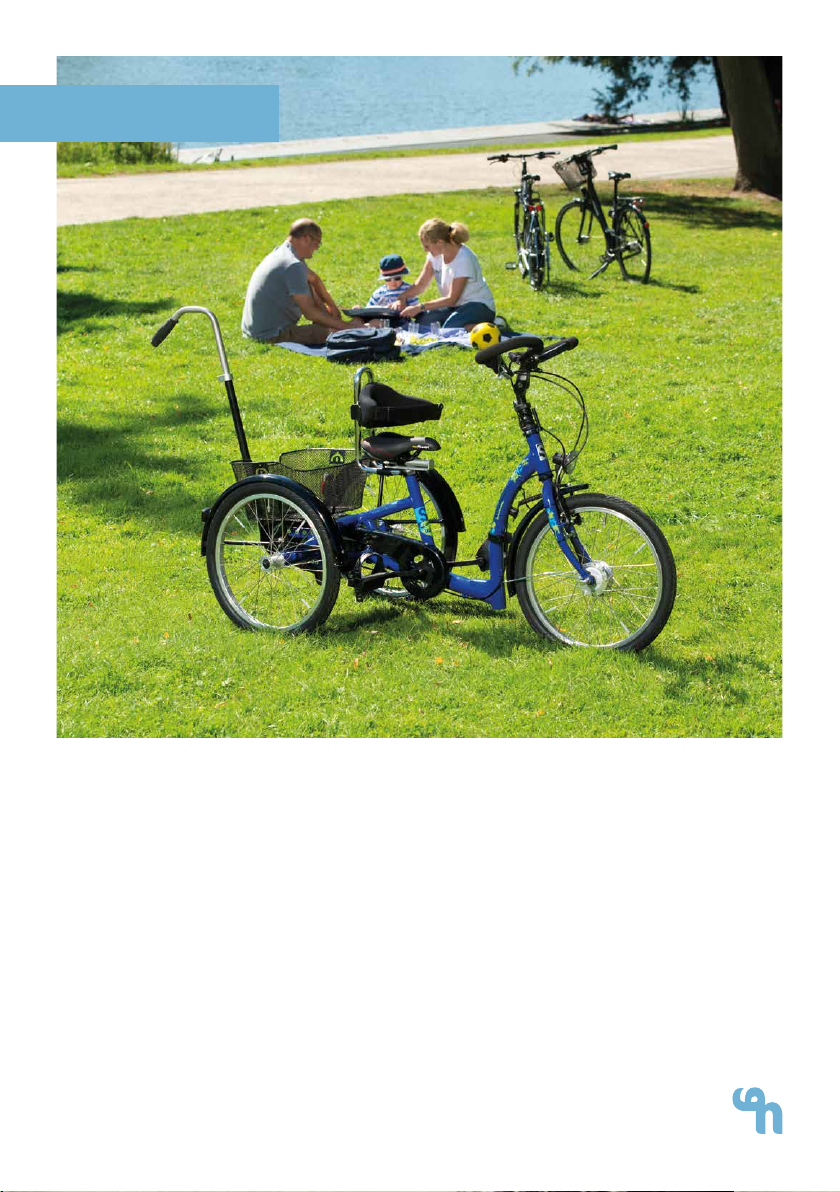
2.2 Handling and transport........................................................................................06
2.3 Application areas, use according to the intended purpose .............06
2.3.1 Indications .........................................................................................................06
2.3.2 Contraindications ........................................................................................07
2.4 Use not in accordance with the intended purpose / warning gui-
delines............................................................................................................................07
2.5 Equipment in accordance with StVZO..........................................................08
2.6 Equipment for basic model.................................................................................09
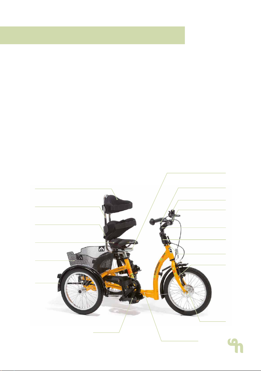
2.7 Product overview......................................................................................................09
2.8 Overview of equipment / accessories ...........................................................10
2.9 Drive possibilities........................................................................................................ 15
2.10 The initial riding attempts................................................................................... 16
3. Settings. ....................................................................................... 17
3.1 Presettings ..................................................................................................................... 17
3.1.1 Handlebar adjustment.................................................................................. 17
3.1.2 Saddle adjustment ........................................................................................18
3.2 Brakes.............................................................................................................................. 19
3.2.1 Parking brake..................................................................................................... 19
3.2.2 Round handlebars with brake lever ring............................................20
3.2.3 Round handlebars with brake function..............................................20
3.2.4 Drum brake in front wheel.........................................................................20
3.2.5 Backpedal brake...........................................................................................20
3.3 Tyres and hoses.......................................................................................................... 21
3.4 Light system / dynamo.......................................................................................... 21
4. Accessories. .................................................................................. 22
4.1 Dynamic back and pelvic guide pelotte pads ......................................... 22
4.1.1 Width adjustable back and pelvic guide pelotte pads ............. 22
4.2 Headrest....................................................................................................................... 22
4.3 Push bar........................................................................................................................ 23
4.4 Parking brake for accompanying escorts................................................... 23
4.5 Steering for accompanying escorts............................................................... 23
4.6 Handlebar lock limiter ........................................................................................... 24
4.7 Holding bracket with mount............................................................................... 24
4.8 Universal adapter .................................................................................................... 25
4.9 Crank shortener (continuously adjustable) ................................................. 25

04 Contents.
4.10 Crank shortener...................................................................................................... 25
4.11 Special crank for knee contracture................................................................ 26
4.12 Removable axle stabilisers................................................................................ 26
4.13 Exercise bike pedals.............................................................................................. 26
4.14 Foot positioning pedals.......................................................................................27
4.15 Foot pans....................................................................................................................27
4.16 Foot pans with leg guidance........................................................................... 28
4.17 Foot pans with dynamic leg guidance....................................................... 28
4.18 Chest strap................................................................................................................ 29
4.19 Positioning vest........................................................................................................ 29
4.20 Groin harness, T-shaped...................................................................................30
4.21 4-point pelvic harness.........................................................................................30
4.22 Hand positioning aid...........................................................................................30
5. Cleaning and servicing. ................................................................. 31
5.1 Cleaning and disinfecting ..................................................................................... 31
5.1.1 Cleaning ............................................................................................................... 31
5.1.2 Disinfection......................................................................................................... 31
5.1.3 Chain maintenance ...................................................................................... 32
5.2 Servicing / controls ................................................................................................. 32
5.3 Maintenance .............................................................................................................. 32
5.3.1 Maintenance specifications ..................................................................... 33
5.3.2 Maintenance plan......................................................................................... 33
5.4 Repairs...........................................................................................................................34
5.5 Controls.........................................................................................................................34
5.6 Storage..........................................................................................................................34
5.7 Spare parts..................................................................................................................34
5.8 Duration of use and re-use................................................................................. 35
6. Technical data. .............................................................................. 36
6.1 Dimensions ................................................................................................................... 36
6.2 Torque specifications............................................................................................. 36
6.3 Tyre pressure............................................................................................................... 37
7. Guarantee. .................................................................................... 37
8. Identication. ............................................................................... 38
8.1 EU Declaration of Conformity............................................................................. 38
8.2 Serial number / date of manufacture...........................................................40
8.3 Product version .........................................................................................................40
8.4 Issue of the document ..........................................................................................40
8.5 Name and address of the manufacturer, specialist dealer sup-
plying the product...................................................................................................40
04

05 1. Preparation.
1.1 Delivery
On receiving the product, please check it for completeness, lack of faults
and any transport damage. Inspect the goods in the presence of your
forwarder. Should transport damage have occurred, please arrange for
an inventory (determination of the faults) to be made in the presence of
the forwarder. Please send a complaint in writing to the specialist dealer
responsible.
1.2 Safety measures prior to use
The correct use of the product requires a detailed and careful instruction
of the user or the accompanying person. We ask you to read through the
Instructions for use carefully prior to initial commissioning of the product,
and to observe them. It is possible that product parts that get in contact
with the skin may heat up in the sun. Cover these areas or protect the de-
vice from direct sunlight.
1.3 Safe disposal
In order to preserve and protect the environment, to prevent environmental
pollution and to improve the recycling of raw materials, please note the
disposal instructions in points 1.3.1 and 1.3.2.
1.3.1 Packaging
The packaging of the product should be kept for any future transport that
might be required. Should you have to return the product for repairs or in
case of a guarantee claim, please if possible use the original box so that
the product is optimally packaged. Otherwise, separate the packaging
materials for recycling according to their classification.
Do not leave packaging materials unattended, as they are a possible source of
danger.
1.3.2 Product
Attheendoftheproductlifecycle,recycletherawmaterialsusedintheproduct
according to their nature (see material information under point 2.1).
1.4 Where to store the Instructions for use
Please store these Instructions for use carefully and ensure that these Inst-
ructions for use remain with the product in case of re-use. Should you lose
the instructions, you can always download an updated version at www.
schuchmann.de .

06 2. Product description.
2.1 General information
All base frames are made of aluminium, which is non-corroding and pow-
der-coated. All other materials used are protected against corrosion th-
rough the use of stainless steel, aluminium or plastic. All important parts,
such as the saddle, handlebars or also the pedals, can be individually ad-
apted to the individual requirements. Thanks to special accessories, users
can be positioned e.g. at the torso or in the calf area / foot area. The tricy-
cles generally have a brake hub / backpedal hub brake on the rear wheel
(except for those with a rigid sprocket) and an air pressure-independent
parking brake on the front wheel.
2.2 Handling and transport
The momo tricycle. is not intended for carrying since it is equipped with
wheels. Should you have to carry the equipment due to obstacles, ensu-
re that all moving parts are tightened. Then two people should position
themselves next to the tricycle, grip it on the left and right of the frame
and carry it to the required location. To transport the tricycle, reduce all
adjustments to their most compact size (saddle height, handlebar height,
remove accessories etc.).
2.3 Application areas, use according to the intended purpose
The momo tricycle. is a medical product of risk class 1 and was designed
for children, youths and adults for outdoors. This tricycle permits users with
disabilities (see indications) to move independently. The physiotherapeutic
treatment is supported and the support and balance reactions as well as
movement coordination are trained. Any other use or use over and abo-
ve this purpose shall be considered not in accordance with the intended
purpose.
2.3.1 Indications
The momo tricycle. is suited for users with neuromuscular disorders (e.g.
cerebral palsy, muscular dystrophy), who cannot use standard bicycles or
vehicles, not even with commercial support wheels, due to their disabilities.
To ensure mobility in outdoor areas and participation in social life (integra-
tion in a group of persons of the same age) and/or to improve the support
and balance reaction/movement coordination within the scope of physio-
therapeutic treatment (regular measures of physical therapy)

07 2. Product description.
2.3.2 Contraindications
In general, the indication should be accompanied by a doctor/orthopae-
dist. It should therefore be clarified prior to procurement whether contrain-
dications exist for the patient. Any danger to the user or others through the
use of a tricycle should be excluded. In general, any type of pain repre-
sents a contraindication.
2.4 Use not in accordance with the intended purpose / warning guidelines
• Correct usage of the product requires precise and careful training of the
accompanying person.
• Replace bent handlebars and handlebar stems immediately!
Breakage may occur in the event of continued use or repairs.
• The vehicle may only be used on stable and flat ground.
• Please observe the "Technical data" in these instructions for use for the
maximum permitted patient weight.
• Always wear light-coloured and distinctive clothing!
• Always be ready to brake, in particular in steep terrain and sections
which are not easy to assess!
• Show consideration for other people who are walking or hiking!
• Do not hang loads on the handlebars; this compromises the travel
safety.
• Test the fastenings for the pedal cranks, pedals and, if applicable,
the wheels regularly
• For your own safety, we recommend that you always use your vehicle
with a helmet. Please ensure in particular that the helmet is of good
quality. It should accord at least with the legal regulations or
recommendations (standard: EN 1078 or ANS)!
• Check that the brakes, lights and bell function properly prior to each
journey!
• Ensure that your vehicle accords with the legal requirements!
• Only ride if the bicycle is in proper condition!
• Do not use headphones so that you can remain aware of warning
sounds.
• If a push rod is mounted, it must only be used to guide the vehicle. The
push rod is NOT suited for relocating the bicycle or for lifting or tilting!
• In wet conditions, the braking distance of your tricycle will become
longer. Therefore, always ensure that your speed remains such
that you can stop at any time.
• The tricycle is not suitable for carrying a second person. The
consequences arising from such use, which is not in accordance with
the intended purpose, shall not fall within the scope of responsibility of
the manufacturer.

08 2. Product description.
• The tricycle basket may only bear loads of up to 20 kg.
• When adjusting the tricycle there is the risk of trapping or crushing limbs.
• Users who have diculty reading must have someone read these
Instructions for use aloud so that they understand how to use
the product.
2.5 Equipment in accordance with StVZO
For roadworthy tricycles, the following components are specified in accor-
dance with the German Road Trac Regulations:
• Two brakes functioning independently of one another
• A bicycle bell with a clear ring
• Headlamps, rear lamp with reflectors, large-area reflectors, pedal
reflectors, 2 yellow spoke reflectors or white reflecting rings on each
wheel, and front reflectors in the design tested for the construction type.
• A bicycle trailer may only be used on bicycles with a sturdy frame and
fork construction. Also important are strong bicycle brakes at the front
and rear. Users must remember that the riding characteristics of the
loaded trailer change substantially in comparison to operation of the
bicycle on its own.

09 2. Product description.
2.6 Equipment for basic model
• Aluminium frame with extra-low
access point
• Rim brake with separate parking
brake
• Angle adjustable handlebar stem
• Light system acc. German Road
Trac Regulations (24" - 26")
• Handlebar damper for stabilisati-
on when moving straight on
• Drum brake in front wheel
(16" - 26")
• Mudguards on all wheels (no
mudguard at rear for 12")
• Basket
Saddle
Basket
Fender
guard
Dynamic
Back pelotte pad
Holding bracket
Dynamic
Pelvic pelotte pad Angle adjustable
handlebar stem
Handlebar lock
limiter
Drum
brake
Pedal Aluminium frame
with extra
low access point
Lever for parking brake
Handlebars
V-brake
Bell
Brake lever
T-saddle post
2.7 Product overview
The Fig. below is intended to show you the designation of the most im-
portant components as well as the terms which you will find in these Inst-
ructions for use.

10 2. Product description.
2.8 Overview of equipment / accessories
Saddle posts
Art. No. Saddle post
3701004 Standard saddle post Size 1 for 12"
3702 004 Standard saddle post Size 2 for 16"
3703004 Standard saddle post Size 3 for 20" - 26"
Art. No. T-saddle post
3701005 T-saddle post Size 1 for 12"
3702 005 T-saddle post Size 2 for 16" + 20"
3703005 T-saddle post Size 3 for 24" + 26"
Saddle
Art. No. Saddle Width Length
3701001 Standard saddle Size 1 15 cm 21 cm
3702 001 Standard saddle Size 2 15 cm 24 cm
3703001 Standard saddle Size 3 18 cm 26 cm
Art. No. Saddle Rear width Front width Length
3701024 Gel saddle Size 1 19 cm 4 cm 24 cm
3702 024 Gel saddle Size 2 24 cm 7 cm 27 cm
Art. No. Saddle Rear width Front width Rear length Length
total
3701003 Saddle seat with ischium
depressions Size 1 20.5 cm 4 cm 9.5 cm 14.5 cm
3702 003 Saddle seat with ischium
depressions Size 2 24 cm 4 cm 9.5 cm 14.5 cm
Art. No. Saddle Rear width Width in
centre Front width Length
3700 010
Unicycle saddle –
Banana-shaped (Step
length increases by
2 cm)
11 cm 6 cm 8 cm 25 cm
Art. No. Saddle Rear width Front width Rear length Length
total
3700 023
Moped saddle (Inside
leg length increases
by 2 cm)
26 cm 9.5 cm 12 cm 25 cm
Holding bracket
Art. No. Holding bracket with mount Max. height* Depth
3701007 Holder bracket Size 1 20 cm 12 cm
3702 007 Holder bracket Size 2 30 cm 12 cm
3703007 Holder bracket Size 3 37 cm 12 cm
3704 007 Holder bracket Size 4 53 cm 12 cm
3709 007 Holder bracket, customer-made ___ cm ___ cm
3702 055 Universal bracket – for harnesses when not using
pelotte pads (width = 27.5 cm)
* Max. height: measured on a standard saddle up to the top edge of the back pelotte pad

11 2. Product description.
Foot pans
Art. No.
Foot pans
with leg
guidance
Min.
width at
front
Max.
Front
width
Min.
width at
rear
Max.
Rear
width
Length
Min.
height
of leg
guidance
Max.
height
Leg gui-
dance
3701018 Size 1 8.7 cm 10.4 cm 5.7 cm 7.4 cm 17.4 cm 15 cm 18.5 cm
3702 018 Size 2 9.5 cm 12 cm 6.7 cm 9.2 cm 20.1 cm 18 cm 22 cm
3703018 Size 3 11.5 cm 14 cm 8.1 cm 10.6 cm 23.8 cm 21 cm 26 cm
3704 018 Size 4 11.5 cm 14 cm 8.1 cm 10.6 cm 23.8 cm 28 cm 36 cm
Art. No. Foot pans
Min.
width at
front
Max.
width at
front
Min.
width at
rear
Max.
width at
rear
Length
3701017 Foot pans Size 1 8.7 cm 10.4 cm 5.7 cm 7.4 cm 17.4 cm
3702 017 Foot pans Size 2 9.5 cm 12 cm 6.7 cm 9.2 cm 20.1 cm
3703017 Foot pans Size 3 11.5 cm 14 cm 8.1 cm 10.6 cm 23.8 cm
Handlebars
Art. No. Classic handlebars – black Width
3701011 Classic handlebars for 12" 47 cm
3702 011 Classic handlebars for 16" 50 cm
3703011 Classic handlebars for 20" 58 cm
3704 011 Classic handlebars for 24"-26" 61 cm
Art. No. Touring handlebars Width Depth
3701012 Touring handlebars Size 1 55 cm 17 cm
3702 012 Touring handlebars Size 2 58 cm 17 cm
Art. No. Round handlebars Width Depth
3701013 Round handlebars Size 1 40 cm 17 cm
3702 013 Round handlebars Size 2 43 cm 25 cm
Art. No. Multifunctional handlebars – suitable for 20" – 26" Width Depth
3702 014 Multifunctional handlebars 61.5 cm 16.5 cm
Art. No. Handlebar lock limiter – adjustable up to direction determination
3701006 Handlebar lock limiter Size 1 for 12"
3703006 Handlebar lock limiter Size 2 for 16" - 26"
Art. No. Handlebar extension Length
3701022 Handlebar extension Size 1 for 12" 10 cm
3702 022 Handlebar extension Size 2 for 16" - 26" 10 cm
Headrest
Art. No. Headrest Width Height
3701029 Headrest Size 1 20 cm 15 cm
3702 029 Headrest Size 2 23 cm 18 cm

12 2. Product description.
Pedals
Art. No. Pedals Depth
3700 013 Foot positioning pedals – with bike toe clips and compensation weights 13 cm
Art. No. Pedals Width
3700 014 Exercise bike pedals 12 cm
Back pelotte pads
Art. No. Dynamic back pelotte pads – padded with strap and mount Width
3701008 Dynamic back pelotte pad Size 1 20 - 30 cm
3702 008 Dynamic back pelotte pad Size 2 25 - 35 cm
3703008 Dynamic back pelotte pad Size 3 30 - 40 cm
Art. No. Width adjustable back pelotte pad - padded, including mount Width
3701025 Width adjustable back pelotte pad Size 1 20 - 28 cm
3702 025 Width adjustable back pelotte pad Size 2 25 - 33 cm
3703025 Width adjustable back pelotte pad Size 3 30 - 36 cm
Pelvic supports
Art. No. Dynamic pelvic guidance pelotte pad – padded, with strap and
mount Width
3701009 Dynamic pelvic guidance pelotte pad Size 1 20 - 30 cm
3702 009 Dynamic pelvic guidance pelotte pad Size 2 25 - 35 cm
3703009 Dynamic pelvic guidance pelotte pad Size 3 30 - 40 cm
Art. No. Width adjustable back guidance pelotte pad - padded, including
mount Width
3701026 Width adjustable pelvic guidance pelotte pad Size 1 20 - 28 cm
3702 026 Width adjustable pelvic guidance pelotte pad Size 2 25 - 33 cm
3703026 Width adjustable pelvic guidance pelotte pad Size 3 30 - 36 cm
Foot pans
Art. No.
Foot
pans with
dynamic leg
guidance
Min.
width at
front
Max.
width at
front
Min.
width at
rear
Max.
width at
rear
Length
Min.
height
of leg
guidance
Max.
height
Leg gui-
dance
3701035 Size 1 8.7 cm 10.4 cm 5.7 cm 7.4 cm 17.4 cm 15 cm 18.5 cm
3702 035 Size 2 9.5 cm 12 cm 6.7 cm 9.2 cm 20.1 cm 18 cm 22 cm
3703035 Size 3 12 cm 15 cm 8.8 cm 11.8 cm 24 cm 20.5 cm 25.5 cm

13 2. Product description.
Positioning
Art. No. Hand positioning - for all handlebars Front width
3700 054 Hand positioning size 0 8.5 cm
3701054 Hand positioning size 1 10 cm
3702 054 Hand positioning size 2 12 cm
3703054 Hand positioning size 3 14 cm
Art. No. Chest strap – for the width adjustable back pelotte pad Width Length
3701050 Chest strap Size 1 5 cm 18.5 cm
3702 050 Chest strap Size 2 6.5 cm 25.5 cm
3703050 Chest strap Size 3 7 cm 30.5 cm
Art. No. Positioning vest – for the width
adjustable back pelotte pad
Inside
width
Total
width
Side
height Total height
3701051 Positioning vest size 1 8 cm 25 cm 10 cm 28 cm
3702 051 Positioning vest size 2 9 cm 30 cm 12 cm 30 cm
3703051 Positioning vest size 3 12 cm 34 cm 16 cm 35 cm
Art. No.
Groin strap, T-shaped – for the
width adjustable pelvic pelotte
pad
Width
Seat
surface
Front
width
Length
Seat
surface
Total length
3701052 Groin harness, T-shaped Size 1 24 cm 23 cm 15 cm 32 cm
3702 052 Groin harness, T-shaped Size 2 26 cm 26 cm 17 cm 34 cm
3703052 Groin harness, T-shaped Size 3 28 cm 28 cm 19 cm 38 cm
Art. No.
4-point pelvic harness - for the
width adjustable pelvic pelotte
pad
Width
Exterior
parts
Width
Centre
section
Length
Exterior
parts
Length
Centre
section
3701053 4-point pelvic harness Size 1 7 cm 7 cm 12 cm 12 cm
3702 053 4-point pelvic harness Size 2 9 cm 8.5 cm 13 cm 14 cm
3703053 4-point pelvic harness Size 3 11.5 cm 11 cm 15 cm 16 cm
Handlebars
Art. No. Push bar - height adjustable, removable and equipped with an integrated antiro-
tation lock
3700 011 Push bar
Art. No. Parking brake for accompanying escorts - only usable in connection with push bar
3700 012 Parking brake for accompanying escorts
Art. No. Steering for accompanying escorts using steering linkage including handlebar lock
limiter (can only be used in connection with push bar)
3701010 Steering for accompanying escorts for 12"
3702 010 Steering for accompanying escorts for 16"
3703010 Steering for accompanying escorts for 20"
3704 010 Steering for accompanying escorts for 24"
3705 010 Steering for accompanying escorts for 26"

14 2. Product description.
Axle stabiliser
Art. No. for
3703023
Removable axle stabilisers – not possible with switching drives
20“
3704 023 24“
3705 023 26“
Basket
Art. No. Basket
3801019 Basket for 12" + 16"
3803019 Basket for 20" + 24"
3805 019 Basket for 26"
Light system
Art. No. Light system
3703021 Retrofitting of the lights system for 12" side dynamos and reflectors acc. German
Road Trac Regulations
3702 021 Retrofitting of a light system for 16“ + 20“ with side dynamos and reflectors
acc. German Road Trac Act Regulations
3701021 Retrofitting of a lights system for 16" + 20" with hub dynamo and reflectors acc.
StVZO (German Road Trac Act Regulations)
3704 021 Lights system with hub dynamo for 24" + 26"
Handlebar brake
Art. No. Handlebar brake for
3701028 Round handlebars with brake lever ring Size 1
3702 028 Size 2
3701031 Round handlebars with brake function
The actuation of the braking function takes place by simply
pressing down the round handlebars
Size 1
3702 031 Size 2

15 2. Product description.
2.9 Drive possibilities
The momo tricycle. can be equipped
with the following drives:
Rigid sprocket
During active pedaling, the rigid spro-
cket supports the user in overcoming
the "dead"/apex point of the crank.
A passive user is assisted in pedalling
constantly; in addition it permits travel
forwards or backwards.
Changeover from rigid sprocket to neutral hub
In addition to the functions of the rigid sprocket, the drive can be uncou-
pled and thus the passive pedalling can be interrupted, for example for
transfer distances.
Freewheel brake hub (with backpedal brake)
The freewheel brake hub allows the user to stop and start pedalling as
they wish. They can brake by pedalling backwards.
Extra-light transmission
An extra-light transmission can be selected for all the above-mentioned
types of drive. Here a larger pinion on the rear axle permits improved force
transmission and thus makes it easier for the user to start pedalling.
Transfer between the rigid sprocket, idling hub and 7 gear freewheel brake
hub with reverse option
This option combines the functions of the above-mentioned drives. Using
a switch lever (A), it is possible to select between a rigid sprocket, idling hub
and the 7 gear freewheel brake hub with reverse option. To do this, pull the
level (A) out of the recess and allow
it to engage in the required position
in order to select between the die-
rent drive versions. In the left-hand
recess, the rigid sprocket, in the cen-
tral recess the idling hub and in the
right-hand recess the 7-gear free-
wheel brake hub with reverse option
can be activated.
A

16 2. Product description.
3 or 7-gear freewheel brake hub (with backpedal brake)
Using the 3 or 7-gear freewheel brake hub, the user can stop and start
pedalling at will. They can brake by pedalling backwards. The user-friendly
3 or 7-gear hub gear system permits switching of gears when the tricycle
is at a standstill. Switching takes place using the twist grip shifter on the
handlebars.
3 or 7-gear neutral hub (without backpedal brake)
Using the 3 or 7-gear neutral hub, the user can stop and start pedalling at
will. They can also bring the pedals into the optimum position to start using
the neutral gear. The user-friendly 3 or 7-gear hub gear system is suitable
for any terrain and also permits switching of gears when the bicycle is at
a standstill. Switching takes place using the twist grip shifter on the hand-
lebars.
3 or 7-gear freewheel brake hub with reverse option
Using the 3 or 7-gear freewheel brake hub, the user can stop and start
pedalling at will. In addition, they can ride backwards. The user-friendly
3 or 7-gear hub gear system permits switching of gears when the tricycle
is at a standstill. Switching takes place using the twist grip shifter on the
handlebars.
7-gear freewheel brake with wheel brake (without backpedal brake)
In the 7-gear freewheel hub with wheel brake forward, the movement can
be interrupted as desired and be converted in free backwards pedaling in
further forward drive. The user-friendly 7-gear hub gear system is suitable
for any terrain and also permits switching of gears when the bicycle is at
a standstill. Switching takes place using the twist grip shifter on the hand-
lebars.
2.10 The initial riding attempts
Please remember that, prior to setting o on your own, you must first
practice with an accompanying escort in order to learn how to deal with
riding around curves on the tricycle, as this is where the risk of accidents
is greatest. Always ride around curves as slowly as possible. Please also
remember that the widest part of your tricycle is behind you. Therefore,
practice using appropriate obstacles so that you learn to estimate the
width of your tricycle better.

17 3. Settings.
Settings and adjustments to the product or accessories may only be made
by people who have been given the necessary instructions by a medical
product advisor. Please ensure that none of the user's extremities are in the
respective area when making adjustments of any kind to minimise the risk of
injury.
3.1 Presettings
The momo tricycle. is supplied completely as-
sembled. Prior to initial use, however, the fol-
lowing pre-settings must be made.
3.1.1 Handlebar adjustment
You can find our scope of delivery for hand-
lebars on page 11 of these Instructions for use.
Height of handlebars
To adjust the height of the handlebars, remove
the protective cap from the hexagon socket
(A), loosen the hexagon socket (A) and adjust
the stem (B) to the required height. By tap-
ping the head of the hexagon socket (E) light-
ly with a hammer, the stem in the fork steerer
will loosen. Then re-tighten the hexagon so-
cket.
Ensure that the marking for the minimum inser-
tion depth (C) remains on the stem in the fork
steerer and therefore cannot be seen.
Handlebar adjustment
To adjust the handlebar position, loosen the
clamping screws (D), bring the handlebars
into the required position and then firmly
re-tighten the clamping screws (D). To change the tilt angle on the stem,
please loosen the clamping screw (F). The steerer factory setting is 20°. In
this way you can change the distance between the saddle and the hand-
lebars, and adjust the required handle height. Then firmly re-tighten the
screws again.
After each adjustment, please retighten all screw connections!
After adjustment of the handlebars, there must still be no tension placed on the
brake cables. If necessary, extend the cables!
F
D
A
D
B
E
C

18 3. Settings.
3.1.2 Saddle adjustment
You can find our selection of saddle forms on
page 10 of these Instructions for use.
Saddle height
The height of the saddle can be adjus-
ted on the frame saddle tube (A) by pulling
the saddle post in or out. In order to ad-
just the height, please loosen the clamp
(B) and bring the saddle into the requi-
red height. Align the saddle and tigh-
ten the clamp (B) so tightly that the saddle support no longer twists.
Thesaddleheightistobere-setbasedontheinseamlength.Hereanycontrac-
turesofthekneesmustbetakenintoconsideration.Thesaddleheightshouldbe
inspected when the user is sitting on the saddle. The leg extension should
not be 0°. In the upper position of the pedal, the knee flexion should not be
more than 90°. Should it not be possible to achieved this setting through
the saddle height, it is possible to undertake further settings through crank
shortening (see point 4.9 - 4.11).
Adjusting the saddle horizontally
Every saddle (except for the unicycle saddle)
can be minimally adjusted horizontally. To do
this, loosen the nuts (D) with a size 13 wrench
and push the caliper block (C) forwards or
backwards on the seat stays.
Adjusting the saddle with t-saddle post ho-
rizontally
In order to check the horizontal saddle positi-
on, turn the pedal crank horizontally forwards
and put the foot (while the rider is sitting on
the saddle) onto the pedal. Once the lower
leg is vertical, the saddle position is correct.
You can also loosen the two nuts (D) under
the saddle using a size 13 wrench, push the
saddle to the rear or forwards and re-tighten
the nuts.
During adjustment, the saddle post may not be
pulled out over the respective marking, as in this case sufcient clamping can-
not be guaranteed. The markings are in part designed differently.
After each adjustment, please retighten all screw connections!
C
B
A
D

19 3. Settings.
3.2 Brakes
For the momo tricycle. dierent brakes are available, depending on the
user's individual requirements.
3.2.1 Parking brake
The parking brake supports the use
when climbing on and o the tricycle
and secures it against inadvertently
rolling away. To activate the parking
brake, press the lever (A) on the hand-
lebar stem (B) downwards. To release
the parking brake, push the lever up
again.
Always ensure that the brake or the brake
blocks function correctly and have been
adjusted (see below).
Adjustment of the parking brake or brake blocks
Ensure that the braking function im-
mediately takes eect on actuation
of the parking brake lever, taking the
necessary backlash into account.
Due to "settling" of the Bowden cab-
les and the natural wear on the bra-
ke blocks, it is necessary to reset the
brake or replace the brake blocks af-
ter a certain amount of time. Each gap
between the rim and the brake lining
should not be larger than 1.5 mm. To
do this, loosen the clamping screw (C), press the brake blocks together by
hand, pull the Bowden cable taut and then re-tighten the clamping screw.
If the brake blocks are not accurately aligned with the rim edge (D), you
must readjust them accordingly. In order to change the alignment of the
brake blocks, loosen the screws (E). Leave this work to your specialist dealer
in case of any uncertainty.
After each adjustment of the cantilever (V) brake, carry out a brake test. The
brake blocks may only be replaced by ones in an identical design. Observe the
manufacture name or marking and the type designation. New brake blocks
do not achieve the required braking effect until they have been used multiple
times.
C
D
E
A
B

20 3. Settings.
3.2.2 Round handlebars with brake lever ring
Braking with round handlebars with brake le-
ver ring is done by gently pushing down the
ring (A) and is therefore suitable for users with
limited strength in arms and hands who re-
quire the round handlebars as support point
at the same time. The brake lever ring is cou-
pled with the rim brake.
3.2.3 Round handlebars with brake function
The braking function is triggered by simply
pressing the round handlebars (B) down-
wards. The round handlebars with braking
function is suitable for users with limited
strength in arms and hands.
3.2.4 Drum brake in front wheel
The brake lever for actuation of the drum
brake is located on the right-hand side
of the handlebars. If available, plea-
se use the front wheel drum brake always
only in connection with the backpedal brake
while riding the bicycle.
The braking effect can be reduced if the brakes
are used frequently. Therefore ensure to regular-
ly re-adjust the Bowden cable of the brake when
you notice a loss in braking power (see Point
3.2.1)
3.2.5 Backpedal brake
The backpedal brake is actuated by pedaling backwards. The drive op-
tions of the freewheel brake hub and the 3 or 7-gear freewheel brake hub
feature a backpedal brake.
The backpedal brake is only functional when the chain sits correctly! If the chain
jumps off, it is not possible to brake using the backpedal brake!
The rear wheel may block in case of strong braking procedures. Risk of crashes!
During long downhill runs, it is essential that you use the front and rear brakes
in order to avoid overheating of the rear hub brake. This may lead to brake mal-
functions!
A
b
Table of contents
Popular Bicycle manuals by other brands

Canyon
Canyon Roadlite:ON CF R084 quick start guide

Blix
Blix Vika + Assembly guide

Lectric eBikes
Lectric eBikes XPeak owner's manual

Prodeco Technologies
Prodeco Technologies G Storm user guide

Kettler
Kettler Quadriga Comp Belt Translation of original operating instructions

HP Velotechnik
HP Velotechnik Gekko fx 20 Operating manual and service instructions