RBSM Pluto R User manual

1
RBSM
Burlington, Ontario
Toll free customer service line: 1 844 202-3572
Electric bicycle Manual
Pluto R Pluto C2

2
You must read this manual carefully to
familiarize yourself with your vehicle. The
expert treatment, in addition to the regular
care and maintenance of the vehicle serves
to maintain its value.
For reasons of safety, please also pay
attention to the information about
modifications, accessories and spare parts.
Provide the owner's manual with the sale of
your vehicle.
The factory is constantly working on the
further development of all models. Please
understand that changes to the scope of
delivery in terms of shape, equipment and
technology are therefore possible at any
time. Therefore no claims can be derived
from the information, illustrations and
descriptions of these operating instructions.
All texts, illustrations and instructions of this
manual are to be found on the information
stand at the time of printing. The information
contained in this manual is valid on the
closing date. Errors and omissions
excepted.
Reproduction, duplication or translation,
even in part, is not permitted without
permission. All rights under the copyright
law are expressly reserved. Changes
reserved.
Used symbols
Important notes for your safety are specially
marked. Be sure to follow these instructions
to avoid personal injury and damage to the
unit:
WARNING
Warns of dangers to your health and
indicates possible injury risks.
DANGER
Indicates a potential hazard to the device or
other objects.
NOTE
Highlights tips and information for you.

3
Content
Bicycle side view right …………………..4
Handlebar fittings …………………….…5
Display ……..………..………………....6-15
Seat position ………..………………….16
Adjust saddle …………..………………17
Adjust the handlebars…………….….. 18
Safety instructions for the charger …..19
Charger functions………..……………. 20
Safety information for the battery..…….21
Handling of the battery and charger…..22
Charge the battery ……………………..23
Tire pressure ……………….……….…..24
Riding ………………………….……24-25
Support lever...………………………….25
Range….……………………………….. 25
Pushing assist………………………… 26
Brakes …………………………………..27
Turn off the bicycle……………………. 27
Safety instructions……………………..29
Remove front wheel for transport….... 29
Transport ……………………………..…29
Transport of loads ………………..……30
Bicycle car / Care products…….....…. 31
Disposal …………………………..…….32
Tire Care……………………………...... 33
Technical changes……………….…….33
Maintenance and care ………..........34-36
Cranks, pedals …………………….….....37
Steering bearings, spokes……………...38
Removing the battery……………..... 39-41
Technical data …………………..….. 42-43
Vehicle Unpacking and Assembling 44-46

4
Right side view
1 saddle height quick release lever
2 display
3 handlebar controls
4 frame number
5 Front disc brake
6 battery
7 pedal
8 Rear derailleur
9 electric motor
10 Rear disc brake
1
3
4
5
6
7
8
9
10
2

5
Function and operation of handlebar fittings
handlebar fitting left
1. front brake lever
2. left grip
3. display
handlebar fitting right
4. right grip
5. 9-speed shifter
6. rear brake lever
1
2
3
5
6
4

Display,Product name and model
Electric bicycle
intelligent display; model: KD580.
Specifications
●24V/36V /48V Power Supply
●Rated current 10mA
●The maximum working current 30mA
●Off leakage current <1uA
●
The supply controller working current 50mA
●Working temperature: -20 ~ 60 ℃
●Storage temperature: -30 ~ 70 ℃
Appearance and Size
◆Material and Color
KD580 product's shell and hook are made of PC. The transparent
window lens is made of high hardness acrylic. Between
temperature, the mechanical performance of the shell materials are
excelle
nt, which ensure the usability of the shell.
Display appearance and dimension figure (unit: mm)
intelligent display; model: KD580.
The supply controller working current 50mA
KD580 product's shell and hook are made of PC. The transparent
window lens is made of high hardness acrylic. Between
-20℃ to 60℃
temperature, the mechanical performance of the shell materials are
nt, which ensure the usability of the shell.
Display appearance and dimension figure (unit: mm)
6

Function Summary and Button Definition
◆Function Summary
KD580 can provide a lot of functions to fit the users’ needs. The
indicating contents are as following:
●Battery charge-control indicator
●Assistance-level indication
●
Speed indication (incl. running speed, max speed and average
speed)
●Motor-output indicator
●Trip time indication
●Trip distance and Total distance
●The push-assistance function
●The Lighting On/Off
●Error Code indication
●
Various Parameters Settings (e.g., wheel size, speed
battery level bar, PAS level, password enable, controller limited
current etc .)
●Recover Default Settings
◆Button Definition
There are three buttons (
) on the KD580 display
that represented
by the following functions respectively: MODE, UP and DOWN.
Function Summary and Button Definition
KD580 can provide a lot of functions to fit the users’ needs. The
Speed indication (incl. running speed, max speed and average
Various Parameters Settings (e.g., wheel size, speed
-limited,
battery level bar, PAS level, password enable, controller limited
) on the KD580 display
by the following functions respectively: MODE, UP and DOWN.
Monitor Area Instruction
◆Switching the eBike On/Off
To switch on the eBike system, hold MODE
In the same way to hold MODE button for 2 s again, the eBike
system will be switched off.
When switching off the eBike system the leakage current is less
than 1 uA.
■
When parking eBike for more than 10 minutes, the eBike system
switches off automatically.
◆Display Interface
After switching on the eBike system, the display shows Running
Speed. On the condition of riding, to change the indicated
information, press MODE to show in turn as below: Running Speed
(Km/h) → Trip Distance (Km)
→
Speed (Km/h) →
Max Speed (Km/h). Each state will display for 6
seconds and then automatically returns to the Running Speed
interface. On the condition that the speed is 0 km/h, Trip Distance
will be added to the circulation interfac
7
To switch on the eBike system, hold MODE
button for 2 s.
In the same way to hold MODE button for 2 s again, the eBike
When switching off the eBike system the leakage current is less
When parking eBike for more than 10 minutes, the eBike system
After switching on the eBike system, the display shows Running
Speed. On the condition of riding, to change the indicated
information, press MODE to show in turn as below: Running Speed
→
Trip Time (Hour.) → Average
Max Speed (Km/h). Each state will display for 6
seconds and then automatically returns to the Running Speed
interface. On the condition that the speed is 0 km/h, Trip Distance
will be added to the circulation interfac
e.

8
The circulation interface of the condition that the speed is 0 km/h
◆ Switching Push-assistance modeOn/Off
To access the push-assistance mode, hold DOWN always, the
eBike will go on at a uniform speed of 6 Km/h, “P” is showed on the
screen at the same time. The push- assistance function switches off
as soon as you release DOWN.
Push-assistance Mode
■ Push-assistance function may only be used when pushing the
eBike. Danger of injury when the wheels of the eBike do not have
ground contact while use the push-assistancefunction.
◆ Switching the LightingOn/Off
To switch on the display backlight , hold UP button for 2 s.
In the same way to hold UP button for 2 s again, the backlight will
be switched off.
◆ Assistance LevelSelection
Assistance levels indicate the output power of the motor. The default
value is level
“1”.
The default power ranges from level “0” to level “9”.The output
power is zero on Level “0”. Level “1” is the minimum power. Level “9”
is the maximum power.
Assistance Level “4”

9
◆ PowerIndicator
The out power of the motor can be indicated
by the display.
Motor Power Indicator Interface
■ Offer the display to a Service Center
when an error codeappears.
General Settings
After the eBike system is switched on,
to access general settings menu, hold both
UP and DOWN button for 2 s.
◆ Trip DistanceClearance
Clear Trip means single trip distance
clearance.Press UP or DOWN button to
choose YES or NO to clear the trip distance.
The default is NO. If you choose YES and
press MODE button to confirm the option,
the display will show OK and return to the
general selection settings
interface.Otherwise the display will return to
the general selection
◆ Error codeIndication
If there are errors about the electronic
control system, the error code will appear
automatically. Here is the message of the
error code in Attached list 1.
Error Code Indication
Press Up or DOWN button to select the
content, press MODE to confirm the
corresponding settings.
settings interface directly. Various symbol
definitions refer to Attached list 3.
Trip distance clearance

10
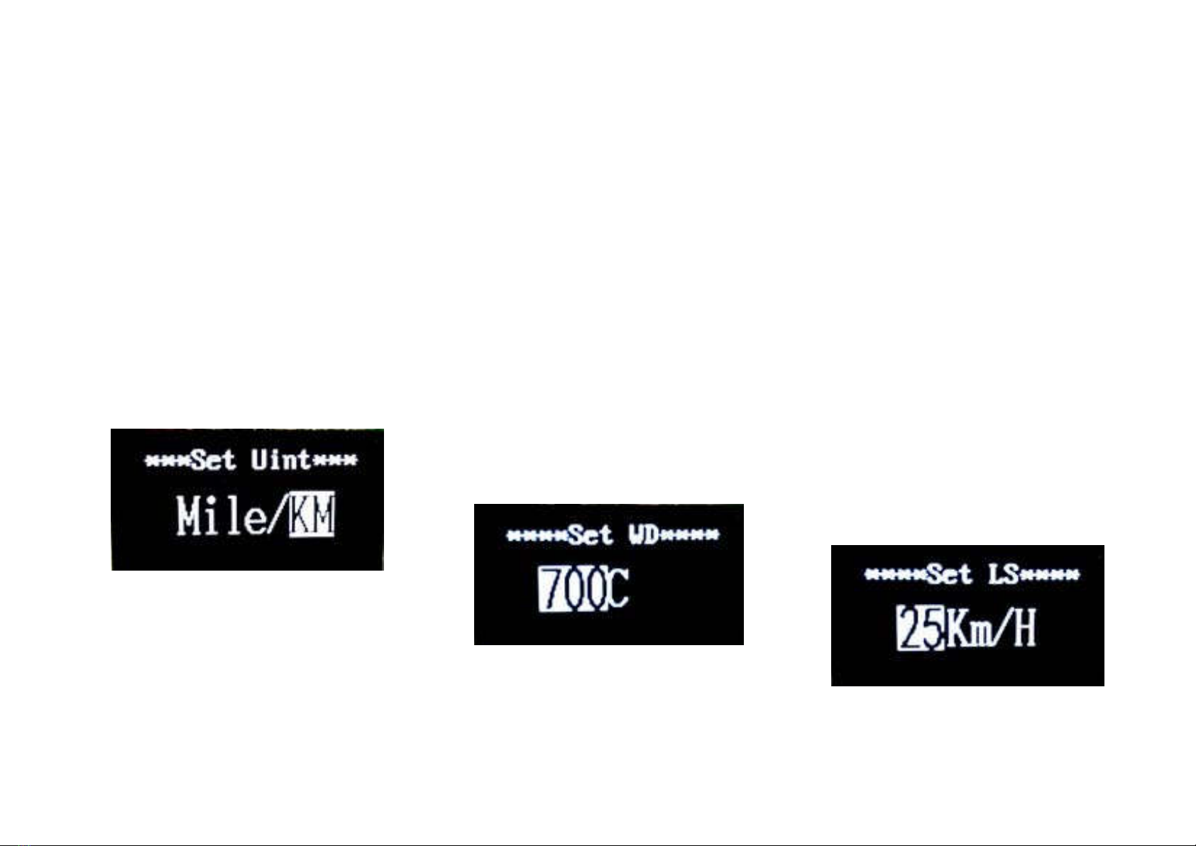
◆ Unit Mi/KMConversion
Set Unit represents unit settings.
To convert unit, press UP/DOWN to
increase or decrease until the desired
setting is displayed.
To store a changed setting, press MODE
button to access trip distance clearance
settings and the display will show OK then
returns to general selection settings
interface. The default unit is Metric.
Mile and Kilometer Conversion Settings
Interface
◆ Wheel DiameterSettings
Set WD represents wheel diameter
settings. Electable values are 16, 18, 20,
22,24, 26, 700C and 28. Default diameter of
Pluto R is 700C.
To change basic settings, press
UP/DOWN to increase or decrease until the
desired value is displayed.
To store a changed setting, press MODE
button and the display will show OK then
returns to general selection
settingsinterface.
Wheel Diameter Settings Interface
◆ Speed-limitSettings
Set LS represents limit speed settings.
When the running speed is faster than
limit speed, the eBike system will switch off
automatically. Limit speed range is 12Km/h
to 40Km/h.Limit speed default value of Pluto
R is 32Km/h.
To change basic settings, press
UP/DOWN to increase or decrease until the
desired value is displayed.
To store a changed setting, hold MODE
for 2 s and the display will display OK
then returns to general selection
settingsinterface.
Limit Speed Settings Interface

11
◆ Battery Power barSettings
VOLrepresents voltage settings.Each
barrery presents a voltage value.5 bars
voltage values must be entered one by one.
For example, VOL 1 is the first bar voltage
value, the default value is31.5V.
To set battery power bar, press
UP/DOWN to increase or decrease the
number.
To store a changed setting and access
the second bar, press MODE button.
By analogy, after 5 bars voltage values
is entered, hold MODE to confirm and return
to the previous menu.
Battery Power Bar Settings
Personalized Parameter Settings
Personalized Parameter Settings can
match various requirements in use. There
are 8 settings items, such as Power
assistant level Settings, Slowly Start up
Settings, Power- on Password Settings and
Exit settings.
Hold UP and DOWN button more than 2
seconds to enter general settings, then use
the same manner to enter personalized
parameter settings selection interface.
Press UP or DOWN button to choose the
personalized parameter settings items, then
press MODE button to enter the
corresponding settings interface.
Personalized parameter settings Interface
◆ Power Assistant Level Settings
Power Assistant Leveloption
In assistance level settings, there are 8
modes to select: 0-3, 1-3, 0-5, 1-5, 0-7,
1-7,0-9 , 1-9. The default mode is0-5.
To select the mode of assistance level,
press UP/DOWN to increase or decrease
until the desired setting is displayed.
To store the changed setting and access
the PAS ratio settings page, press MODE
button.
PAS Mode option Interface

12
PAS Ratio settings
To modify the value of PAS ratio can
match the different requirements.
For example, the range is “45-55
percent” of 1 level, bottom value can be
modified and the default is 50 percent.
Press UP or DOWN button to increase
or decrease the number. Press MODE
button to confirm and turn to the next PAS
ratio settings. 9 levels is the maximum. After
all PAS ratio inputted, press MODE button
to confirm and return to general selection
settings interface. Various symbol
definitions please refer to Attached list 2.
PAS Ratio Interface
◆ Slowly Start upSettings
Slow Start represents slowly start up.
The range is 1-4, 4 is the slowest.
To change slowly start-up settings,press
UP or DOWN button to select,press MODE
button to confirm and the meter will display
OK then return to general selection settings
interface. The default value is1.
Interface of slowly settings up
◆ Power-on Password Settings
P2:0000 represents power-on password
settings. The default power-on password is
1212.
To access the power-on password
settings, press UP/DOWN to modify the
value and then press MODE to confirm digit
one by one until the correct 4-digit password
is completed, and then press MODE to
access power-on password enable settings
interface, otherwise stay on the password
inputstate.
Power-on Password Entering Interface

13
Power-on Password Enable/Disable
Press MODE button to enter power-on
password modify interface. Press UP or
DOWN button to select Disable or Enable
and press MODE button to confirm.
Power-on Password default is Enable. If
you choose Enable, press MODE button to
enter Power-on Password Modify interface,
otherwise exit the power-on password
settings interface.Default power-on
password value is1212.
Power-on Password Disable/Enable
Interface
Power-on Password Modify
When the display shows “Password Set,
P3”, press UP/DOWN to modify the value
and then press MODE to confirm digit one
by one until the new 4-digit password is
completed.
To store the new power-on password,
hold MODE button for 2 s and then exit
settings.
When switching the eBike system on
next time, the display will show P1,0000,
please input the new password to power on.
Power-on Password Modify Interface
◆ Exitsettings
In the settings state, press MODE button
to confirm the input. Hold MODE button
more than 2 seconds to save the settings
and then exit the current settings. Hold
DOWN button more than 2 seconds to
cancel the operating but not saving the
settings data, and then return to
previousmenu.
■ If there is not any operations in one
minute, display will exit the settings state
automatically.

14
Recover default settings
dEF means recover default settings.
Press both UP and MODE button more than
2 seconds to enter recover default settings.
Press UP or DOWN button to choose Y or N.
Y means that recovers default settings. N
means that do not recover default settings.
When
it is Y, hold MODE button more than 2
seconds to recover default settings, the
display showsd EF-00 at the same time,and
then return to general display state.The
default state is No.
Recover Default Settings Interface
Quality assurance and warranty
scope
1. Warranty
1). The warranty will be valid only for
products used in normal usage
andconditions.
2).The warranty is valid for 24 months
after the shipment or delivery to the
customer.
2.Others
The following items do not belong to our
warranty scope.
1) Shell is broken when display is out
of thefactory.
2) Wire isbroken.
3) It cannot bedemolished.
4) The damage is caused by wrong
installation oroperation.
5) Beyond the warrantytime.
6) The fault or damage is caused by the
force majure (such as fire, earthquake, etc,)
or natural disasters like lighting,etc.
Connection layout
Connector line sequence
Display-sideConnector
Display-sideadapter
Switch wiring

15
Line sequence table
■
Somewireusethewater-proofconnector,usersarenotabletoseethe
inside color.
Operation Cautions
Be care of the safety use. Don’t attempt to release the connector
when battery is on power.
◆ Try to avoidhitting.
◆ Do not modify system parameters to avoid
parametersdisorder.
◆ Make the display repaired when error codeappears.
Attached list 1: Error code definition
Error Code Definition
21 Current Abnormality
22 Throttle Abnormality
23 Motor Abnormality
24 Motor Hall Abnormality
25 Brake Abnormality
30 Communication Abnormality
Attached list 2:Power assist table
Level
Level
Item
1 2 3 4 5 6 7 8 9
0-3/1-3 50%
74%
92%
— — — — — —
0-5/ 1-5
50%
61%
73%
85%
96%
— — — —
0-7/ 1-7
40%
50%
60%
70%
80%
90%
96%
— —
0-9/ 1-9
25%
34%
43%
52%
61%
70%
79%
88%
96%
Line sequence Color Function
1 Red(VCC) +
2 Blue(K) Lock
3 Black(GND) -
4 Green(RX) RX
5 Yellow(TX) TX

16
Seat position
In order to allow comfortable, fatigue-free
and safe driving, the saddle and handlebar
height must be adapted to the body size.
The saddle height is correct when sitting
with the leg not fully extended (1), the foot
rests on the pedal in the lowest position.
The tiptoes must still touch the ground.
The handlebar height is correct when the
handlebar stem (2) with the upper edge of
the saddle (3) is level or slightly higher.

17
Adjust saddle height
WARNING
A not completely closed quick-release lever
can open again. This can cause the saddle
to move down while driving. This can lead to
serious falls.
the flip of the quick release lever must go so
hard that it requires the palm of your hand.
Only then the tension is strong enough.
make sure that the saddle cannot be pulled
out more than the mark (3).
- Release the quick-release lever (1),
determine the seat height and tighten the
lock.
- By adjusting the nut (2) on the quick
release lever, the clamping force can be
regulated.
The quick release lever (1) must be with
close noticeable backpressure.
Adjust saddle
The saddle can also be tilted and
adjusted in the longitudinal direction.
- Loosen the screw (1).
- Place the saddle in the desired
horizontal position or move it forwards
or backwards and tighten the screw (1).
NOTE
To avoid seat discomfort, the saddle
should be adjusted as level as possible.

18
Adjust handlebar
Adjust the handlebar position
- Loosen the clamping screws (1) with
hexagon socket wrench.
- Determine handlebar position and tighten
handlebar clamping screws.
NOTE
Ensure tension-free laying of the cables and
avoid extreme turning of the handlebars
upwards or downwards.

19
Important safety instructions for the charger
Before putting the charger into operation,
please read these safety instructions.
WARNING
Protect charger from child hands. To
prevent injury risks, you may only charge
lithium-ion batteries. Other types of
batteries can explode when charged. this
can lead to personal injury and material
damage.
the use of accessories or rechargeable
batteries not sold or recommended by us
may result in fire, electric shock or personal
injury.
Be sure to avoid operating the unit in humid
or wet conditions.
Be sure to avoid water entering the unit. If
liquid has entered: Disconnect the charger
from the mains immediately and take it to
your dealer for checking.
Make sure the surface is level and secure
on the device.
Disconnect the device from the mains when
not in use.
Do not pull on the cable to avoid damage to
the cable and thus the risk of electric shock.
Make sure the power cord is rolled up or
folded after use.
Do not operate the charger with a damaged
cable or plug. Ensure immediate
replacement by a specialist.
Do not operate the charger after it has been
struck, dropped or otherwise damaged.
Do not disassemble the charger yourself.
Incorrect installation may result in electric
shock or fire. To prevent electric shock,
disconnect the charger from the mains
before cleaning it.
The appliance should only be cleaned with
a dry cloth or a rag. Never use oil, water or
solvents.
An extension cord should only be used if
absolutely necessary. the use of extension
cords that are out of order may result in fire
or electric shock. If an extension cable
needs to be used then make sure that
- The number of pins of the connector in
number, size and shape of the charger
exactly matches.
- the extension cable is correctly wired and
in good electrical condition.
- The cable cross-section is large enough
for the AC rating of the charger.
- the extension cord has no visible damage.
- When using cable drums, the drum is fully
unwound.

20
Charger functions
This charger is suitable for Li-ion batteries.
The LED (LED 1) on the charger keeps you
constantly informed of the operating status.
You will be informed about the status and
charging of the battery at a glance.
Disorders
Please check:
- Is the power cable connected correctly?
- Are the contacts of the charger and the
battery clean and not damaged or bent?
- Is the battery damaged or defective?
If proper battery charging is not possible:
- Check whether the socket carries voltage,
if necessary connect it to other consumers.
- Check for perfect contact with the
connectors.
- If charging is still not possible, please have
the battery and charger checked by the
dealer.
charging cycle and LED indicators for lithium-ion battery
LED Model
Green Battery not yet connected
Red Charging process / electricity is flowing
Green Charging finished / no current is flowing
This manual suits for next models
1
Table of contents
Languages:
Other RBSM Bicycle manuals