Schweißkraft EG 5 User manual

EG 5
Instruction Manual
EG 5
EG 5
Electrode grinding machine

2 EG 5 | Version 1.08 | EN
Imprint
Product identification
Electric grinder Item number
EG 5 1692005
Manufacturer
tuermer Maschinen GmbH
Dr.-Robert-Pfleger- tr. 26
D-96103 Hallstadt
Fax: 0049 (0) 951 96555 - 55
E-Mail: info@schweißkraft.de
Internet: www.schweißkraft.de
Indications regarding the operating instructions
Original instruction
according DIN EN I O 20607:2019
Edition: 28.09.2021
Version: 1.08
Language: English
Author: M
Indications regarding the copyright
Copyright © 2021 türmer Maschinen GmbH, Hallstadt,
Germany.
ubject to technical modifications and error.
Contents
1 Introduction ............................................ 3
1.1 Copyright ........................................................... 3
1.2 Customer service...............................................3
1.3 Limitation of liability............................................3
2 Safety ...................................................... 3
2.1 ymbol explanation ...........................................3
2.2 Responsibility of the operator ............................ 4
2.3 Qualification of the staff ..................................... 5
2.4 Personal protective equipment .......................... 5
2.5 General safety regulations................................. 6
2.6 afety data sheets............................................. 6
2.7 afety devices ................................................... 6
3 Intended Use........................................... 6
3.1 Reasonably foreseeable misuse........................7
3.2 Residual risks .................................................... 7
4 echnical Data........................................ 7
4.1 Type plate..........................................................7
5 ransport, Packaging, Storage ............. 8
5.1 Delivery and Transport ......................................8
5.2 Packaging..........................................................8
5.3 torage ..............................................................8
6 Description of the Device ...................... 8
6.1 Overall view .......................................................8
6.2 Accessories ....................................................... 9
7 Electrical Connection.............................10
8 Installation and Commissioning............10
9 Service.....................................................10
9.1 Operation........................................................... 10
10 Care, Maintenance and Repair.............11
10.1 Maintenance ...................................................11
10.2 Care by cleaning............................................. 12
10.3 Grinding wheel change................................... 12
10.4 Troubleshooting.............................................. 12
11 Disposal, Recycling of used Devices..13
11.1 Decommissioning ...........................................13
11.2 Disposal of electrical equipment..................... 13
11.3 Disposal via municipal collection
points..............................................................13
12 Spare parts.............................................13
12.1 Ordering spare parts....................................... 13
12.2 pare parts drawing........................................14
13 Electrical Wiring Diagram.....................15
14 EC Declaration of Conformity..............16
15 Notes......................................................17

Introduction
EG 5 | Version 1.08 | EN 3
1 Introduction
You have made a good choice by purchasing the
electrode grinder from chweißkraft.
Read the operating instructions carefully before
using the machine.
These are an important part and must be kept near the
machine and accessible to every user.
The operating instructions inform you about the proper
commissioning, the intended use as well as the safe and
efficient operation and maintenance of the electrode
grinding machine.
In addition, observe the local accident prevention regula-
tions and general safety regulations for the area of appli-
cation of the electrode grinding unit.
1.1 Copyright
The contents of these instructions are protected by copy-
right and are the sole property of türmer Maschinen
GmbH. Their use is permitted within the scope of the use
of the electrode grinding unit. Any other use is not per-
mitted without the written consent of the manufacturer.
Passing on and reproduction of this document, utilisation
and communication of its contents are prohibited unless
expressly permitted. Violations will result in liability for
damages. We register trademark, patent and design
rights to protect our products, insofar as this is possible
in individual cases. We emphatically oppose any infrin-
gement of our intellectual property.
1.2 Customer service
Please contact your dealer if you have questions con-
cerning your device or if you need technical advice. They
will help you with specialist information and expert ad-
vice.
Germany:
türmer Maschinen GmbH
Dr.-Robert-Pfleger- tr. 26
D-96103 Hallstadt
Repair service:
Fax: 0049 (0) 951 96555-111
E-Mail: [email protected]
Spare part orders:
Fax: 0049 (0) 951 96555-119
E-Mail: [email protected]
We are always interested in valuable experience and
knowledge gained from using the application which then
could be shared and be valuable to develop our products
even further.
1.3 Limitation of liability
All information and notes in these operating instructions
were summarised while taking applicable standards and
rules, the state-of-the-art technology and our long-term
knowledge and experiences into consideration.
In the following cases the manufacturer is not liable for
damages:
- Non-observance of the operating instructions,
- Inappropriate use
- Use of inexperienced staff,
- Unauthorised modifications
- Technical changes,
- Use of not allowed spare parts.
The actual scope of delivery may deviate from the ex-
planations and presentations described here in case of
special models, when using additional ordering options
or due to latest technical modifications.
The obligations agreed in the delivery contract, the gen-
eral terms and conditions as well as the delivery condi-ti-
ons of the manufacturer and the legal regulations at the
time of the conclusion of the contract are applicablen.
2 Safety
This section provides an overview of all important safety
packages for the protection of the operating personnel
as well as for safe and fault-free operation. Other task
based safety notes are included in the paragraphs of the
individual phases of life.
2.1 Symbol explanation
Safety instructions
The safety notes in these operating instructions are high-
lighted by symbols. The safety notes are introduced by
signal words which express the concern of the risk.

4 EG 5 | Version 1.08 | EN
Safety
ips and recommendation
It is necessary to observe the safety notes written in
these operating instructions in order to reduce the risk of
personal injuries and damages to property.
2.2 Responsibility of the operator
The operator is the person who operates the machine
himself for commercial purposes or who makes it availa-
ble to a third party for use or application and who bears
the legal product responsibility for the protection of the
user, personnel or third parties during operation.
Obligations of the Operator:
If the machine is used in the commercial sector, the ope-
rator of the machine is subject to the legal obligations for
occupational safety. Therefore, the safety instructions in
these operating instructions as well as the safety, acci-
dent prevention and environmental protection regulati-
ons valid for the area of application of the machine must
be observed. The following applies in particular:
- The operator must inform himself about the appli-
cable occupational health and safety regulations
and determine additional hazards in a hazard as-
sessment that result from the special working con-
ditions at the place of use of the machine. He must
implement these in the form of operating instructi-
ons for the operation of the machine.
- During the entire period of use of the machine, the
operator must check whether the operating instruc-
tions he has drawn up correspond to the current
status of the regulations and, if necessary, adapt
them.
- The operator must clearly regulate and define the
responsibilities for installation, operation, trouble-
shooting, maintenance and cleaning.
- The operator must ensure that all persons handling
the machine have read and understood these in-
structions. In addition, he must train the personnel
at regular intervals and inform them about the dan-
gers.
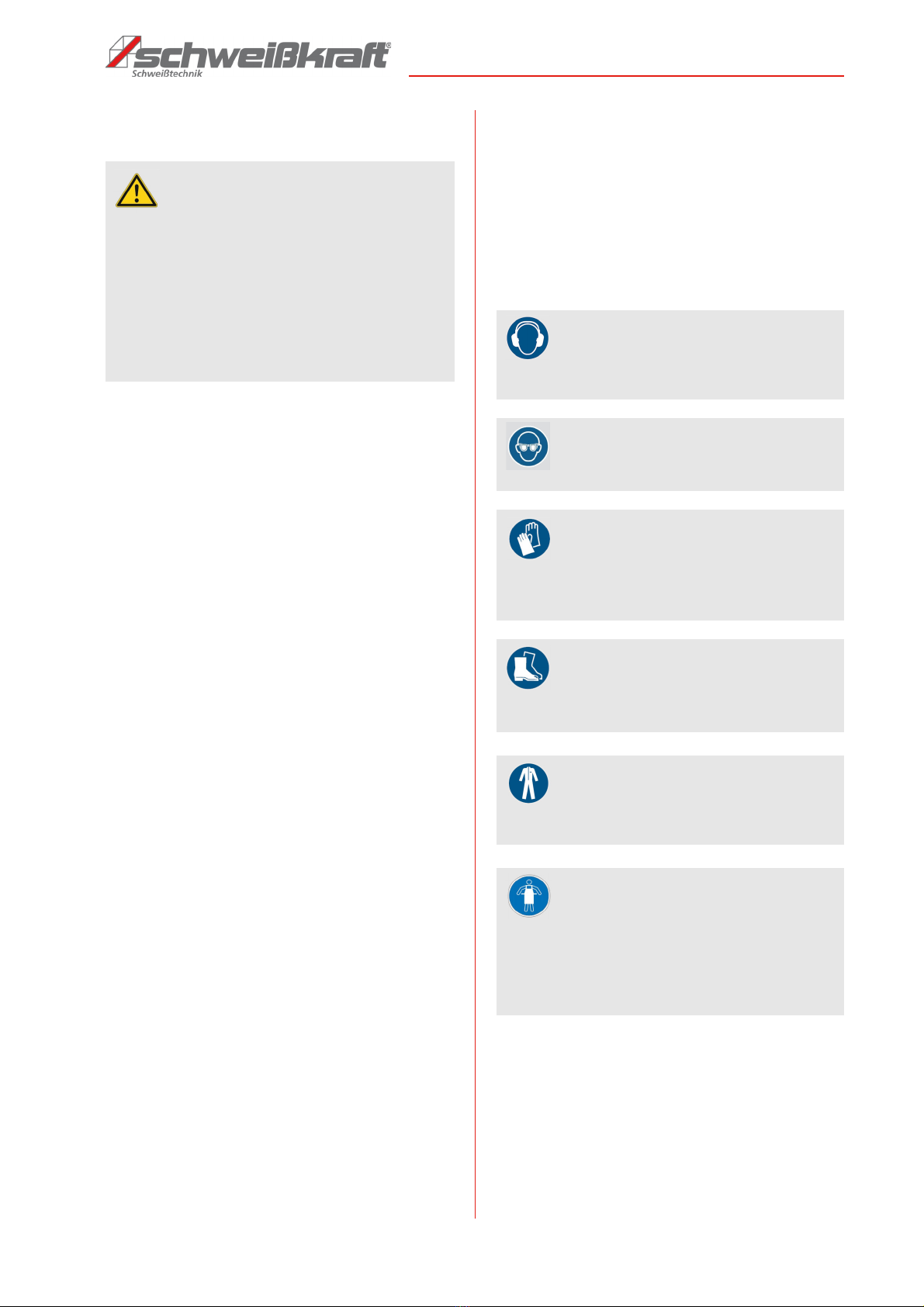
- The operator must provide the personnel with the
required protective equipment and instruct them to
wear the required protective equipment.
Furthermore, the operator is responsible for ensuring
that the machine is always in technically perfect condi-
tion. Therefore, the following applies:
- The operator must ensure that the maintenance in-
tervals described in this manual are observed.
- The operator must have all safety devices checked
regularly for functionality and completeness.
DANGER!
This combination of symbol and signal word indicates
an imminently hazardous situation which, if not avoi-
ded, will result in death or serious injury.
WARNING!
This combination of symbol and signal word indicates
a potentially dangerous situation that will result in
death or serious injury if not avoided.
CAU ION!
This combination of symbol and signal word indicates
a potentially hazardous situation which, if not avoi-
ded, may result in minor or slight injury.
A EN ION!
This combination of symbol and signal word indicates
a potentially hazardous situation which, if not avoi-
ded, may result in damage to property and the env-
ironment.
NO E!
This combination of symbol and signal words indica-
tes a possibly dangerous situation which may lead to
property and environmental damages if they are not
avoided.
ips and recommendation
This symbol highlights useful tips and recommenda-
tion as well as information for all efficient and trou-
ble-free operation.

Safety
EG 5 | Version 1.08 | EN 5
2.3 Qualification of the staff
Only persons who can be expected to perform this work
reliably are permitted for all work. Persons whose ability
to react is influenced by drugs, alcohol or medication, for
example, are not permitted.
In these operating instructions, the qualifications of the
persons listed below are named for the various tasks:
Operator:
The operator has been instructed by the operator about
the tasks assigned to him and possible dangers in case
of improper behaviour. The operator may only perform
tasks that go beyond operation during normal operation
if this is specified in these operating instructions and the
operator has expressly entrusted him with them.
Qualified electrician:
Due to their technical training, knowledge and
experience as well as knowledge of the relevant
standards and regulations, the qualified electrician is
able to carry out work on electrical systems and to
recognize and avoid possible dangers independently.
Specialist staff:
Due to their technical training, knowledge and
experience as well as knowledge of the relevant
standards and regulations, the specialist staff is able to
carry out the work assigned to them and to
independently recognize and avoid possible dangers.
Manufacturer:
Certain work may only be carried out by qualified
personnel from manufacturer. Other staff is
not authorized to carry out this work. Contact our
customer service to carry out the work
2.4 Personal protective equipment
The personal protective equipment serves to protect per-
sons against impairments of safety and health while wor-
king. The staff member has to wear personal protec-tive
equipment while performing different tasks on and with
the machine which are indicated in the individual para-
graphs of these instructions.
The personal protective equipment is explained in the
following paragraph:
WARNING!
Danger in case of insufficient quali-
fication of persons!
Insufficiently qualified persons cannot assess the
risks when handling the machine and expose them-
selves and others to the risk of serious or fatal inju-
ries.
- All work must only be carried out by qualified per-
sons.
- Keep insufficiently qualified persons away from the
work area.
Hearing protection
Hearing protection protects the ears from hearing
damage caused by noise.
Safety goggles
Protective goggles protect the eyes from flying parts.
Use suitable protective gloves
The protective gloves protect the hands from sharp-
edged components, as well as from friction, abra-
sions or deeper injuries.
Safety boots
The safety boots protect the feet from crushing, fal-
ling parts and slipping on slippery surfaces.
Protective clothing
The protective clothing is tight-fitting clothing with low
tear resistance.
Protective apron
The chemical protection apron protects against cont-
amination and chemicals.
The heat protection apron protects against heat.
The stab protection apron protects against mechani-
cal injuries.

6 EG 5 | Version 1.08 | EN
Intended Use
2.5 General safety regulations
- Before commissioning, check the device for exter-
nally visible damage and defects.
- After grinding, do not remove the electrode holder
until the motor has come to a standstill.
- Repair defects and damage immediately.
- Work on the electrical equipment may only be car-
ried out by a qualified electrician.
- Do not use the device in damp wet conditions, rain, etc.
- Make sure that the switch is switched off when
plugging the plug into the socket to prevent in-
advertent startup.
- The operator must follow the instructions for opera-
ting the device.
- Memorize the switch positions of the device to re-
act properly in an emergency.
- Please interrupt the power supply immediately if
smoke, odor or noise occur during operation.
- Check that the sanding device is firmly installed.
- Check the tightness of the unit before switching on
the power supply.
- Then check the attachment of the grinder one more
time.
- Use the cover plate while working.
- It is forbidden to bring your hand into the grinding
zone during work.
- Make sure the power supply is turned off and dis-
connected when cleaning the consumables.
- Be sure to use the tungsten pin clamp that meets
the specifications of the tungsten electrode.
- Non-professional personnel may not remove the
device housing.
2.6 Safety data sheets
afety data sheets for hazardous materials can be obtai-
ned from your specialist dealer or by phone: +49 (0)951/
96555-0. pecialist dealers can find safety data sheets
in the download area of the partner portal.
2.7 Safety devices
3 Intended Use
The EG 5 tungsten electrode grinder is only to be used to
grind commercially available TIG welding electrodes. It is
mainly used for sharpening tungsten rods, tungsten
electrodes, tungsten needles and welding pins. The de-
vice is only to be used for electrode diameters of 1.6 mm
to 5.0 mm and a minimum electrode length of 35 mm.
The device is not suitable for use with tungsten electro-
des containing thorium oxide.
Intended use also includes compliance with all informa-
tion in these instructions.
WARNING!
Danger from life from non-functio-
ning safety devices!
If safety devices do not work or are disabled, there is
a risk of serious injuries or even death.
- Before starting work, check whether all safety de-
vices are functional and correctly installed.
- Never bypass or disable the safety devices.
- Make sure that all safety devices are always acces-
sible.
WARNING!
Danger from uncontrolled restart!
Uncontrolled switching on of the device can lead to
serious injuries.
- Before switching on again, ensure that the cause of
the switch-off has been eliminated and that all
safety devices are installed and functional.
- Do not switch on the electric grinder until there is no
longer any danger.

echnical Data
EG 5 | Version 1.08 | EN 7
3.1 Reasonably foreseeable misuse
Any use that goes beyond the intended use or is different
is deemed to be misuse.
Possible misuse can be:
- Failure to observe the signs of wear and damage.
- Use of the device in potentially explosive and fire-
prone environments without appropriate fire pro-
tection measures and in rooms with insufficient
fresh air supply.
- ervice work by untrained or unauthorized person-
nel.
- Operating the device if the operating instructions
have not been read and understood in full.
- Installation of spare parts and use of accessories
or equipment that are not approved by the manu-
facturer.
- Improper use of the electrode grinder.
- Modifications to the device, accessories or protec-
tive devices without the consent of the manufactu-
rer.
- Use of the device with parameters that do not
match the information on the nameplate.
- Deliberate or careless handling of the device du-
ring operation.
Misuse of the device can lead to dangerous situations.
In the event of constructive and technical changes to the
electrode grinder takes over the company türmer Ma-
schinen GmbH no liability.
Claims of any kind due to damage due to improper use
are excluded.
3.2 Residual risks
Even if all safety regulations are observed and the ma-
chine is used correctly, there are still residual risks,
which are listed below.
- There is a risk of injury to the upper limbs (e.g.
hands, fingers).
- Heat development on components can lead to
burns and other injuries.
- Electrical hazard from contact with parts and high
voltage (direct contact) or with parts that are under
high voltage due to a defect in the device (indirect
contact).
4 echnical Data
4.1 ype plate
Fig. 1: Type plate EG 5
ype EG 5
Length (product) approx. 225 mm
Width/depth (product)
approx.
150 mm
Height (product) approx. 195 mm
Net weight approx. 4,1 kg
upply voltage 220- 230 V
Current type AC
Mains frequency 50-60 Hz
Electrode diameter 1,6 - 5,0 mm
Max. electrode length 35 mm
Grinding angle 15-60°
peed 6500 min¯¹
Diamond disk diameter 90 mm
Drive motor output 0,07 kW

8 EG 5 | Version 1.08 | EN
ransport, Packaging, Storage
5 ransport, Packaging, Storage
5.1 Delivery and ransport
Delivery
Check the device for visible transport damage after deli-
very. If the device shows damage, it must be reported
immediately to the transport company or the dealer.
Scope of delivery:
- Electric grinder EG 5
- Diamond disc Ø 90 mm
- One collet chuck each 1.6 / 2.0 / 2.4 / 3.2 / 4.0 mm
- Instruction Manual
5.2 Packaging
All used packaging materials and packaging aids are
recyclable and should be taken to a materials recycling
depot to be disposed of.
The delivery packaging is made of cardboard, so please
dispose carefully by having it chopped up and given to
the recycling collection.
The film is made of polyethylene (PE) and the cushioned
parts of polystyrene (P ). These materials should be ta-
ken to a collection point for recyclable materials or to the
local waste disposal company.
5.3 Storage
The device must be thoroughly cleaned before storing it
in a dry, clean and frost-free environment.
6 Description of the Device
6.1 Overall view
Fig. 2: Description of the device EG 5
1 Protective sleeve
2 djusting screw
3 Cover plate
4 Grinding wheel
5 Movable cover plate
6 Rotating angle scale
7 DC motor
8 ecuring bushing
9 Rectifier bridge
10 Rotary knob
11 witch
12 Fuse
13 Power connector
16

Description of the Device
EG 5 | Version 1.08 | EN 9
Fig. 3: Description of the device EG 5
6.2 Accessories
- Diamond disc
Item number: 1692050
- Electrode holder
Item number: 1692051
- Collet chuck 1,6 mm
Item number: 1692052
- Collet chuck 2,0 mm
Item number: 1692053
- Collet chuck 2,4 mm
Item number: 1692054
- Collet chuck 3,2 mm
Item number: 1692055
- Collet chuck 4,0 mm
Item number: 1692056
- Collet chuck 5,0 mm
Item number: 1692057
- Protective glass
Item number: 1692058
- Main switch
Item number: 1692059
- Rubber foot set
Item number: 1692060
- eal
Item number: 1692061
- Fixing screw for diamond disc
Item number: 1692062
- pacer washer
Item number: 1692063
- Adjusting nut
Item number: 1692064
- Diamond disc
Item number: 1692065
- Indicator
Item number: 1692066
- Cleaning brush
Item number: 1692005
1 Protective sleeve
2 Adjusting screw
3 Dust cover / protective glass
4 Grinding
5 Movable cover plate
6 Rotating angle scale
7 DC motor
8 ecuring bushing
9 Rectifier bridge
10 Rotary knob
11 witch
12 Fuse
13 Power connector
14 Electrode terminal / Clamping
sleeve
2 Round handle for
adjusting
1 Protective
sleeve
15 Locking
knob
Electrode clamping device / Electrode holder

10 EG 5 | Version 1.08 | EN
Electrical Connection
7 Electrical Connection
It must be ensured that the power connection has the
same characteristics (voltage, mains frequency) as the
motor.
8 Installation and Commissioning
9 Service
Always follow the safety instructions and follow the rele-
vant regulations.
Before switching on the device, the electrode holder
must always be in the supply channel.
9.1 Operation
Prior to commissioning, make sure that the mains
voltage and mains frequency stated on the rating plate
match the data of your mains supply. The connection is
only permitted on sockets with protective contact.
The device is equipped with a clamping sleeve for cer-
tain electrode diameters. It is possible that another collet
must be used for a different diameter. The device must
then be converted accordingly.
tep 1: Turn the rotating body (A) to the required angular
position by referring to the angle indicator (C).
et the grinding angle according to the required
grinding effect and tighten the fastening knob (B,
Fig.4) on both sides.
Fig. 4: Angular adjustment of the rotary body
tep 2: et the extension length of the tungsten
electrode (Item 2, Fig. 2, the lock knob is on the
rotary body and the tungsten electrode tip is bet-
ween the two lines of the longitudinal position
setting block).
tep 3: Turn the upper (Item 2, Fig. 2) and lower adjust-
ment knob to the highest position.
DANGER!
Danger of electrocution!
Work on the electrical connection may only be carried
out by qualified electricians.
CAU ION!
When grinding, the protective glass must always be
closed.
Ear protection
When using the tungsten electrode grinder, wear ear
protection!
The A - weighted - equivalent continuous sound
pressure level at the workplace is higher than 70 dB
(A). Measured according to EN I O 11201.
Eye protection
The goggles protect the eyes from flying parts and
liquid splashes.
Use suitable Protective gloves
The protective gloves protect the hands from sharp-
edged components as well as from friction, abrasions
or deeper injuries.
Safety shoes
The safety shoes protect the feet against bruising,
falling parts and slipping on slippery surfaces.
NO E!
Before use, check the validity of the inspection period
with reference to the relevant statutory safety regula-
tions for electrical installations and equipment.
Wear respiratory protection!
The dust mask protects against coarse dust particles.
B
C
A

Care, Maintenance and Repair
EG 5 | Version 1.08 | EN 11
Grinding the tungsten electrode
tep 4: Insert the electrode into the grinder to start the
grinding process. Use the left hand to actuate
the adjustment handle (item 2, Fig. 2) for the
upward and downward movement of the grinding
tip length infeed. Use the right hand to turn the
adjustment handle (Item 16. Fig.2) to adjust the
position of the tip.
tep 5: Observe the degree of grinding. When the requi-
red effect has been achieved, the tungsten
electrode can be removed.
After completion of the work order
tep 6: Turn off the power after grinding, remove the
tungsten electrode clamp (Fig.3). Turn the loc-
king knob (Item 15, Fig. 3) open. Remove the
Tungsten electrode clamp (Pos.14, Fig.3) and
the electrode. Place the finished tungsten
electrode in a protected location.
tep 7: Turn the movable cover plate (Pos.5, Fig.2) in
the bottom of the unit so that you can remove the
coarse dust.
If this notice is disregarded, sanding dust may leak from
the supply channel or become lodged in the supply chan-
nel.
At the next feeding, the electrode holder may jam in the
feed channel due to the grinding dust deposit.
Before repair, - change the maintenance and grinding
wheel and after use pull out the mains plug.
10 Care, Maintenance and Repair
r
- After using the equipment, the wearing parts must
be cleaned promptly. Keep the device clean.
- Add lubricants to the rotating parts in a timely man-
ner to ensure smooth rotation.
- It is forbidden to service the device in the area of
corrosive gases or smoke.
- Use a stable voltage source for the power supply.
- Make sure the power cord is undamaged to pre-
vent fire or electric shock.
- Disconnect the power supply during maintenance.
10.1 Maintenance
If the device does not work properly, contact a dealer or
our customer service. The contact details can be found
in chapter 1.2 Customer ervice.
NO E!
Before switching on the device, the electrode holder
must always be in the supply channel.
Before the electrode holder is removed, the motor
must come to a standstill.
CAU ION, MAIN ENANCE!
Always unplug the power cord before servicing.
Maintenance work extends the life of the machine if it
is carried out regularly and professionally.
Before repair, maintenance and grinding wheel
change and after use pull the mains plug.
NO E!
After servicing, maintenance and repair work, check
that all panels and protective devices are correctly
installed on the Electric grinder again.
Damaged safety devices and equipment must be
repaired or replaced by the customer service.
DANGER!
Repairs or maintenance may only be carried out by
qualified and trained specialist personnel.
- Use only original spare parts.
NO E!
Before servicing and maintaining the Electric Grinder,
the maintenance instructions must be read carefully.
The use of the Electric Grinder is only permitted for
persons who are familiar with the Electric Grinder.
DANGER!
Danger due to insufficient qualifica-
tion of persons!
Insufficiently qualified persons can not assess the
risks involved in maintenance work on the Electric
Grinder and expose themselves and others to the
risk of serious injury.
- All maintenance work should only be carried out by
qualified persons.
ips and recommendations
To ensure that the device is always in good opera-
ting condition, regular care and maintenance work
must be carried out.

12 EG 5 | Version 1.08 | EN
Care, Maintenance and Repair
10.2 Care by cleaning
- Clean the device externally with a cloth.
- Do not use a damp cloth or light oil, solvents or al-
cohol to clean the unit. Otherwise, it may cause fa-
ding or deformation.
- Under the condition that the unit is heavily soiled,
you can use a piece of cloth and put in a neutral
detergent dilution, then dry until slightly damp. Use
the slightly damp cloth to wipe off the product. Af-
ter the dirt has been removed, dry the product with
a soft, dry cloth.
10.3 Grinding wheel change
tep 1: Turn the rotating body backwards.
tep 2: Remove the front panel (protective glass) 3 from
the unit by pulling it upwards.
tep 3: Unscrew the fixing screw 1 of the sanding plate
4.
tep 4: Remove the sanding plate 4.
Fig. 5: Replacing the grinding wheel
tep 5: When inserting the new sanding plate, make
sure that the spacer 2 is inserted.
tep 6: Reassemble the remaining components in re-
verse order.
10.4 roubleshooting
In case of malfunction or wear of a part, contact your
local dealer.
A EN ION!
Perform a device cleaning before!
12
3
1

Disposal, Recycling of used Devices
EG 5 | Version 1.08 | EN 13
11 Disposal, Recycling of used
Devices
Please take care in your own interest and in the interest of
the environment that all component parts of the ma-chine
are only disposed of in the intended and permitted way.
11.1 Decommissioning
Disused equipment must be taken out of service immedi-
ately in order to avoid later misuse and endangering the
environment or people.
- Dispose of all environmentally hazardous fluids from
the old device.
- If necessary, disassemble the machine into manage-
able and usable assemblies and components.
- upply the machine components and operating materi-
als to the appropriate disposal channels.
11.2 Disposal of electrical equipment
Electrical equipment contains a variety of recyclable ma-
terials and environmentally harmful components.
These components must be separated and properly dis-
posed of. If in doubt, contact municipal waste manage-
ment.
If necessary, the help of a specialized waste disposal
company can be used for the treatment.
11.3 Disposal via municipal collection
points
Disposal of used electrical and electronic equipment
(Applicable in the countries of the European Union and
other European countries with a separate collection sys-
tem for these appliances).
The symbol on the product or its packaging indi-
cates that this product should not be treated as normal
household waste, but must be returned to a collection
point for the recycling of electrical and electronic equip-
ment. By helping to properly dispose of this product, you
are protecting the environment and the health of others.
Environment and health are endangered by improper
disposal. Material recycling helps to reduce the con-
sumption of raw materials. For more information about
recycling this product, contact your local community, mu-
nicipal waste management, or the shop where you pur-
chased the product.
12 Spare parts
12.1 Ordering spare parts
The spare parts may be purchased with the authorised
dealer.
Indicate the following basic information for requests or
orders of spare parts:
- Type of device
- Item No.
- Position No.
- Year of construction
- Quantity
- Required mode of dispatch (mail, freight, sea, air, ex-
press)
- Address of dispatch
pare parts orders without the aforementioned data can-
not be taken into account. The supplier shall deter-mine
the shipping type if no relevant data was provided.
Data on the machine type, item number and year of ma-
nufacture is listed on the type plate attached to the de-
vice.
Example
The engine for the Electric grinder
EG 5
must be ordered.
The engine has the number 5 in the spare parts drawing 1.
By ordering spare parts, send a copy of the spare parts
drawing (1) with the marked part (engine) and marked
positon number (5) to the dealer or spare parts depart-
ment and provide the following information:
Type of device:
Electric grinder
EG 5
Item number:
1692005
Drawing number:
1
Position number:
5
DANGER!
Danger of injury by the use of
wrong spare parts!
Dangers may result for the user and damages as well
as malfunctions may be caused by using wrong or
damaged spare parts.
- Only use original spare parts of the manufacturer or
spare parts admitted by the manufacturer.
- Always contact the manufacturer in case of uncer-tain-
ties.
LOSS OF WARRAN Y!
The manufacturer's warranty will become null and
void if non-permissible spare parts are used.

14 EG 5 | Version 1.08 | EN
Spare parts
12.2
Spare parts drawing
The following spare parts drawing is intended to help identify the necessary spare parts. To order, please send a copy of
the list of spare parts with the marked components to your dealer.
Fig. 6: pare parts drawing EG 5

Electrical Wiring Diagram
EG 5 | Version 1.08 | EN 15
13 Electrical Wiring Diagram
Fig. 7: Electrical wiring diagram

16 EG 5 | Version 1.08 | EN
EC Declaration of Conformity
According to Machinery Directive 2006/42/EC, Annex II 1.A
Manufacturer / distributor:
türmer Maschinen GmbH
Dr.-Robert-Pfleger- traße 26
D-96103 Hallstadt
hereby declares that the following product
Product group:
chweißkraft® Welding technology
Designation of the machine:
EG 5
ype of machine:
Electric grinder
Item number:
1692005
Serial number*:
____________________
Year of manufacture*:
20____
* please fill in according to the information on the type plate
Due to its design and construction, as well as in the version we have placed on the market, it complies with the relevant
basic health and safety requirements of the above-mentioned and subsequent EC directives.
Applicable EU Directives:
2014/30/EU EMV-Directive
2012/19/EU WEEE-Directive
2011/65/EU RoH -Directive
EU 2015/863:2015-03-31 Amendment of Annex II to Directive 2011/65 / EU
he following harmonized standards were applied:
DIN EN 61000-6-1:2007-10 Electromagnetic compatibility (EMC) - Part 6-1: Generic standards - Immunity for
residential, commercial and light-industrial environments (IEC 61000-6-1:2005)
DIN EN 61000-6-3:2011-09 Electromagnetic compatibility (EMC) - Part 6-3: Generic standards - Emission standard
for residential, commercial and light-industrial environments
(IEC 61000-6-3:2006 + A1:2010)
DIN EN 61000-3-2:2010-03 Electromagnetic compatibility (EMC) - Part 3-2: Limits - Limits for harmonic current
emissions (equipment input current <= 16 A per phase) (IEC 61000-3-2:2005 +
A1:2008 + A2:2009)
DIN EN 61000-3-3:2014-03 Electromagnetic compatibility (EMC) - Part 3-3: Limits - Limitation of voltage changes,
voltage fluctuations and flicker in public low-voltage supply systems, for equipment
with rated current <= 16 A per phase and not subject to conditional connection
(IEC 61000-3-3:2013)
DIN EN 62841-1:2016-07 Electric motor-operated hand-held tools, transportable tools and lawn and garden
machinery - afety - Part 1: General requirements (IEC 62841-1:2014, modified +
Cor. 1:2014 + Cor. 2:2015)
Responsible for documentation:
Kilian türmer, türmer Maschinen GmbH,
Dr.-Robert-Pfleger- tr. 26, D-96103 Hallstadt
Hallstadt, 27.08.2019
______________________
Kilian türmer
Manager
14 EC Declaration of Conformity

Notes
EG 5 | Version 1.08 | EN 17
15 Notes

www.schweißkraft.de
This manual suits for next models
1
Table of contents
Popular Grinder manuals by other brands

TYROLIT Hydrostress
TYROLIT Hydrostress AGE230 operating instructions

Sunex Tools
Sunex Tools SX245K operating instructions

Stanley
Stanley GR30 user manual

EINHELL
EINHELL RT-AG 125/1 Original operating instructions

Universal Tool
Universal Tool UT8780-1 General Safety Information & Replacement Parts

Carlton
Carlton Hurricane RS owner's manual

ABB
ABB BALDOR-RELIANCE 7309D Product information packet

Foley
Foley 622 SO Operator's manual

Makita
Makita DGA517RTJ instruction manual

Parkside
Parkside PWSA 12 B1 Translation of the original instructions

EINHELL
EINHELL DSC 125 operating instructions

FASANO TOOLS
FASANO TOOLS FGA 334/AN Safety and instruction manual