Introduction
Operation Manual - SP 305
6
8/4/11
INTRODUCTION
This operation manual contains unit specifications,
product overview information, the
Safety Manual
,
operation information, and maintenance information
for your concrete pump unit.
Manufacturer’s Statement
The information contained in the operation manual is
absolutely necessary for the safety, proper setup,
operation, maintenance, and servicing of your concrete
pump. By learning this information and practicing it
every day, you can expect that your concrete pump unit
will give you efficient and reliable service year after
year.
For your own benefit and safety, read the information in
this manual, and follow the instructions to the letter.
Before you operate your concrete pump for the first
time, you should read the operating instructions several
times through. We recommend that you keep a copy
with the concrete pump for quick reference while on
the job site. The general knowledge must be in place
before you arrive on the job site. Any and all persons
who operate a concrete pump must be familiar with the
operating instructions. Even a temporary operator (for
example, if the normal operator is ill or on vacation)
must be familiar with the operation instructions. It
stands to reason that a person who has not operated a
particular concrete pump before will not know how to
safely operate that concrete pump. The machine is built
to the latest technology and safety regulations, but it
may still be dangerous to people and property if it is
operated, maintained, repaired, or used incorrectly.
The illustrations contained in this manual are intended
to clarify text passages. They may look slightly
different from your unit, but this has only been allowed
if it does not fundamentally change the factual
information.
Technical modifications that are made to units will be
documented in each new edition of the operation
manual.
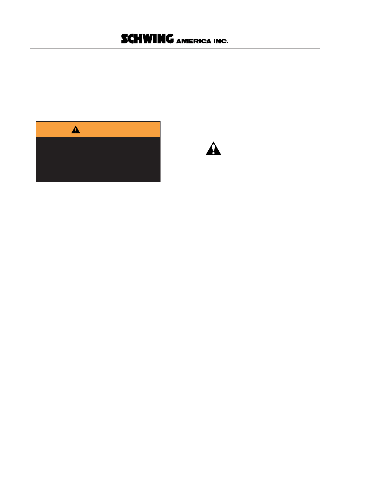
Safety alert symbol and signal word
explanation
The triangle with the exclamation point inside is used
to alert you to an important safety point and is called a
safety alert symbol
. One of the following signal words
will appear after the safety alert symbol:
• If the safety alert symbol is followed by the signal
word
DANGER
, it indicates a hazardous situation
which, if not avoided,
WILL
lead to
death or
serious injury.
• If the safety alert symbol is followed by the signal
word
WARNING
, it indicates a potentially
hazardous situation which, if not avoided,
COULD
result in
death or serious injury.
• If the safety alert symbol is followed by the signal
word
CAUTION
, it indicates a potentially
hazardous situation which, if not avoided,
MAY
result in
minor to moderate injury.
• The signal word
CAUTION
used without the
safety alert symbol means the point addresses a
hazard which
COULD
cause
damage to
equipment or property.
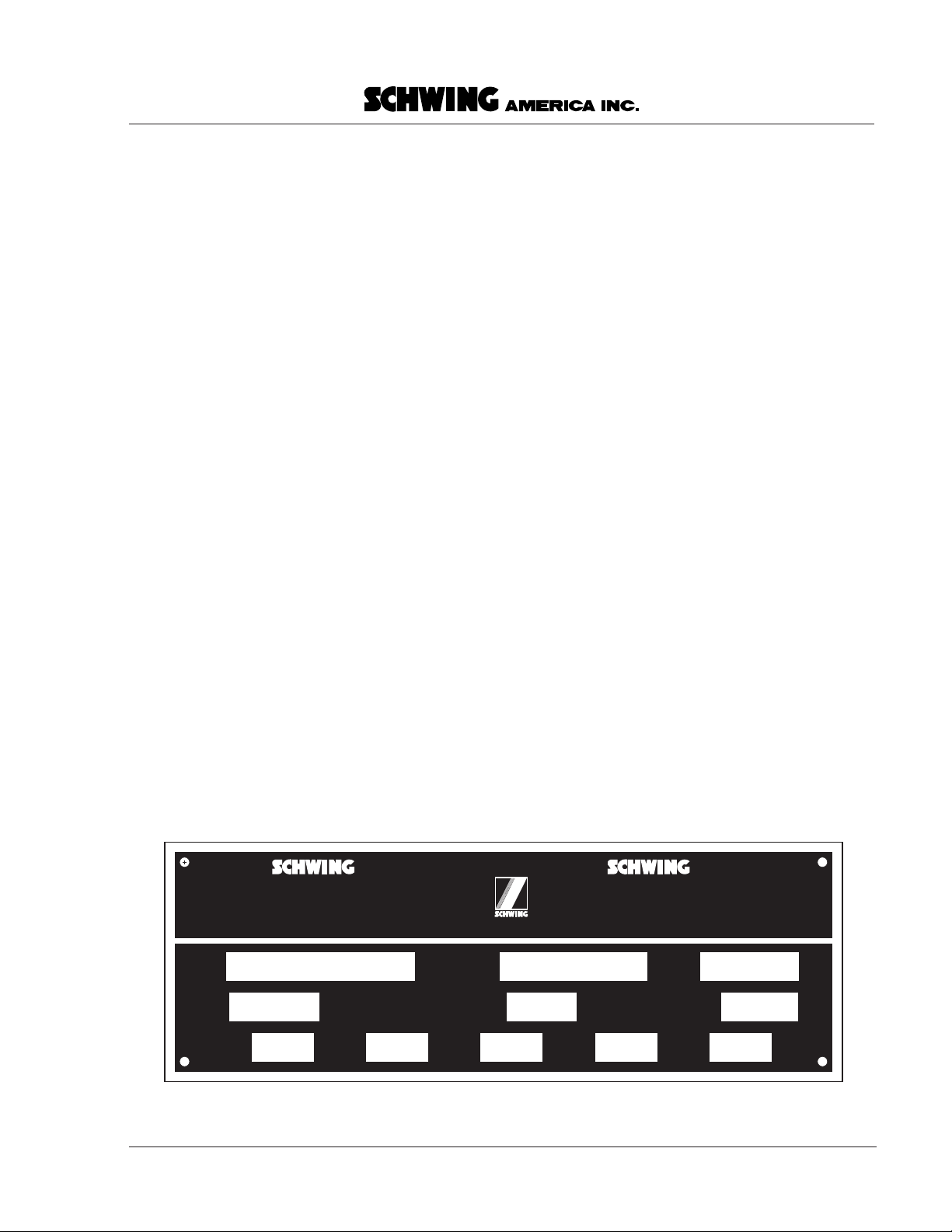
Warnings have been placed in the text where needed.
Additional information used with the signal words is
printed in decal format, as shown below, to explain the
specific hazard. Occasionally
bold
text is used in
addition to the decal for emphasis.
All persons working near the concrete pump unit must
be able to recognize hazardous situations. They must
know how to avoid these situations and how to react
quickly and appropriately whenever hazardous
situations arise.
Heed the warnings shown on the decals!
WARNING
Improper setup / operation creates
hazards. Do not operate this machine
without training. Understand the
warnings in safety manuals and on
decals.
000099.eps
Danger
Warning
Caution