CertainTeed TrueComfort User manual

Blown-in Fiber Glass Insulation System
CertainTeed
OPERATOR’S MANUAL
Tr ueComfort
Blown-in Fiber Glass Insulation
Aislamiento de fibra de vidrio por soplado
®

2
TrueComfort®System
Table of Contents
Introduction 3
Safety 4
Specifications 7
Features 8
Setup and Operation 12
Generators and Extension Cords 17
Electrical Diagram 18
Troubleshooting 19
Customer Service and Replacement Parts 25
Claims, Damage or Loss 26
Warranty Claims 27
Insulation Terms and Values 28
Warranty 29
Contents

3
Introduction
TrueComfort System
Introduction
TrueComfort®Blown-in Fiber Glass Insulation System
CertainTeed’s TrueComfort®Blown-in Fiber Glass Insulation System is designed for use by do-it-yourselfers
and remodeling contractors. The system is comprised of CertainTeed’s high-quality blown-in insulation and the
portable blowing machine used to install it.
The TrueComfort machine has a two-piece design, making it easy to transport in a minivan or SUV. Other features
include a remote control on the hose that allows the user to turn the machine off and on while in the attic, and an
easy-to-maneuver hand-truck design.
TrueComfort insulation is a safe, blown-in fiber glass product specially designed for attic applications.
It is super-expanding, so it requires fewer bags than similar products to achieve the same R-value.
The TrueComfort insulation and high-performance blowing machine combine to form an insulating system
offering superb performance, dependability and ease of use.
About CertainTeed Corporation
Through innovation and creative product design, CertainTeed has helped to shape the building products
industry for more than 100 years. The company is North America’s leading brand of exterior and interior
building products, including insulation, roofing, siding, windows, fence, decking, railing, trim, foundations,
pipe, walls, ceilings and access covers. Headquartered in Valley Forge, Pennsylvania, CertainTeed has
nearly 70 manufacturing facilities throughout the United States and Canada.
About this Manual
Please read this manual thoroughly before operating the TrueComfort Blown-in Fiber Glass Insulation System. All
of the features, setup and operation procedures, specifications and warranty information, as well as instructions
for the safe operation of the portable blowing machine, are detailed for your information and convenience.
Thank you for choosing the TrueComfort System.

4
Safety
TrueComfort System
Safety
IMPORTANT SAFETY INSTRUCTIONS
WARNING – When using electric appliances, basic precautions should always be followed,
including the following:
• Read all the instructions before using the insulation blower.
• To reduce the risk of injury, close supervision is necessary when an insulation blower is used near children.
• Do not make contact with moving parts.
• Only use attachments recommended or sold by the manufacturer.
• Use of extension and power cord:
– This product requires the use of a power cord. In addition to the supplied power cord, care should be
exercised in the selection and use of an extension cord.
– To disconnect, press the stop button and turn off the main circuit breaker before removing plug from outlet.
– Do not unplug by pulling on the power cord. To unplug, grasp the plug, rotate counter-clockwise, and pull.
– Unplug from outlet when not in use and before servicing or cleaning.
– Do not operate any insulation blower with a damaged cord or plug, or after the machine malfunctions or is
dropped or damaged in any manner. Return the insulation blower to the nearest authorized service facility
for examination, repair, or electrical or mechanical adjustment.
– The marked electrical rating of the extension cord shall be rated for at least 15 amps.
– The extension cord shall be a grounded 3-wire cord.
– The extension cord should be arranged so that it will not drape over the countertop or tabletop where it can
be tripped over, snagged, or pulled on unintentionally (especially by children).
– An outdoor rated extension cord should be used with this machine. An outdoor use extension cord is
marked with suffix letter “W” and with a tag stating “Suitable for Use with Outdoor Appliances.”
• Store insulation blower indoors when not in use. Keep out of the reach of children.
• Never operate this equipment if the operator or the machine is standing in water, snow or rain.
– Do not clean this insulation blower with water spray or the like.
• Connect to a properly grounded outlet only. See Grounding Instructions.
SAVE THESE INSTRUCTIONS

5
Safety
GROUNDING INSTRUCTIONS
This machine must be grounded. In the event of malfunction or breakdown, grounding provides a path of least
resistance for electric current to reduce the risk of electric shock. This machine is equipped with a power cord
having an equipment grounding conductor and a grounding plug. The plug must be plugged into an appropriate
outlet that is properly installed and grounded in accordance with all local codes and ordinances.
DANGER – Improper connection of the equipment grounding conductor can result in a risk of electric shock.
The conductor with insulation having an outer surface that is green – with or without yellow stripes – is the
equipment grounding conductor. If repair or replacement of the cord or plug is necessary, do not connect the
equipment grounding conductor to a live terminal.
Check with a qualified electrician or serviceman if the grounding instructions are not completely understood,
or if in doubt as to whether the machine is properly grounded. Do not modify the plug provided with the machine
– if it will not fit the outlet, have a proper outlet installed by a qualified electrician.
This machine is for use on a circuit having a nominal rating no more than 120 VAC, and is factory equipped with
a specific electric plug. No adapter should be used with this machine. If the machine must be reconnected for
use on a different type of electric circuit, the reconnection should be made by qualified service personnel.
After the reconnection, the machine should comply with all local codes and ordinances.
Grounding Pin
Grounding Pin
Grounding Mean
Adapter
Metal Screw
Cover of Grounded
Outlet Box

6
TrueComfort System
Safety continued
When working with insulation, always wear a long-sleeved shirt, gloves, a hat, goggles or safety glasses
for eye protection. Use 3M brand #8710 nose/mouth dust mask (or equivalent) for respiratory protection.
Safety rules:
• Do not operate the machine without the hopper rmly attached to the base.
• Always use the supplied power cord with this machine at all times.
• Never reach into the hopper while operating.
• Rotating agitator blades can cause severe injury. Stop all motors and disconnect the power cord before
attempting to remove any foreign object or jam.
• Never operate this equipment if the operator or the machine is standing in water, snow or rain.
• Never point insulation hose in the direction of people or pets.
• Do not operate this equipment when minors are present or leave unattended.
Always disconnect power from machine before leaving unattended.
SYMBOLS
The following signal words and meanings are intended to explain
the levels of risk associated with the use of the TrueComfort System.
SYMBOL SIGNAL MEANING
DANGER Indicates an immediate hazardous situation which,
if not avoided, will result in death or serious injury.
WARNING Indicates a potentially hazardous situation which,
if not avoided, could result in death or serious injury.
CAUTION Indicates a potentially hazardous situation which,
if not avoided, may result in minor or moderate injury.
Safety
SERVICE:
Servicing requires extreme care and knowledge
and should be performed only by a qualified
service technician. For service, we suggest you
return the product to the nearest AUTHORIZED
SERVICE CENTER for repair. When servicing,
use only original equipment replacement parts.
WARNING:
Servicing requires extreme care and knowledge
and should be performed only by a qualified
service technician. For service, we suggest you
return the product to the nearest AUTHORIZED
SERVICE CENTER for repair. When servicing,
use only original equipment replacement parts.
WARNING:
The operation of any blowing insulation products can result in foreign objects being thrown into your eyes,
which can result in severe eye damage. Before beginning operation, always wear safety goggles or safety
glasses with side shields and a full face shield when needed. We recommend Wide Vision Safety Mask for
use over eyeglasses or standard safety glasses with side shields. Always wear eye protection that marked
to comply with ANSI Z87.1.

7
Specifications
TrueComfort System
Specifications
Weight (machine only)..................................................................................................... 142 lbs/64.40 kg
Weight (shipping)........................................................................................................... 222 lbs/100.70 kg
Hopper .............................................................................................................................. 23 lbs/10.43 kg
Base (assembly).............................................................................................................. 119 lbs/53.97 kg
Power cord, 50"...................................................................................................................... 9 lbs/4.08 kg
Dimensions:
Height ...................................................................................................................................... 54"/137 cm
Width..................................................................................................................................29-1/4"/74.3 cm
Length (base).....................................................................................................................28-1/8"/71.4 cm
Mechanical:
Blower (single stage) ...........................................................................145 cfm/2.8 psi/4.08 m3/0.193 bar
Gear motor......................................................................................................................246 hp @ 54 rpm
Gear motor torque .........................................................................................................................306 in/lb
Drive chain ....................................................................................................................... #35 ASME/ANSI
Electrical ..............................................................................................115VAC @ 13.5 amps/1552 watts
Power cord, type SJO (twist lock).......................................................................... 14/3 x 50/15.24 meters
Hose w/wireless remote control ......................................................... 2-1/2" x 50'/63.5 mm x 15.24 meter
Wireless remote (range) ...................................................................................................250'/76.2 meters
Wheels ......................................................................................................................................10"/254mm
Other:
Warranty.............................................................................................................18 months (parts & labor)
Production......................................................................................................6-7 lbs/min/2.73-3.17kg/min
54"
44"
22"
29 1/4" 34 1/2"
28 1/8"
Specifications are subject to change without notice.
32"

8
TrueComfort System
Features
This TrueComfort insulation machine is equipped with the following features. Before using this machine,
familiarize yourself with all the operating features and safety requirements. However, do not let familiarity
with this machine make you careless.
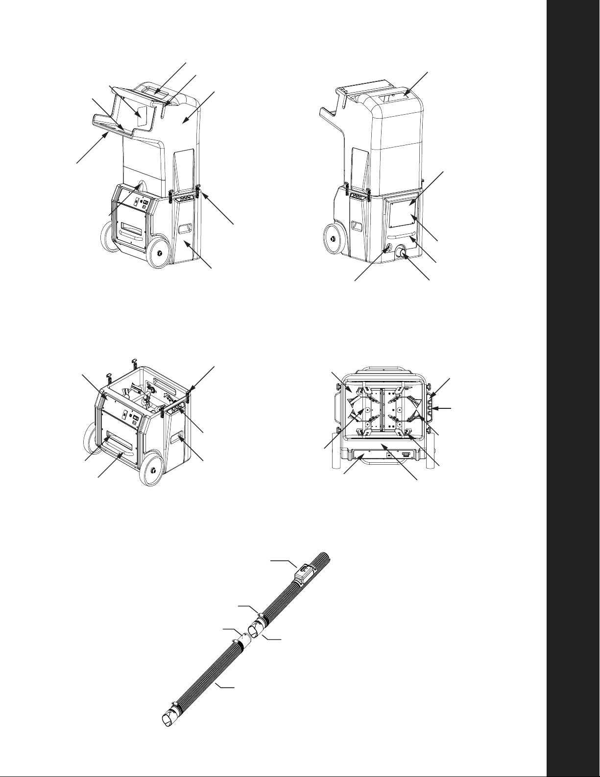
• Hopper (Fig 1) The top part of the machine which
has a built-in loading tray and contains the fiber glass
insulation. Note the key slot on the bottom right side of
the hopper that matches the key feature in the machine’s
base when assembled properly (Fig 4).
• Base (Fig 1) The lower part of the machine which
houses the rotating agitator blades, agitator motor,
blower motor, drive components and electrical system.
Note the base’s key feature on the side by the operator
panel; this key feature goes into the hoppers key slot
when assembled properly (Fig 4).
• Magnet, Safety Interlock (Fig 1) Located in both the
hopper and base components and is part of the safety
of this machine.
• Hopper Latch (Fig 1) Located on both the hopper
and base with a total of four latches. The latches
secure the hopper and base together for normal
operation.
• Bag Cutting Slot (Fig 1) This feature is molded into
the hopper and is used to assist in guiding the knife
when opening the bag.
• Knife Holding Tray (Fig 1) This feature is molded
into the hopper and should be used to hold the knife
when not in use.
• Window (Fig 1) There are two windows in the hopper.
These windows allow the operator to observe the flow
of material and assist in determining when to load the
next half bag of fiber glass insulation.
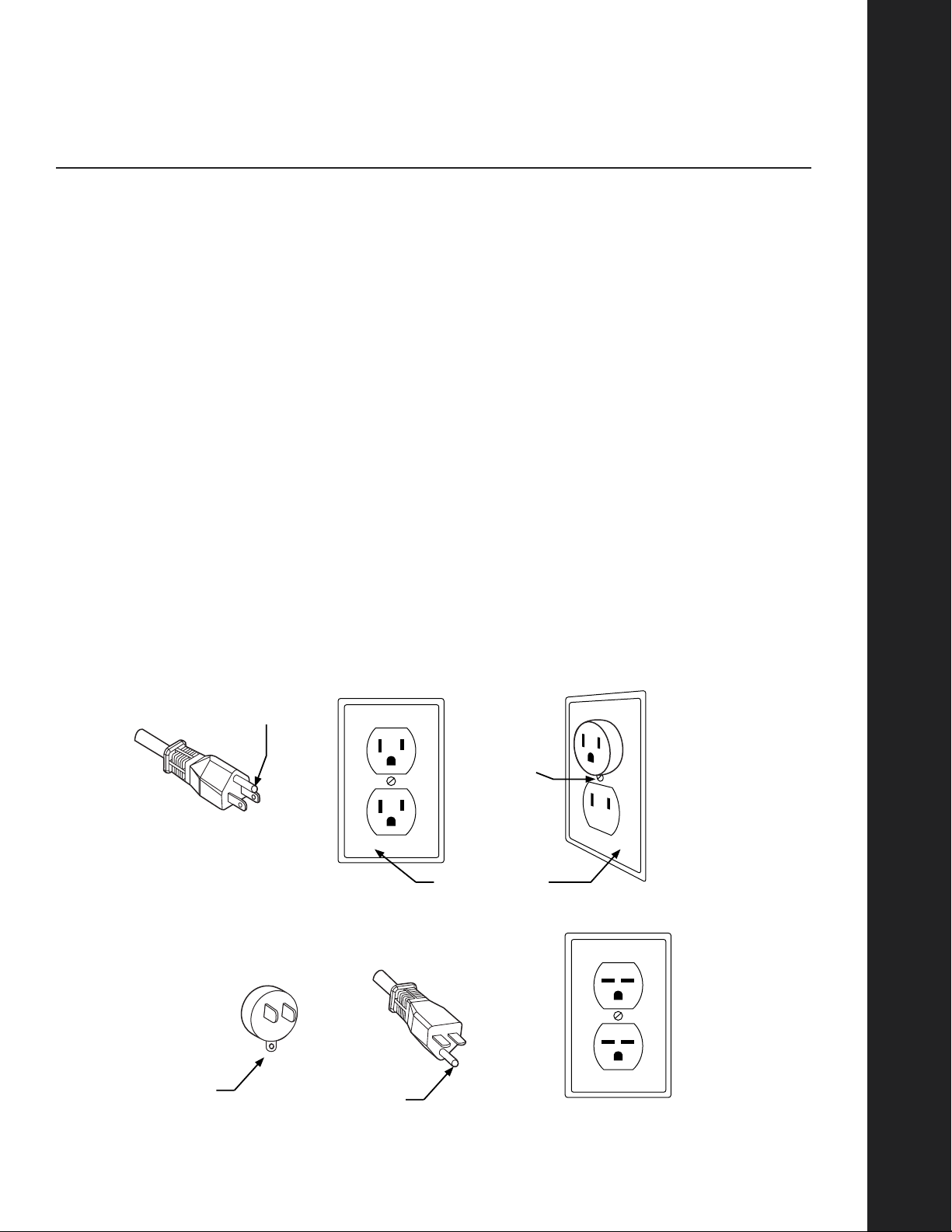
• Electrical Inlet (Fig 2) Located in the base of the
machine and where the power cord is to be plugged in.
Always plug this machine into 115 volt circuit rated at
15 amperes. Use only the supplied power cord.
• 2.5" Hose Outlet (Fig 2) Located in the base and
where the insulation hose is to be attached using the
quick connect feature.
• Handle(s) (Fig 2-3) There are a total of four handles
located in the base, two of which are molded into
the base and two others which are attached. These
handles are to be used for lifting the base in and out
of the transportation vehicle. These handles are not
intended for securing the base during transportation.
• Access Panel (Fig 2) This is located in the base
and is an access cover for the following; 2.5" outlet
interconnect, agitator bearings, electrical connections
and serial number.
• Electrical Panel (Fig 3) This panel is mounted to
the base and houses the following: time delay relay,
blower relay, main circuit breaker, agitator circuit
breaker, GFCI, hour meter.
• Operator Panel (Fig 3) This panel is mounted to the
base and houses the following: “on” / “off” switches
for operation of the entire machine and the ready light.
(Not shown)
• Agitator Basin (Fig 4): This is part of the base and
houses the rotating agitators. It also has an opening
at the bottom which allows the insulation to flow into
the airlock.
• Agitator(s) (Fig 4) There are two agitators located
within the base. They rotate at a moderate speed
to condition the fiber glass insulation material to the
desired density.
• Agitator Paddles (Fig 4) These are located on the
agitator within the base. They are attached to each
agitator blade and are made of rubber. There are two
different styles to help facilitate both the conditioning
and production of the fiber glass insulation material.
• Airlock (Fig 4) Located in the bottom of the base and
below the agitator(s). This part of the system is used to
meter the proper amount of conditioned insulation into
the air stream of the blowing hose.
• 2.5" Hose (Fig 5) This is a separate part of the
system which attaches to the outlet of the base. The
TrueComfort machine is supplied with two 50' sections
of blowing hose. The two sections can be coupled –
for a total of 100’ – using supplied couplings.
Features

9
Features
Wireless Remote Holder
2.5" Hose Clamp
2.5" Hose
2.5" Hose Connector
Quick Connect
Fig. 5
Knife Holding Tray
Window
Handles
Magnet
(safety interlock)
Holding Tray
Bag Cutting Slot
Hopper
Hopper Latch
Base
Fig. 1
Serial Number
(behind access panel)
Access Panel
Handle
2.5" Hose Outlet
Electrical Inlet
(twist lock)
Fig. 2
Window
Electrical
Panel
Hopper Latch
Operator
Panel
Handle
Handle
Fig. 3
Filter
Agitator Basin
Agitator
Airlock
Agitator Paddles
Operator
Panel
Hopper to base “key”
alignment feature
Electrical Panel
Fig. 4
Proximity Sensor
(not shown)

10
TrueComfort System
Features continued
• GFCI (Ground Fault Circuit Interrupter) (Fig 6)
A GFCI operates on the principle of monitoring the
imbalance of current between the circuit’s ungrounded
(hot) and grounded (neutral) conductor. It does not
monitor the grounding conductor, and so it will still
operate in a circuit without a ground.
• Agitator Circuit Breaker (Fig 6) The circuit breaker
automatically opens and protects the entire machine
from damage caused by overloading the agitator/
airlock components, low voltage, short circuits or
dropping foreign objects into the hopper/base.
• Main Circuit Breaker (Fig 6) The circuit breaker
automatically opens and protects the entire machine
from damage caused by overloading the machine, low
voltage, short circuits or dropping foreign objects into
the hopper/base.
• Hour Meter (Fig 6) Displays the total number of
hours used. It is also used to indicate when regular
preventive maintenance is due.
•“On” Button (Fig 7) This push button switch is
colored green and turns the entire machine “on.”
•Ready Light (Fig 7) This white indicator light allows
the operator to visually see when the machine is ready
to use. It will not illuminate if the following conditions
exist: agitator or main circuit breaker is tripped or is
not depressed in the “on” position, GFCI is tripped or
electrical power is not present at the electrical inlet of
the machine.
• “Off” Button (Fig 7) This push button switch is
colored red and turns the entire machine “off.”
This switch also can be used in an emergency and
overrides the wireless remote.
• Wireless Remote & Holder (Fig 8) This feature is
part of the control system and allows the operator
in the attic to turn “on” and “off” the machine via a
wireless signal. The green push button turns on the
entire machine and the red push button turns it off.
The indicator light at the top of the wireless control will
illuminate when either button is depressed, signifying
that the batteries are in good condition and the signal
has been sent to the machine on the ground.
The wireless control can operate up to 250' depending
upon the location of the machine and the construction
of the structure being insulated. If you experience
difficulties with the wireless system, you may need to
change the batteries in the transmitter or locate the
machine to another area where the signal is better.
The transmitter (attached to the hose) uses two (2) AA
batteries. To replace the batteries, the holder must be
removed from the hose.
Features

11
Features
Note: The wireless system is made up of
two different components: A = Transmitter,
which is attached to the hose, B = Receiver,
which is housed within the base of the machine.
Wireless Remote & Holder
Fig 8
Battery
Indicator
ON Button
(green)
OFF Button
(red)
Agitator
Circuit Breaker
GFCI Hour Meter
Fig. 6
Electrical Panel
Operating Instructions
Machine
Circuit Breaker
Ready Light
On Push
Button
Off Push
Button
Fig. 7
Operator Panel

12
Setup and Operation
TrueComfort System
Setup and Operation
SETUP
Before the machine will operate, the hopper must be oriented and securely fastened as shown (Fig 9-10).
Next, attach the two 50', 2.5" sections of hose to each other, then to the machine – using the quick connect
(Fig 10). Attach additional sections of hose using the supplied hose connector and hose clamp.
NOTE: You may only connect up to a maximum of 100' of hose.
Attach the special (twist lock) power cord to the electrical inlet by aligning the blades and twisting in a clockwise
motion until it stops. Plug the other end of the power cord into a dedicated 115 VAC 15 amp grounded outlet.
Refrigerator or freezer outlets usually fit the requirements. If necessary, these appliances can be temporarily
unplugged, enabling the TrueComfort machine to run on sufficient power.
Note: Never transport the
machine in an open truck while
hopper is attached. Failure to follow
this warning may cause the hopper
to come off while driving.
Use a 115 VAC 15 amp
household outlet
Fig. 9
Fig. 10
Electrical Inlet
(twist lock)

13
At this point you should have the hopper attached, a 50' power cord plugged into the machine and a 115 VAC 15
amp household outlet, and 100' of 2.5" blowing hose attached to the outlet of the machine.
Note: The attic should be prepared before any insulation is added.
Contact your local building code department for further details.
Next, run the 100' of 2.5" hose into the attic and to the furthest point. Next, locate the circuit breaker on the base
of the machine and depress to the “on” position (Fig 11). Once the main circuit breaker has been depressed the
“READY LIGHT” on the operator panel will illuminate indicating the machine is ready for use (Fig 12).
NOTE: If the ready light does not illuminate, check to make sure the hopper is on correctly and the power cord is
supplying power to the machine. When power is present the LED will illuminate.
SET-UP IS COMPLETE AT THIS POINT
OPERATION
Operator Panel
The electrical control of the TrueComfort machine has been designed with the latest technology to allow the
operator full control of the machine at either the ground or in the attic. The operator panel has two push buttons
for the “on”/ “off” function and a ready light to let the operator know when the machine is ready for use (Fig
13). When the green push button is depressed it will first start the blower, then 3-5 seconds later it will start the
agitator. To stop the entire machine (blower and agitator), depress the red button.
NOTE: You cannot run the blower or agitator independently of each other!
Setup and Operation
Note: If the ready light is not illuminated,
the machine will not operate before these conditions
are corrected:
• Hopper is attached correctly.
• Machine circuit breaker turned on.
• Agitator circuit breaker reset.
• Power cord is plugged in.
Fig. 12
Ready Light
Ready Light
Fig. 11
Machine Circuit Breaker
Fig. 13
Ready LightOperator Panel
On (Green) Off (Red)

14
Setup and Operation
TrueComfort System
Setup and Operation continued
Wireless Remote
The wireless control of the TrueComfort machine is designed to allow the attic operator full control of the machine
while in the attic. The wireless transmitter and housing are attached to the 2.5" blowing hose and can operate up
to a distance of 250'.
Depress the green “on” button to start the blower and agitator. First the blower will start, then 3-5 seconds later
the agitator will start. To stop the machine (blower and agitator), depress the red button.
Note: You cannot operate each motor independently.
Note: The battery indicator on the
wireless transmitter will flicker when either
button is depressed. If the battery indicator
does not flicker and/or the machine is not
responding, check or replace the batteries.
For replacement batteries, use two (2) AA.
Battery
Indicator
ON Button
(green)
OFF Button
(red)
Wireless Remote

15
LOADING THE MACHINE
Always use caution when cutting bag open.
Using a long-bladed knife, cut packages in half according to the instructions on the package. Cut about one-
quarter of your total number of packages to start, and stack the rest near the machine for easy access (Fig 14).
The process of feeding insulation into the blowing machine is fairly simple, but there are a couple of key points
to be aware of when loading.
Place one of the package halves onto the hopper tray (Fig 15-16) and align the green dotted line with the knife
slot. It’s important to note that the open part of the bag should be facing to the left or right and never into the
hopper; when positioned this way, the arrows will point into the hopper and the green dotted line will match up
with the knife slot. Remember: NEVER position the open end of the half-package facing into the hopper.
Setup and Operation
Fig. 14
Knife Slot
Green
Dotted line
Alignment arrows
Fig. 15 Fig. 16

16
Setup and Operation
TrueComfort System
Setup and Operation continued
Insert the knife into the slot and slit quickly across the entire package from left to right (Fig 17-18). Be aware
that the compressed insulation will expand quickly into the hopper opening. It is best if material feeds into the
machine evenly.
While feeding the insulation into the machine, pull the bag out. DO NOT LET THE BAG FALL INTO THE
MACHINE. DO NOT OVERLOAD/STUFF THE MACHINE, or it will shut off. Feed the next half-package into
the machine when you can see the “add more” line inside the hopper. Repeat the above steps until the job is
complete.
Note: Periodically, it may be necessary to push or nudge the insulation sitting on the shelf into the hopper.
Additional troubleshooting information can be found beginning on page 19.
Note: The amount of insulation you blow into the attic depends on the R-value, or level of
insulating performance you wish to achieve. The higher the R-value number, the better the thermal
performance – and the thicker the layer of TrueComfort insulation, the higher the R-value will be.
Fig. 18
Fig. 17
Top View

17
TrueComfort System
Generators and Extension Cords
The TrueComfort System will operate on power from a commercial-sized generator. No household generators
should be used due to the high inrush requirements of the TrueComfort System. Also, generators made by
Honda, Yamaha, Coleman and Generac are not recommended. While they are of high quality, these generators
do not have the inrush protection devices necessary to start the TrueComfort System and protect the generator.
The start-up requirement for a TrueComfort System is 3450 watts; normal operating requirement is 1725 watts.
We recommend a generator of not less than 4000 watts, 115 VAC.
In addition, CertainTeed recommends generators that have a 50% power boost feature which aids the generator
in high current start-ups. Running additional equipment from the same generator will increase the total electrical
requirements. Before selecting the correct size of generator, add up all tool wattages including the TrueComfort
System. For details on selecting and purchasing a generator, please call CertainTeed Machine Works.
Note: Using a generator of insufficient size will void the Warranty.
If additional length is required – beyond the supplied 50' power cord – see table below for adding an extension
cord. Use only those extension cords meeting these specifications. Always use a 3-conductor extension cord.
Extension Cord Current Capacities
Wire AWG Max Size AMP Rating
10 AWG
100' 25
12 AWG
50" 20
Generators and Extension Cords

18
Electrical Diagram
TrueComfort System
Electrical Diagram

19
TrueComfort System
Troubleshooting
PRObLEM LIkELY CAUSE REMEDY
Machine will not start
or operate.
Main circuit breaker is tripped or is
not in the “on” position.
At electrical panel, check for tripped
circuit breaker. Reset the circuit breaker
to the “on” position.
Power cord is not receiving
electricity from electrical source.
Check for a tripped circuit breaker
at the electrical source or a loose
connection at the electrical outlet.
Check extension cord for damage,
such as cuts in outer jacket or exposed
wires. Do not use until repair is made.
Check to ensure that the power cord
connection at the electrical inlet on
machine is secure.
GFCI has tripped. At electrical panel, check for tripped
GFCI button. If tripped, the upper
button of GFCI will be “popped” out;
push to re-set.
Hopper is not correctly attached
to the base and/or is not securely
fastened.
Refer to the setup section of this
manual for correct orientation of the
hopper & base. Reattach hopper to
base using the four hopper latches.
Wireless remote does not
operate the machine.
Location of the machine. The structure which is being insulated
may be causing the signal interference.
Move the machine to another location
which may allow for a better signal
between the transmitter and the
receiver.
Batteries within the transmitter may
be weak and need to be replaced.
The transmitter has a built-in indicator
light which, when depressed, causes
the indicator to illuminate. If the
indicator light does not light up,
batteries may be weak and need to be
replaced. Use two (2) AA batteries.
Troubleshooting

20
TrueComfort System
Troubleshooting continued
PRObLEM LIkELY CAUSE REMEDY
Low production, insulation drips
out the end of the hose. Not
getting proper arc length.
Too many tight bends or a kink in
the hose.
When properly setup, the hose should
be as straight as possible to ensure a
smooth flow of material. Straighten out
any tight bends or kinks in the hose.
Worn seals in airlock. Replace seals in airlock section of the
base. Minimum psi = 2.0.
Hose is too long. The machine is supplied with 100'
foot mark of hose. If additional hose
length was added, remove hose added
beyond 100' foot mark.
Hose connections may be leaking. Check the connection between the
2.5" hose outlet and quick hose
connect. Minimum psi = 2.0. It may be
necessary to replace one or all of the
components to correct air leakage.
Insulation drips out the end
of the hose. Not getting proper
arc length.
Foreign object in airlock or hose. Disconnect power cord at
the machine. Remove hopper and
insulation from the base. Visually
inspect agitator and airlock for any
foreign objects. Also, check hose for
any foreign objects.
Troubleshooting
Other manuals for TrueComfort
1
Table of contents
Other CertainTeed Construction Equipment manuals
Popular Construction Equipment manuals by other brands

Lonking
Lonking CDM835EV.00I Operation manual

E-Z DRILL
E-Z DRILL 20 UTL maintenance

Skylift
Skylift Mini-Derrick Super 6000 Low Pro Parts and maintenance manual

Husqvarna
Husqvarna DS 150 Operator's manual

HYVA
HYVA HC801 WARNING, OPERATING AND MAINTENANCE MANUAL

JEKKO
JEKKO SPD265C+ Operating and maintenance manual

Wacker Neuson
Wacker Neuson IREN Operator's manual

Makita
Makita DVR350 instruction manual

Metro DataVac
Metro DataVac Roman-Tile Installation details

Trinity Highway
Trinity Highway QuadGuard M Wide Product Description Assembly Manual

Dynapac
Dynapac BV21 Instructions and spare parts catalogue

Facsimile
Facsimile Genius Use and maintenance manual