WARRANTY TERMS
1) Warranty period is measured as one (1) year from date of purchase.
2) In the unlikely event of product failure during normal use (as defined by this manual), the product will be repaired
or replaced free of charge, but only at the original dealer/place of purchase. Demand for onsite repairs may be met in
some cases within Japan, but onsite service fees will apply and vary by location.
3) All warranty claims must be submitted through the vendor from whom you originally purchased this product. You
must fill out the form on the front page of this manual, and submit the dated purchase receipt.
4) You can only submit warranty claims to us if you have moved and can no longer visit your HV-300 dealer.
5) Customer bears the cost of removal/reinstallation fees, as well as return shipping if not hand-delivered.
6) Regardless of being covered under Warranty, the following cases resulting in malfunction will require a fee:
•Oil, water, dust, etc. having accumulated inside and on the electronics.
•Improper installation or carelessness by the user.
•Unauthorized product repair or modification.
•Accidental drops, falls or other strong impact.
•Fire, earthquake, flood, lightening, tornadoes, other natural disasters, as well as pollution, salt-air damage, etc.
•When used outside the intended use, as specified in this manual.
•Car accidents, vandalism or theft.
• Problems due to deficiencies in this manual, or if you do something this manual doesn’t specifically prohibit.
•And cases where you do not properly fill out your claim, provide false info., and/or lack a dated receipt.
7) This warranty is only valid for HV-300 users outside Japan with express written approval from KIRAMEK.
8) We cannot reissue printed documents free of charge. Please keep this document safe and do not lose it.
Product repair or replacement is guaranteed under the terms, conditions and duration of this warranty. This warranty
does not limit your legal rights. If you have questions or problems after this one (1) year warranty has expired, please
consult with the original dealer from whom you purchased the HV-300 product.
Because your warranty claim will be invalidated by an improperly filled out PRODUCT WARRANTY CLAIM card,
please carefully confirm all entries and/or consult with your HV-300 dealer before submission.
PLEASE NOTE:
DIP Switch #6 must be used as shown below to enable the HV-300 to function on
the chosen car. (DIP Switches #1 ~ #5 should have been set for your car in Step-1.)
NOTE: When the above steps are finished, you never need to do them again for
the same car, even if you disconnect the OBD plug, change your car’s battery, etc.
But if you move the HV-300 to a different compatible car, you need to repeat the
above steps.
1
ON
2 3 4 5 6
Turn on the Ignition.
Make sure all 3 connectors are plugged into the Controller.
(2 for Disable Switch, 1 for OBD Harness)
Flip DIP SW #6 to ON.
6
Flip DIP SW #6 to OFF.
6
FINAL SETUP
3
OBD plug: choosing which side wires exit
Connect to the car’s OBD as shown above.
You can choose which
side the wires exit.
HV-300 WIRE HARNESS
OBD PIN-OUTS
Color Description
+12V
GND
CAN-HI
CAN-LO
RED
BLK
BRN
BRN/RED
pin16pin14
CAN-LO +12V
GROUND CAN-HI
pin6pin4
OBD CONNECTION
2
9
1
9
1
If you already used the
included wire-tie, you will
need to remove it so you
can slide off the OBD cap. NOTE: When finished, secure
the wires to the tab on the
cap using a small wire-tie.
Slide off the
cap as shown.
Pull wires to the opposite
side and put cap on
as shown.
9
1
NOTE: If the vehicle’s OBD plug is already being used or if there is no space to
attach the HV-300’s OBD plug, you can either purchase our optional OB-22
extender harness, or you can purchase our Posi-Tap connector 4-pack (p/n
NT-4.) We don’t recommend soldered connections. You would be surprised
to know how many badly soldered connections result in problems!
4-STEP INSTALLATION
Connect the HV-300’s OBD2 plug to the car’s OBD2 plug.
2
Set vehicle compatibility DIP switch to match your car.
Use DIP SW#6 to confirm CAN signal compatibility.
Refer to “DIP SWITCH SETUP” below.
Refer to “OBD CONNECTION” below.
Refer to “FINAL SETUP” below.
1
3
Mount the Control Module and Disable Switch.
Refer to “MOUNTING CONTROLLER & DISABLE SW” below.
4
DIP SWITCHES
The location of the DIP switches is shown in the
diagram at right.
All switches are set to OFF (all UP) by default,
as shown:
DIP SWITCH SETUP
1
1
ON
2 3 4 5 6
SW4
SW3
SW2
SW1
DIP
SW No. FUNCTION
No function. Do not touch. Leave set to OFF state.
Backing Alert Beep Length
Backing Alert Function
Speed-Lock Function
UNLOCK Trigger
One-time use only switch. See “FINAL SETUP” below.
SW5
SW6
OFF = Short Beep
ON = Long Beep
OFF = Enabled
ON = Disabled
OFF = Enabled
ON = Disabled
OFF = “P” Gear
ON = Ignition OFF
After completing Steps 1~3, mount the HV-300 controller as shown.
Ensure it does not interfere with foot pedals or the car’s moving parts.
Mount the Disable Switch with the included 2-sided tape whereever you
can conveniently push the button and view the LED.
MOUNTING CONTROLLER & DISABLE SW
4
Driver’s Kick Panel
Area above driver’s kick panel
WARNING! This product is not waterproof or dust-proof. Never install in the engine
compartment. Never install where water can pool or where oil, dirt and grime could
enter and cause an electrical short.
Location shown at left
is simply one recom-
mended location for
the controller. Use
wire-ties to mount the
controller. Never
obstruct foot pedals or
other vehicle parts!
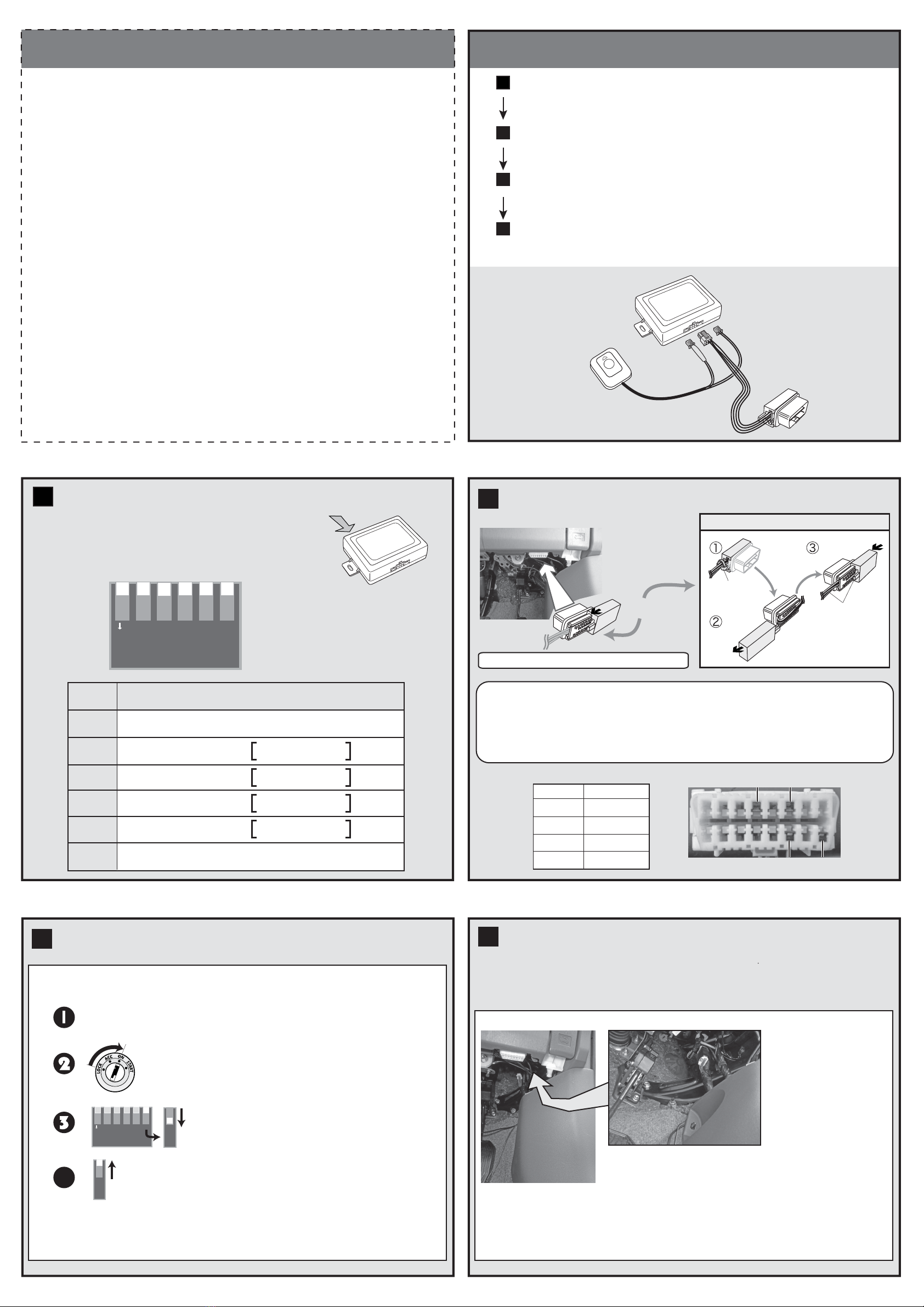
INCLUDED PARTS
Controller
Disable Switch
with LED
OBD
Harness
Harness Length: 1m
Harness
Length: 1m
4


