SciCan BRAVO G4 17 User manual

BRAVO G4
Chamber Autoclave
™
SD-601 EU ML R1 | 97055159 Rev. 2
BRAVO is atrademark of SciCan Ltd. A Coltene Group company.
Operator’s Manual

Distributed by :
SciCan Ltd.
A Coltene Group Company
1440 Don Mills Rd.,
Toronto, ON, Canada, M3B 3P9
T +1-416-445-1600
TF +1-800-667-7733
customerservi[email protected]m
Manufactured by:
CEFLA s.c.
Headquarter: Via Selice Provinciale 23/A
40026 Imola (BO) IT
EN

Bravo G4 17 / Bravo G4 22 / Bravo G4 28
2
.
Contents
1. FOREWORD.................................................................................................................................................................................................... 4
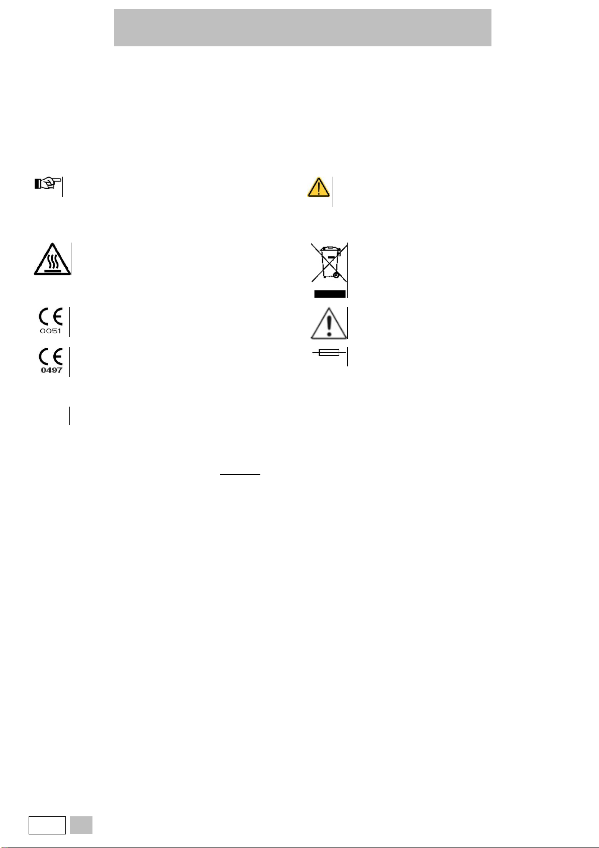
1.1. SYMBOLS USED........................................................................................................................................................................................4
1.2. SYMBOLS ON THE DEVICE ......................................................................................................................................................................4
1.3. RELEVANT EUROPEAN DIRECTIVES ......................................................................................................................................................4
1.4. CLASSIFICATION.......................................................................................................................................................................................4
1.5. INTENDED USE .........................................................................................................................................................................................5
1.5.1. IMPORTANT NOTES.........................................................................................................................................................................5
1.6. GENERAL WARNINGS...............................................................................................................................................................................5
1.7. RESIDUAL RISKS.......................................................................................................................................................................................6
1.8. INFORMATION ON MITIGATION OF RESIDUAL RISKS ...........................................................................................................................6
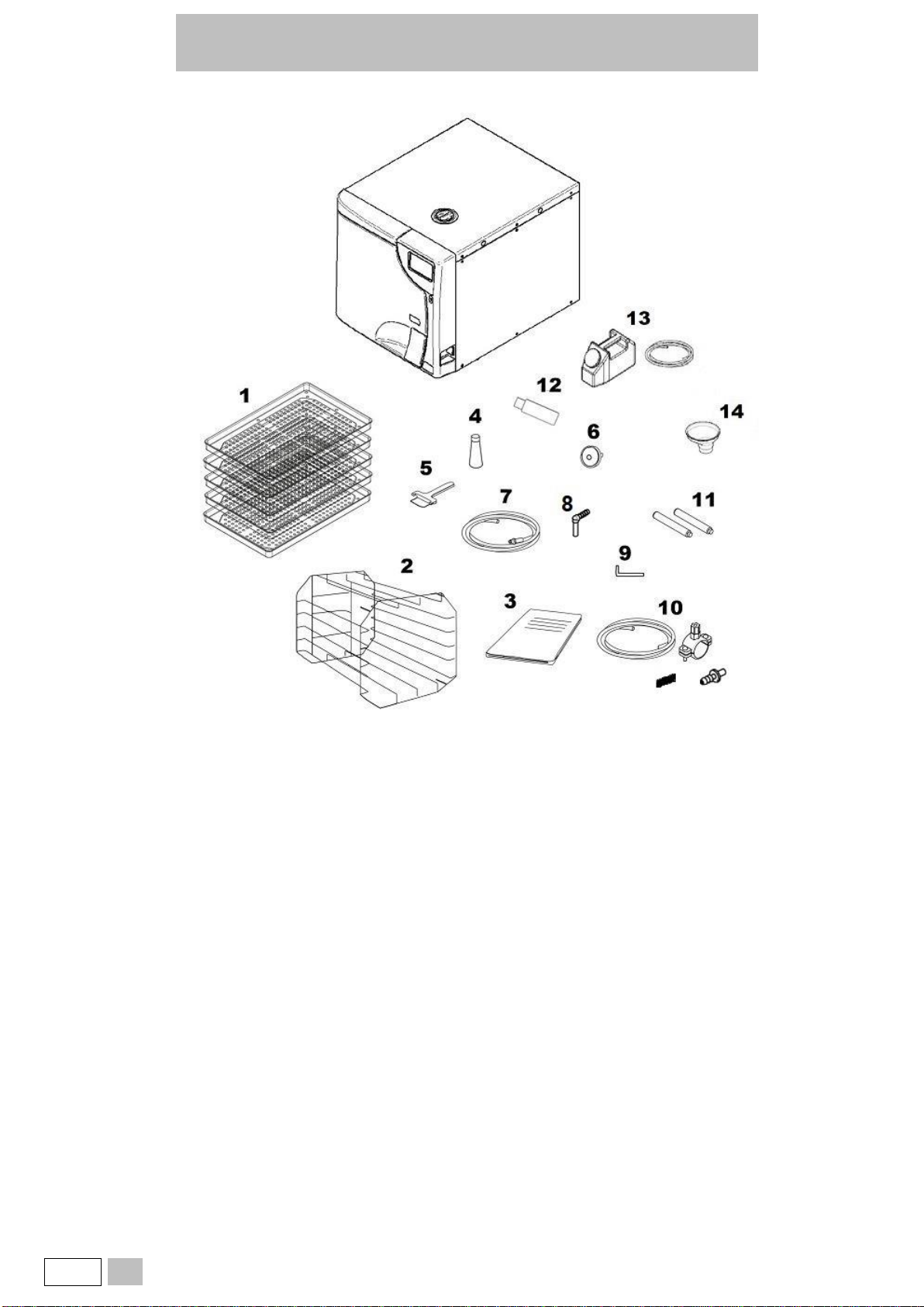
2. PACKAGE CONTENT..................................................................................................................................................................................... 7
2.1. DIMENSION AND WEIGHT ........................................................................................................................................................................7
2.2. DESCRIPTION OF THE CONTENT............................................................................................................................................................8
2.3. PRODUCT HANDLING...............................................................................................................................................................................9
2.4. CONDITIONS FOR STORAGE AND TRANSPORT....................................................................................................................................9
3. GENERAL DESCRIPTION - PRODUCT PRESENTATION............................................................................................................................ 10
3.1. GENERAL CHARACTERISTICS...............................................................................................................................................................10
3.2. TECHNICAL SPECIFICATIONS ...............................................................................................................................................................11
3.2.1. SUMMARY TABLE...........................................................................................................................................................................11
3.3. SAFETY DEVICES....................................................................................................................................................................................13
3.4. WATER SUPPLY CHARACTERISTICS....................................................................................................................................................14
3.5. FRONT .....................................................................................................................................................................................................15
3.6. REAR........................................................................................................................................................................................................16
3.7. LCD ICONS ..............................................................................................................................................................................................17
3.8. EXAMPLE OF WORKING CYCLE ............................................................................................................................................................18
4. SETTING UP THE DEVICE............................................................................................................................................................................ 19
4.1. OVERALL DIMENSIONS..........................................................................................................................................................................20
4.2. COMPARTMENT DIMENSIONS FOR BUILT-IN INSTALLATION.............................................................................................................21
4.3. GENERAL PRECAUTIONS FOR INSTALLATION....................................................................................................................................21
4.4. POWER SUPPLY .....................................................................................................................................................................................21
4.5. ELECTRICAL CONNECTIONS.................................................................................................................................................................22
4.6. DIRECT CONNECTION TO A CENTRALISED DRAINING POINT ...........................................................................................................22
5. FIRST START-UP.......................................................................................................................................................................................... 23
5.1. STARTING................................................................................................................................................................................................23
5.2. MAIN MENU .............................................................................................................................................................................................25
5.3. FILLING DEMINERALISED / DISTILLED WATER ....................................................................................................................................25
5.3.1. MANUAL FILLING............................................................................................................................................................................25
5.3.2. AUTOMATIC FILLING......................................................................................................................................................................25
6. CONFIGURATION......................................................................................................................................................................................... 26
6.1. SETTINGS................................................................................................................................................................................................26
6.1.1. LANGUAGE.....................................................................................................................................................................................26
6.1.2. DATE AND TIME..............................................................................................................................................................................27
6.1.3. REMINDER......................................................................................................................................................................................27
6.1.4. USERS.............................................................................................................................................................................................28
6.1.4.1. USERS LIST....................................................................................................................................................................................29
6.1.5. PREFERENCES ..............................................................................................................................................................................30
6.1.5.1. UNIT OF MEASUREMENT ..............................................................................................................................................................31
6.1.5.2. DISPLAY..........................................................................................................................................................................................31
6.1.5.3. WATER FILLING..............................................................................................................................................................................32
6.1.5.4. PREHEATING..................................................................................................................................................................................33
6.1.6. SERVICE .........................................................................................................................................................................................33
7. PREPARATION OF THE MATERIAL ............................................................................................................................................................ 34
7.1. TREATING THE MATERIAL BEFORE STERILISATION...........................................................................................................................34
7.2. ARRANGING THE LOAD..........................................................................................................................................................................35
7.3. POSITIONING AND USE OF TRAY HOLDER SUPPORT........................................................................................................................37
8. STERILISATION CYCLES............................................................................................................................................................................. 38
8.1. EXTRA DRYING.......................................................................................................................................................................................39
8.2. DELAY START..........................................................................................................................................................................................40
8.3. EXECUTION OF THE CYCLE...................................................................................................................................................................41
8.4. CYCLE OUTCOME...................................................................................................................................................................................41
8.5. DOOR OPENING AT THE END OF THE CYCLE......................................................................................................................................41
8.6. USER-DEFINED CYCLE...........................................................................................................................................................................42
9. MATERIAL STORAGE .................................................................................................................................................................................. 43
10. TEST PROGRAMS........................................................................................................................................................................................ 44
10.1. HELIX / B&D TEST CYCLE.......................................................................................................................................................................44

Bravo G4 17 / Bravo G4 22 / Bravo G4 28
EN
3
10.2. VACUUM TEST CYCLE............................................................................................................................................................................45
10.3. VACUUM TEST + HELIX TEST / B&D TEST CYCLE................................................................................................................................46
10.4. H2O TEST ................................................................................................................................................................................................46
10.5. DOOR OPENING......................................................................................................................................................................................47
10.6. MANUAL INTERRUPTION........................................................................................................................................................................48
11. USED WATER DRAIN................................................................................................................................................................................... 49
12. DATA MANAGEMENT .................................................................................................................................................................................. 50
12.1. USB MANAGEMENT................................................................................................................................................................................51
12.1.1. DIRECT DOWNLOAD......................................................................................................................................................................52
12.2. WIFI..........................................................................................................................................................................................................53
12.3. PRINTERS................................................................................................................................................................................................54
12.4. ETHERNET...............................................................................................................................................................................................55
12.5. G4 CLOUD................................................................................................................................................................................................55
13. APPENDIX –PROGRAMS............................................................................................................................................................................ 56
13.1. SUMMARY TABLE OF 17 220 V - 240 V CYCLES...................................................................................................................................57
13.2. SUMMARY TABLE OF 22 220 V - 240 V CYCLES...................................................................................................................................59
13.3. SUMMARY TABLE OF 28 220 V - 240 V CYCLES...................................................................................................................................61
13.4. STERILISATION PROGRAM DIAGRAM...................................................................................................................................................64
13.5. DIAGRAMS OF THE TEST PROGRAMMES ............................................................................................................................................66
13.6. EXAMPLES OF PRINTED REPORTS.......................................................................................................................................................67
14. APPENDIX - MAINTENANCE........................................................................................................................................................................ 68
14.1. REGULAR MAINTENANCE PROGRAMME..............................................................................................................................................68
14.2. SCHEDULED MAINTENANCE MESSAGES.............................................................................................................................................69
14.3. DESCRIPTION OF MAINTENANCE INTERVENTIONS............................................................................................................................70
14.3.1. DOOR GASKET AND THE INTERNAL PART OF THE DOOR CLEANING......................................................................................70
14.3.2. STERILISATION CHAMBER AND ACCESSORIES CLEANING ......................................................................................................70
14.3.3. EXTERNAL SURFACE CLEANING..................................................................................................................................................70
14.3.4. CHAMBER FILTER CLEANING.......................................................................................................................................................70
14.3.5. DOOR LOCK LUBRICATION...........................................................................................................................................................70
14.3.6. ANTI-DUST FILTER CLEANING......................................................................................................................................................71
14.3.7. REPLACE THE BACTERIOLOGICAL FILTER.................................................................................................................................71
14.3.8. BOILER GASKET REPLACEMENT .................................................................................................................................................71
14.4. PERIODIC STERILISER VALIDATION .....................................................................................................................................................72
14.5. DEVICE USEFUL LIFE .............................................................................................................................................................................72
14.6. DISPOSING THE EQUIPMENT WHEN NO LONGER USED....................................................................................................................72
15. APPENDIX - GENERAL PROBLEMS............................................................................................................................................................ 73
15.1. TROUBLESHOOTING ..............................................................................................................................................................................73
16. APPENDIX –ALARMS.................................................................................................................................................................................. 75
16.1. ALARM INTERVENTION ..........................................................................................................................................................................75
16.2. ALARM DURING A CYCLE.......................................................................................................................................................................75
16.3. SYSTEM RESET ......................................................................................................................................................................................75
17. ALARM CODES............................................................................................................................................................................................. 76
17.1. ERRORS (CATEGORY E)........................................................................................................................................................................76
17.2. ALARMS (CATEGORY A).........................................................................................................................................................................78
17.3. HAZARDS (CATEGORY H)......................................................................................................................................................................80
17.4. SYSTEM ERRORS (CATEGORY S).........................................................................................................................................................81
17.5. TROUBLESHOOTING ..............................................................................................................................................................................82
17.5.1. ERRORS (CATEGORY E) ...............................................................................................................................................................82
17.5.2. ALARMS (CATEGORY A)................................................................................................................................................................84
17.5.3. HAZARDS (CATEGORY H) .............................................................................................................................................................87
17.5.4. SYSTEM ERRORS (CATEGORY S)................................................................................................................................................88
18. USER PIN RESET ......................................................................................................................................................................................... 89
19. APPENDIX - ACCESSORIES........................................................................................................................................................................ 89
20. PRINTER CONNECTION............................................................................................................................................................................... 90
21. APPENDIX - SPARE PARTS AND ACCESSORIES...................................................................................................................................... 90
22. APPENDIX - TECHNICAL SERVICE............................................................................................................................................................. 91
23. APPENDIX - WARNINGS AND LOCAL REGULATIONS.............................................................................................................................. 91

Bravo G4 17 / Bravo G4 22 / Bravo G4 28
4
EN
1. FOREWORD
The instructions inform the user on how to properly operate the device. It is extremely important to read this manual carefully and thoroughly before using
the device.
This publication must not be reproduced, copied or transferred in any manner (electronically, mechanically, via photocopies, translations or other means)
without the prior written consent of the manufacturer.
The manufacturer has a company policy of continual development. Therefore, some of the instructions, specifications and figures given in this manual
may slightly differ from the purchased product. The manufacturer reserves the right to make changes to this manual without giving prior notice.
The original text is in Italian; this is a translation from the original in Italian.
1.1. SYMBOLS USED
Pay particular attention to the paragraphs marked with the
symbol shown.
Potential danger for people, environment and property.
Follow the procedures indicated in the manual to prevent
potential damage to materials, devices and/or property.
1.2. SYMBOLS ON THE DEVICE
Potential danger due to high temperature.
Disposal symbol in accordance with Directive 2012/19/EU.
Device in compliance with essential requirements of Directive
93/42/EU and subsequent modifications.
Notified body: IMQ spa
Refer to the user manual.
Device compliant with the requirements set out in the Directive
2014/68/EU (PED).
Notified body: CSI spa
2xT15A250V
Fuses 2xT15A 250V.
I / O
Switch ON / OFF.
1.3. RELEVANT EUROPEAN DIRECTIVES
The product described in this manual is manufactured in accordance with safety standards and doesn't represent any danger for the operator if used
according to the following instructions. The product is complying with the following European Directives as applicable:
93/42/EEC,
and subsequent amendments and additions, concerning medical devices.
2011/65/EU,
(Rohs II) on restriction of hazardous substances in electrical and electronic devices.
2014/68/EU,
(PED).
The product complies with Standard EN 13060:2014 + A1:2018.
1.4. CLASSIFICATION
Classification of the device according to the rules indicated in Annex IX of Directive 93/42/EEC and subsequent modifications and integrations: CLASS
IIB.

Bravo G4 17 / Bravo G4 22 / Bravo G4 28
EN
5
1.5. INTENDED USE
The product described in this manual is only intended for sterilisation of reusable surgical instruments and materials.
DEVICE INTENDED FOR PROFESSIONAL USE
The use of the device is strictly reserved to qualified personnel. It must never be used or handled by untrained and/or unauthorised
persons.
The device must not be used for the sterilisation of fluids, liquids or pharmaceutical products.
The steriliser is not a mobile or portable device
1.5.1. IMPORTANT NOTES
Information contained in this manual is subject to change without notice.
The manufacturer is not responsible for direct, indirect or accidental damage resulting from or relating to the provision or use of this information.
This document may not be reproduced, adapted or translated, in part or in full, without the prior written permission of the manufacturer.
1.6. GENERAL WARNINGS
When using this product, always follow the instructions in the manual and never use it for anything other than its intended purpose.
The user is responsible for any legal requirements relating to the installation and use of the product. The manufacturer will not be held
responsible for any breakage, malfunction, property damage or injury to people in the event that the product is not installed or used
correctly, or proper maintenance is not carried out.
Please observe the following precautions in order to avoid injury or property damage:
•Use ONLY demineralised / distilled water of high quality (IF THE DEMINERALISATION FILTER IS NOT PRESENT IN THE FILLING TANK).
The use of water of inadequate quality can severely damage the device.
See technical characteristics appendix in this regard.
•Do not pour water or other fluids on the device;
•Do not pour flammable substances on the device;
•Do not use the system in the presence of flammable or explosive gases or vapours;
•Before performing any maintenance or cleaning intervention, ALWAYS DISCONNECT power supply.
Whenever it is not possible to disconnect the power supply
from the device, or if the external mains switch is distant
or not visible to the maintenance technician, place a “work
in progress” sign on the external mains switch after having
turned it off.
•Make sure the electrical system is grounded according to current laws
and/or standards;
•Do not remove any label or nameplate from the device; request new
ones, if necessary.
•Use only original spare parts.
Failure to comply with the above exempts the manufacturer from all liability.

Bravo G4 17 / Bravo G4 22 / Bravo G4 28
6
EN
1.7. RESIDUAL RISKS
FOR THE USER
•Contamination due to improper handling of the load;
•Burn by contact with hot surfaces or fluids.
FOR THE PATIENT
•Contamination due to unsterilised material caused by wrong cleaning treatment before sterilisation;
•Contamination due to implementation of incorrect reprocessing procedures;
•Contamination due to material unsuitable for sterilisation or not compliant with instructions for use;
•Contamination due to unsterilised material caused by wrong final assessment of sterilisation process;
•Contamination due to missing or wrong scheduled maintenance;
•Contamination due to missing periodic validation.
1.8. INFORMATION ON MITIGATION OF RESIDUAL RISKS
FOR THE USER
Contamination due to improper handling of the load.
See chapter PREPARING THE MATERIAL.
Burn by contact with hot surfaces or fluids.
•To extract the sterile material, once the sterilisation process has been completed with saturated steam at 121° or 134°, proceed as follows:
•Always wear PPE suitable for the handling of hot material and gloves of appropriate material and thickness;
•Clean your gloved hands with a germicide detergent;
•Always use the special tray extractor, supplied as standard, to extract the trays from the sterilisation chamber;
•Avoid any contact of trays and material with contaminated and/or non-heat-resistant surfaces;
•Handle the sterile material making sure not to damage any packages, bags and containers serving as a barrier.
FOR THE PATIENT
Contamination due to unsterilised material caused by wrong cleaning treatment before sterilisation.
See chapter TREATING THE MATERIAL BEFORE STERILISATION.
Contamination due to implementation of incorrect reprocessing procedures.
Make sure to use sterile material.
Contamination due to material unsuitable to sterilisation or not compliant with instructions for use.
•Check that the contaminated material is compatible with the selected sterilisation process;
•Immediately separate the materials to be sterilised from those that must not be subjected to such process or are not able to withstand it.
Contamination due to unsterilised material caused by wrong final assessment of sterilisation process.
The sterilisation process electronic control system monitors the various phases, at the same time checking that the various parameters are respected; if
any type of anomaly is encountered during the cycle, the program is immediately interrupted, generating an alarm identified by a code, with a relative
message explaining the nature of the problem.
Furthermore, the sterilisation process can be checked by means of:
CHEMICAL INDICATORS
That monitor the sterilisation process by providing information, together with the control of physical and biological parameters, on the conditions occurred
in the sterilisation chamber during the process.
The final toning of the process indicator does not certify that the product is sterile but only that the device has been subjected to a sterilisation process. If
the toning does not occur, the operator in charge of releasing the sterile material, that must not beused, must put all actions to avoid the use of the treated
material.
PHYSICAL INDICATORS
They include the reading of machine data and the execution of specific tests indicated during the validation phase for that specific cycle/load/autoclave.
This control system can include:
•Direct reading of the synoptic system (thermometer, pressure gauge, recorder, etc.);
•Reading of prints/labels/files on which the data detected by the synoptic system are stored (parameters);
•Execution of specific tests (Vacuum test, Bowie&Dick test, Helix test) according to local guidelines.
The operator in charge of the process certifies the validity of the load at the end of every cycle by means of the parametric release.
Contamination due to missing or wrong scheduled maintenance.
The steriliser, based on apreset programming,displays a warning messagerelatingto the scheduledmaintenancenecessary to ensurethe good operation
of the device.
Contamination due to missing periodic validation.
See chapter PERIODIC STERILISER VALIDATION.

Bravo G4 17 / Bravo G4 22 / Bravo G4 28
EN
7
2. PACKAGE CONTENT
Check the integrity of the product package upon receipt.
2.1. DIMENSION AND WEIGHT
Once the package is opened, check that:
•The supply matches the specifications of the order (see the delivery note);
•There is no visible damage to the product.
Dimensions and weight
A
Height
600 mm
B
Width
600 mm
C
Depth
700 mm
Total weight
68 kg
In case of wrong delivery, missing parts or any type of damage, inform immediately and in detail the reseller and the carrier that made the delivery.

Bravo G4 17 / Bravo G4 22 / Bravo G4 28
8
EN
2.2. DESCRIPTION OF THE CONTENT
In addition to the steriliser, the package contains:
1
Instrument trays:
•5 pcs for 17 and 22
•6 pcs for 28;
8
Helbow hose connector
2
Tray holder support;
9
Allen wrench (for manual door unlocking);
3
Operator’s documentation and safety valve’s EC Declaration of
Conformity;
10
Grey plastic tube for direct drainage, with fastening clamp, gasket,
straight fitting;
4
Lubricant for door locking mechanism;
11
Rear spacers;
5
Tray extractor;
12
USB key, containing user’s manual;
6
Additional bacteriological filter;
13
Bottle complete with silicone transparent tube and quick coupling,
for manual water filling;
7
Transparent silicone hose with quick coupling, for manual water
drainage;
14
Water filling funnel.

Bravo G4 17 / Bravo G4 22 / Bravo G4 28
EN
9
2.3. PRODUCT HANDLING
The packed product must be handled using, where possible, suitable mechanical means (lift truck, pallet truck, etc.) and following the indications on the
package.
In case of manual handling, the product must be lifted by two people using the suitable available means.
Once the steriliser has been removed from the package, it must be lifted by two people using the suitable available means and handled, if possible, using
a truck or similar.
We recommend to transport and store the device at a temperature not below 5°C. Extended exposure to low temperatures may
damage the product.
Store the original package and use it for any transport of the device. Using a different package may damage the product during shipping.
Before transport, leave the device turned off for about 30 minutes after the last program finishes and drain the filling and discharge
tanks so that all the internal parts will have time to cool down.
2.4. CONDITIONS FOR STORAGE AND TRANSPORT
TEMPERATURE: between +5° C and +70° C
HUMIDITY: between 20% and 80%
PRESSURE: between 50 and 110 kPa

Bravo G4 17 / Bravo G4 22 / Bravo G4 28
10
EN
3. GENERAL DESCRIPTION - PRODUCT PRESENTATION
3.1. GENERAL CHARACTERISTICS
The device is an electronic steam steriliser, entirely operated by a micro-processor, with a large, moulded stainless steel sterilisation chamber.
It is characterised by an advanced fractionated vacuum system for the complete removal of air, even from hollow, porous materials, and an effective final
vacuum drying phase capable of eliminating all traces of humidity from any load.
The exclusive steam generation system, the effective hydraulic circuit and the electronic management (integrated by high-precision sensors) ensures high
execution speed of process and an excellent stability of thermodynamic parameters.
Moreover, its Process Evaluation System constantly monitors all the machine's “vital” parameters in real-time, guaranteeing absolute safety and a perfect
result.
The device offers users 6 sterilisation programs (one of which completelyprogrammable), all equipped with customisable, optimised drying for the effective
sterilisation of the various types of load (instruments and materials) used in a medical environment.
All the cycles can be selected on the clear LCD screen, which also allows extensive configuration of the device according to the user’s needs.
Like in the best tradition, the newrange of autoclaves feature themost complete and advanced safety systems available today, to ensure the user against
any operation, electrical, mechanical, thermal or functional fault.
For the description of safety devices, refer to technical characteristics appendix.

Bravo G4 17 / Bravo G4 22 / Bravo G4 28
EN
11
3.2. TECHNICAL SPECIFICATIONS
3.2.1. SUMMARY TABLE
Device
STEAM STERILISER
Bravo G4 17
Bravo G4 22
Bravo G4 28
Class (according to Directive
93/42/EEC and subsequent
amendments)
IIb
Manufacturer
CEFLA s.c.
Sede legale - Headquarter
Via Selice Provinciale 23/A –40026 Imola (BO) IT
Input voltage
220 V - 240 V~ 50 Hz
220 V - 240 V~ 60 Hz
Network fuses
(6.3 x 32 mm)
2x T15A 250V
Electronic board fuses
(5 x 20 mm)
F1: T3.15A 250V (transformer primary 220/240 V~ 50 Hz 220/240 V~ 60 Hz)
Nominal power
2300 W
Insulation class
Class I
Installation category
(according to EN 61010)
Cat. II
Operational environment
Indoor use
HUMID LOCATION
(EN 61010 extended environmental conditions)
A-weighted sound power level
(ISO 3746)
< 67 db (A)
Degree of protection (IP Code) (EN
60529:1991+A1:2000+A2:2013)
IP21
Environmental operating conditions
Temperature: +15°C ÷ +35°C
Relative humidity: between 20% and 80% max. non-condensing
External dimensions (HxWxD)
(rear connections excluded)
450 x 480 x 600 mm
Net weight:
unladen
approx. 48 kg
approx. 49 kg
approx. 50 kg
unladen, with tray holder support
and trays
approx. 51 kg
approx. 52 kg
approx. 53 kg
unladen, with tray holder support,
trays and water at MAX. level
approx. 53 kg
approx. 54 kg
approx. 55 kg
Sterilisation chamber dimensions
(D x D)
250 x 350 mm
250 x 450 mm
280 x 450 mm
Sterilisation chamber total volume
approx. 17 l
(0.017 cu. m)
approx. 22 l
(0.022 cu. m)
approx. 28 l
(0.028 cu. m)
Sterilisation chamber usable
volume (with tray holder support
inserted)
approx. 10 l
(0.010 cu. m)
approx. 13 l
(0.013 cu. m)
approx. 19 l
(0.019 cu. m)
Sterilisation chamber usable
dimensions
17 l (1.38x1.55x2.97) dm /
6.4 cu. dm
22 l (1.38x1.55x3.97) dm /
8.5 cu. dm
28 l (1.72x1.66x3.96) dm /
11.3 cu. dm
Water tank capacity (filling)
approx. 5.5 l (water at MAX. level)
approx. 1 l (water at MIN. level)
Sterilisation programs
5 standard programs + 1 program defined by the user
Test programs
Helix/B&D Test
Vacuum Test
Vacuum Test+Helix/B&D Test
Pre-heating time
(from cold)
approx. 10 min.
USB connection
Key capacity lower than or equal to 2GB: FAT formatting with 16K/sector
Keys capacity higher than 2GB:
FAT32 formatting with 16K/sector
Printer connection
Serial RS232 (printer cable max. length 2.5 m)
Printer insulation class:
Class I or Class II

Bravo G4 17 / Bravo G4 22 / Bravo G4 28
12
EN
Device
STEAM STERILISER
Bravo G4 17
Bravo G4 22
Bravo G4 28
Printer power supply standard:
Compliant with Standard EN 60950.
(The safety of the steriliser may be compromised in case of uncertified printer power supply unit)
220-240 V 50 Hz Main power cord
Plug CEE 7 / VII IEC 250V-16A 50 Hz
3x1.5 sq.mm cable from -25 to 70° C
C19 connector according to IEC 60320 UL 498, CSA C22.2
220-240 V 60 Hz Main power cord:
BS1363 plug 250V-13A 50/60 Hz
3x1.5 sq.mm cable from -25 to 70° C
C19 connector according to IEC 60320
Ethernet connection
RJ45 (max. cable length 29 m)
Wi-Fi
802.11 b/g/n (2.4 Ghz); WEP / WPA / WPA2-PSK encryption
Bacteriological filter (filter element
in PTFE)
Porosity: 0.027 microns
Connection: male connector 1/8" NPT
Maximum flow of drained water
1 l/min.
Temperature of drained water
50° C
Maximum temperature of drained
water
90° C
Total heat in Joule sent by the
steriliser to the surrounding air in 1
hour of continue operation
17 l = 3.6 MJ
22 l = 4 MJ
28 l = 5.4 MJ
Manoeuvre/handling space
1 m x 1 m
Device
Bravo G4 17
Bravo G4 22
Bravo G4 28
Class
(according to Directive 2014/68/EU
PED)
Category I
Category II
Category II
Working
pressure
-0.8 ÷ 2.4
barg
-0.8 ÷ 2.4
barg
-0.8 ÷ 2.4
barg
Safety
device set
2.4 barg
2.4 barg
2.4 barg
PT
500 kPa
(abs)
500 kPa
(abs)
500 kPa
(abs)
PS
2.4 barg
2.4 barg
2.4 barg
TS
10 ÷ 140
°C
10 ÷ 140
°C
10 ÷ 140
°C
Fluid
Group
2
2
2

Bravo G4 17 / Bravo G4 22 / Bravo G4 28
EN
13
3.3. SAFETY DEVICES
The sterilser is equipped with the following safety devices for which we provide a brief description of their function:
•Mains fuses (see data in summary table)
Protection of the whole device against possible failures of heating elements.
Action: power supply interruption.
•Electronic circuit protection fuses (see data in summary table)
Protection against possible failures of the primary circuit of the transformer and of low voltage users.
Action: interruption of one or more low voltage circuits.
•Thermal circuit-breakers on mains voltage windings
Protection against possible overheating of pump motors and of transformer primary winding.
Action: temporary cut-off (until cooling) of the winding.
•Safety valve
Protection against overpressure in the sterilisation chamber.
Action: release of the steam and restoration of the safety pressure.
•Safety thermostat with steam generator manual reset
Protection against steam generator overheating.
Action: cut-off of the electricity to the steam generator.
•Safety thermostat with chamber heating element manual reset
Protection against overheating of the heating elements of the container under pressure.
Action: cut-off of the electricity to the chamber heating element.
•Door position safety microswitch
Confirmation of the correct closing position of the door of the container under pressure.
Action: signalling of wrong door position.
•Motor-driven door lock mechanism with electromechanical protection (pressure switch)
Protection against accidental opening of the door (even in a blackout).
Action: prevents accidental opening of the door during a program.
•Door locking mechanism safety microswitch
Striker for the correct closing position of door locking system.
Action: signalling of failed or wrong operation of door locking mechanism.
•Self-levelling hydraulic system
Plumbing system structure for the spontaneous levelling of the pressure in the case of a manual interruption of the cycle, alarm or blackout.
Action: automatic restoration of atmospheric pressure in the sterilisation chamber.
•Integrated system for evaluating the sterilisation process
Continuous verification of the sterilisation process parameters entirely managed by microprocessor.
Action: immediate interruption of the program (in case of malfunction) and generation of alarms.
•Steriliser operation monitoring
Real-time oversight of all significant parameters when the machine is powered.
Action: generation of alarm messages (in the case of anomaly) with possible interruption of the cycle.

Bravo G4 17 / Bravo G4 22 / Bravo G4 28
14
EN
3.4. WATER SUPPLY CHARACTERISTICS
Only use demineralised / distilled water having the following characteristics to supply the steriliser.
DESCRIPTION
VALUES IN THE WATER SUPPLY
VALUES INSIDE RESIDUAL
DRY CONDENSATE
< 10 mg/l
< 1 mg/l
SILICONE OXIDE SiO2
< 1 mg/l
< 0.1 mg/l
IRON
< 0.2 mg/l l
< 0.1 mg/
CADMIUM
< 0.005 mg/l
< 0.005 mg/l
LEAD
< 0.05 mg/l
< 0.05 mg/l
HEAVY METAL RESIDUES (iron, cadmium
and lead excluded)
< 0.1 mg/l
< 0.1 mg/l
CHLORIDES
< 2 mg/l
< 0.1 mg/l
PHOSPHATES
< 0.5 mg/l
< 0.1 mg/l
CONDUCTIVITY AT 20°C
< 15 µS/cm
< 3 µS/cm
pH VALUE
5 - 7
5 - 7
ASPECT
colourless, transparent, without sediment
HARDNESS
< 0.02 mmol/l
< 0.02 mmol/l
When buying demineralised / distilled water, make always sure that the quality and characteristics declared by the manufacturer are compatible
with those specified in the table.
The use of water for steam generation with presence of contaminants
with levels exceeding those indicated in the above table can greatly shorten steriliser lifetime.
This could also result in an increase of oxidation in the most sensitive materials as well as in an increase of limescale residues on
generator, boiler, internal supports, trays and instruments.

Bravo G4 17 / Bravo G4 22 / Bravo G4 28
EN
15
3.5. FRONT
1 Model
2 Control panel and LCD screen
3 Door
4 Power switch
5 Dust filter
1 Sterilisation chamber
2 Bacteriological filter
3 Door locking system
4 Water drainage filter
5 Front filling quick connector
6 Clean water reservoir drainage quick connector
7 Waste water drainage quick connector
8 Door
9 Steam diffuser

Bravo G4 17 / Bravo G4 22 / Bravo G4 28
16
EN
3.6. REAR
1 Fastening slots for rear spacers
2 Heat exchanger
3 Connection for direct water drainage
4 Connection for automatic demineralised / distilled water filling (only
for PURE 100 / 500, H2O AUX EV kit (AUX SV) and automatic filling
accessory kit)
5 Data plate
SERIAL NUMBER LABEL
(See image *)
6 Ethernet cable connection (max. length 29 m)
7 Serial cable connection
8 Automatic filling electrical connection (only for PURE 100 / 500, H2O
AUX EV kit (AUX SV) and automatic filling accessory kit)
9 Network fuses
10 Power cable connection
(*)

Bravo G4 17 / Bravo G4 22 / Bravo G4 28
EN
17
3.7. LCD ICONS
The screens in the following pictures may vary in shapes and colours, but their contents are the same as shown on the steriliser display.
A Selection for data management
B Selection of sterilisation and test cycles
C Time and date
D Button for quick download of new cycles
E System info selection
F Door unlock
G Selection of the steriliser settings (Setup)
The screens in the following pictures may vary in shapes and colours, but their contents are the same as shown on the steriliser display.

Bravo G4 17 / Bravo G4 22 / Bravo G4 28
18
EN
3.8. EXAMPLE OF WORKING CYCLE
The sterilisation program can be effectively described as a succession of phases, each one with a very precise objective.
For example, the universal program (cycle B, 134°C - 4’): after loading the material in the chamber, closing the door, selecting the program and starting
the cycle (after locking the door opening mechanism), the following sequence will occur (see the graph below):
1 Generator and sterilisation chamber pre-heating;
2 Air removal and steam penetration in the material through a series of vacuum (extraction of air and fluid from the sterilisation chamber) and pressure
(injection of steam into the chamber) phases;
3 Pressure rises with the consequent increase in the temperature of the steam, until reaching the conditions required for sterilisation (in the example,
134°C);
4 Pressure and temperature stabilisation;
5 Load sterilisation for the required time (in the example, 4 minutes);
6 Sterilisation chamber depressurisation;
7 Vacuum drying phase;
8 Load ventilation, by means of sterile air;
9 Pressure levelling, bringing the sterilisation chamber back to the atmospheric pressure level.
Having reached this last phase, you can unlock the door and remove the load from the sterilisation chamber.
It should be emphasised that phases 1, 3, 4, 6 and 9 are identical in all cycles, with slight variations of duration that are solely dependent on the quantity
and consistency of the load and the heating conditions of the steriliser, while phases 2, 5, 7 and 8 clearly vary their configuration and/or duration on the
basis of the cycle selected (and, as a consequence, the type of load) and the choices made by the user.
A PRESSURE (BAR)
B PROCESS
C TIME (MIN)
D FRACTIONATED VACUUM
E VACUUM DRYING
Please refer to the programs appendix for more details on programs.

Bravo G4 17 / Bravo G4 22 / Bravo G4 28
EN
19
4. SETTING UP THE DEVICE
The safety of every system which integrates the device is the responsibility of the system assembler.
The first and essential step for a proper operation of the steriliser, its durability over time and complete use of its features, is a correct and careful
commissioning. Moreover, this precaution will avoid the danger of physical injury or property damage, not to mention malfunctions and damage to the
device.
Please follow meticulously the instructions contained hereafter in this chapter.
Technical service department (see appendix) is available for further information. The steriliser is placed on the market only after having passed
all the checks required. It does not require any additional calibration for commissioning.
Dimensions and weight
17 l
22 l
28 l
A
Height (total)
450 mm
B
Width (total)
480 mm
C
Depth (excluding rear
connections)
Note: the steriliser can
be positioned on a
surface only 550 mm
deep
600 mm
Total weight
50 kg
55 kg
60 kg
This manual suits for next models
2
Table of contents
Other SciCan Steriliser manuals
Popular Steriliser manuals by other brands

Philips AVENT
Philips AVENT AVENT SCF271/02 user manual

virobuster
virobuster STERIBASE 300 PLUS operating instructions

titanox
titanox A3-213-400V instruction manual

Dualit
Dualit Dualit baby Instruction manual & guarantee

oneConcept
oneConcept 10018119 manual

All Pond Solutions
All Pond Solutions CUV-118 manual