Scodix Ultra Press Operating manual

i of 22
Scodix Ultra Press Preventive
Maintenance Guide
for Operators

ii of 22
Important Notice
Copyright © 2017.Scodix Ltd. All rights reserved.
All product names are trademarks of Scodix Ltd. Other names are the property of the respective owners. No part of this
publication may be reproduced, transmitted, transcribed, stored in a retrieval system or translated into any language or
computer language, in any form or by any means, electronic, mechanical or otherwise without prior written permission of Scodix
Ltd.
Disclaimer of Warranty
Scodix Ltd. has made every effort to ensure the accuracy and relevancy of the material in this document. It is expected that all
sections of this document will be read thoroughly and that all information and procedures should be fully understood. However,
Scodix Ltd. assumes no responsibility for any errors that may have been included in this document, and reserves the right to
make changes to the document without notice.
Scodix Ltd. makes no warranty of any kind in regard to this document including, but not limited to, the implied warranties of
merchantability and fitness for a particular purpose.
Scodix Ltd. disclaims any responsibility for incidental or consequential damages in connection with the furnishing, performance
or use of this document.
Parts of this document may be based on hardware or software developed by third-party vendors. Scodix Ltd. disclaims any
responsibility for the accuracy of this document with respect to such hardware and software, and assumes no responsibility for
incidental or consequential damages arising due to discrepancies between this document and such hardware or software.
When the system is operated properly, as specified by Scodix in this and other publications, there is no danger to operators or to
equipment. High-voltage power supplies and UV sources are behind protective covers, which should not be removed. Warning
labels are attached to each protective cover.
Environmental Policy
Service personnel are advised that when changing any part of the Scodix Ultra Press, care should
be taken to dispose of those parts in the correct manner and, where applicable, they should be
recycled.
When the lifecycle of parts, such as filters is complete, the product should be disposed of
according to the laws and regulations of the local authority.
For more details about these recommended procedures, refer to your local / regional Scodix
representative.
Scodix is committed to continuously seek and implement the best possible manufacturing
procedures and servicing routines.
Part Number: DBK-0005-02
Edition: July 2017
Revision: 02

Chapter 1 - Overview iii of 22
Contents
Chapter 1 - Overview...............................................................................................................1
Important Safety Information ..................................................................................................................................1
Tools, Jigs, and Accessories ......................................................................................................................................1
Chapter 2 –Summary Time Table ............................................................................................2
Chapter 3 –Operator Maintenance Procedure Details .............................................................4
Checking the Air Pressure Settings...........................................................................................................................4
Before You Begin ...............................................................................................................................................4
Engine Pneumatic Panel ....................................................................................................................................4
Foil System ECU .................................................................................................................................................4
Cleaning the Foil Infeed/Outfeed Conveyor Sensor Reflectors ................................................................................5
Cleaning the Press Print Tables ................................................................................................................................7
Checking the Foil Rewind and Unwind Shaft Tension ..............................................................................................8
General Dusting........................................................................................................................................................9
Cleaning the Print Table Vacuum Holes ...................................................................................................................9
Cleaning the UV LED Bridge....................................................................................................................................10
Cleaning the Suction Cups of the Loader and the Print Head Cleaning Unit ..........................................................11
Cleaning Foil Station Rollers and Heater Cover ......................................................................................................14
Checking the Polymer Expiration Date ...................................................................................................................15
Checking Tracking and Condition of Conveyor Belts ..............................................................................................15
Cleaning the OPA Bridge Encoders and Camera Encoders .....................................................................................16
Cleaning the UV Acrylic Filter .................................................................................................................................18
Cleaning Print Head's Fan Filter..............................................................................................................................18
Replacing Loader Suction Cups...............................................................................................................................20
Appendix A - Service and Support..........................................................................................22
Appendix B - Document History .............................................................................................22


Chapter 1 - Overview 1 of 22
Chapter 1 - Overview
It is important to maintain the Scodix Ultra Press to ensure best performance and print quality. This guide
describes the preventive maintenance procedures for the Scodix Ultra Press.
NOTE:
Only Scodix approved, trained, and qualified personnel should perform procedures on the Press.
Important Safety Information
Notes:
The press requires electrical isolation and lockout during service and maintenance procedures.
Make sure that an isolator box and key are mounted on the wall near the press. This key should be
conveniently positioned for the press operator.
Extreme caution must be exercised when inspecting and handling polymer. Protective goggles and
protective gloves must be worn at all times. You must read Scodix Bulletin 19: Materials Safety,
Handling, and Storage before performing maintenance tasks.
The neutral line of the press is permanently connected to the power supply. It is not turned on or off.
Ensure that no unauthorized person is on or near the machine.
Extreme caution must be exercised when inspecting and handling UV equipment. Protective gloves
must be worn at all times.
Tools, Jigs, and Accessories
TLS-0015-01 Hand grease gun (part of the ULTRA Accessories Kit (KIT-0100-01)
Gloves
Protective goggles
Isopropyl Alcohol (IPA)
Plastic scraper (see page 7)
HGL-0004-01 Clean room wipes
2.5 mm Allen key
Note:
You may need to order PVU-0008-01 (vacuum nipple).

2 of 22 Chapter 2 –Summary Time Table
Chapter 2 –Summary Time Table
Maintenance Procedures
P/N /
Consumable
Every
Day
Every
Week
Every
Month
Every
3
Months
Usage-
based
Est. Time
1.
Checking air pressure settings
Details on page 4
10 min
2.
Foil: Cleaning infeed/outfeed conveyor
sensor reflectors
Details on page 5
Dry, lint-free
cloth
10 min
3.
Press: Cleaning Press print tables
Details on page 7
IPA
10 min
4.
Foil: Checking rewind and unwind shafts
Check for correct expanding operation
(tension). Details on page 8
10 min
5.
General dusting
Details on page 9
Clean, soft
cloth
10 min
6.
Press: Cleaning Press print table vacuum
holes
Details on page 9
2.5 mm Allen
key, clean
room wipes
5 min
7.
Press: Cleaning UV LED Bridge
Details on page 9
Dry paper
towels, IPA
10 min
8.
Press: Cleaning loader suction cups
Details on page 11
Ethanol or IPA
10 min
9.
Press: Cleaning print head cleaning unit
suction cups
Details on page 11
Ethanol or IPA
10 min
10.
Foil: Cleaning foil rollers and heater covers
Details on page 14
5 min
11.
Polymer: Check the expiration dates of all
polymers
Details on page 15
5 min
12.
Checking tracking and condition of
conveyor belts
Details on page 15
Dried clean-
room wipe
5 min
13.
Press: Cleaning OPA bridge encoders and
camera encoders
Details on page 16
Lint-free cloth
5 min
14.
Press: Cleaning UV acrylic filter
(Use a strong vacuum cleaner to remove the
dirt.) Details on page 18
Vacuum
cleaner
5 min
15.
Press: Cleaning print heads' fan filter
Details on page 18
Air pressure
10 min

Chapter 2 –Summary Time Table 3 of 22
Maintenance Procedures
P/N /
Consumable
Every
Day
Every
Week
Every
Month
Every
3
Months
Usage-
based
Est. Time
16.
Press: Replacing loader suction cups
Details on page 20.
Replace according to the criteria described.
PVU-0008-01
Yearly,
unless
needed
sooner
10 min
4 of 22 Chapter 3 –Operator Maintenance Procedure Details
Chapter 3 –Operator Maintenance Procedure
Details
Checking the Air Pressure Settings
Every day, check the air pressure settings:
Before You Begin
Press the E-stop button.
Engine Pneumatic Panel
Verify the following settings:
Main pressure: 6 Bars, ±1
Loader Bridge: 5 Bars
Loader Vacuum Zone: 5 Bars
Loader Tail: 5 Bars
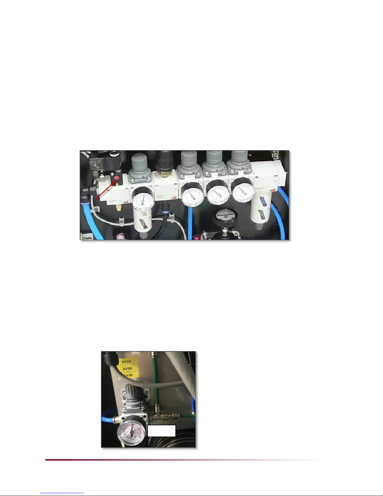
Foil System ECU
1. On the non-operator side of the Foil System on the ECU, using a hex key, open the 4 screws.
2. Verify the following settings:
Main air pressure regulator: 6 bars.
6 bars

Chapter 3 –Operator Maintenance Procedure Details 5 of 22
REG31—Outfeed air jet: 2–4 bars
REG12—Infeed twitch bar (unwind): 1.2–2 bars
REG13—Outfeed twitch bar (rewind): 1.8 bars
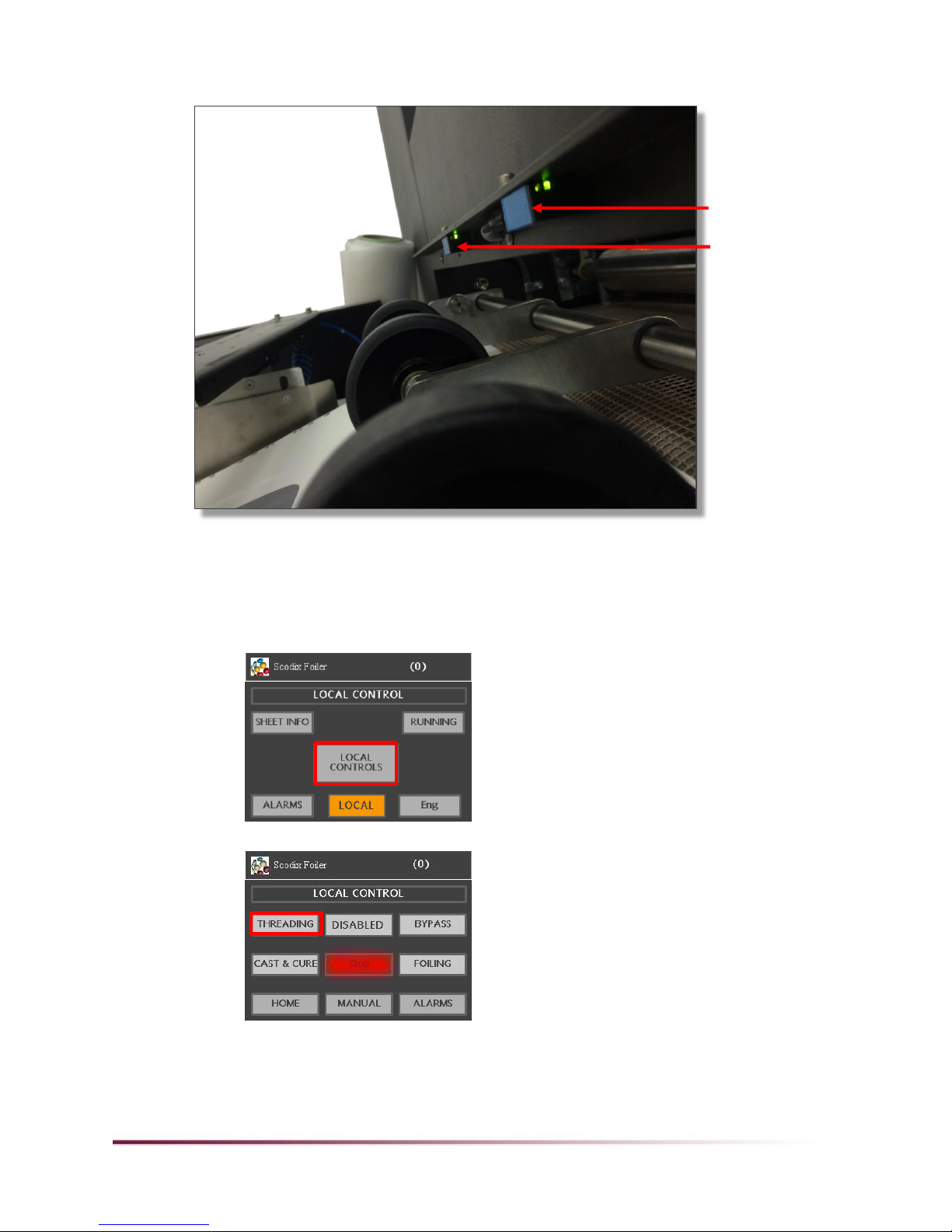
Cleaning the Foil Infeed/Outfeed Conveyor Sensor
Reflectors
Every day, clean the Foil infeed/outfeed conveyor sensor reflectors with a clean, dry cloth, as
described following.
REG31
2–4 bars
REG12
1.2–2 bars
REG13
1.8 bars
Infeed conveyor
sensor reflectors
Infeed conveyor
sensor reflectors
6 of 22 Chapter 3 –Operator Maintenance Procedure Details
1. Using a dry, lint-free cloth, wipe the infeed/outfeed conveyor sensors in one direction.
2. Using a clean section of the cloth, repeat step 1.
3. To enable access to the infeed reflectors, move the stitch area of the infeed conveyor directly
under the sensors:
a. In the HMI main menu, go to LOCAL > LOCAL CONTROLS.
b. Press THREADING.
Outfeed conveyor
sensor reflectors
Chapter 3 –Operator Maintenance Procedure Details 7 of 22
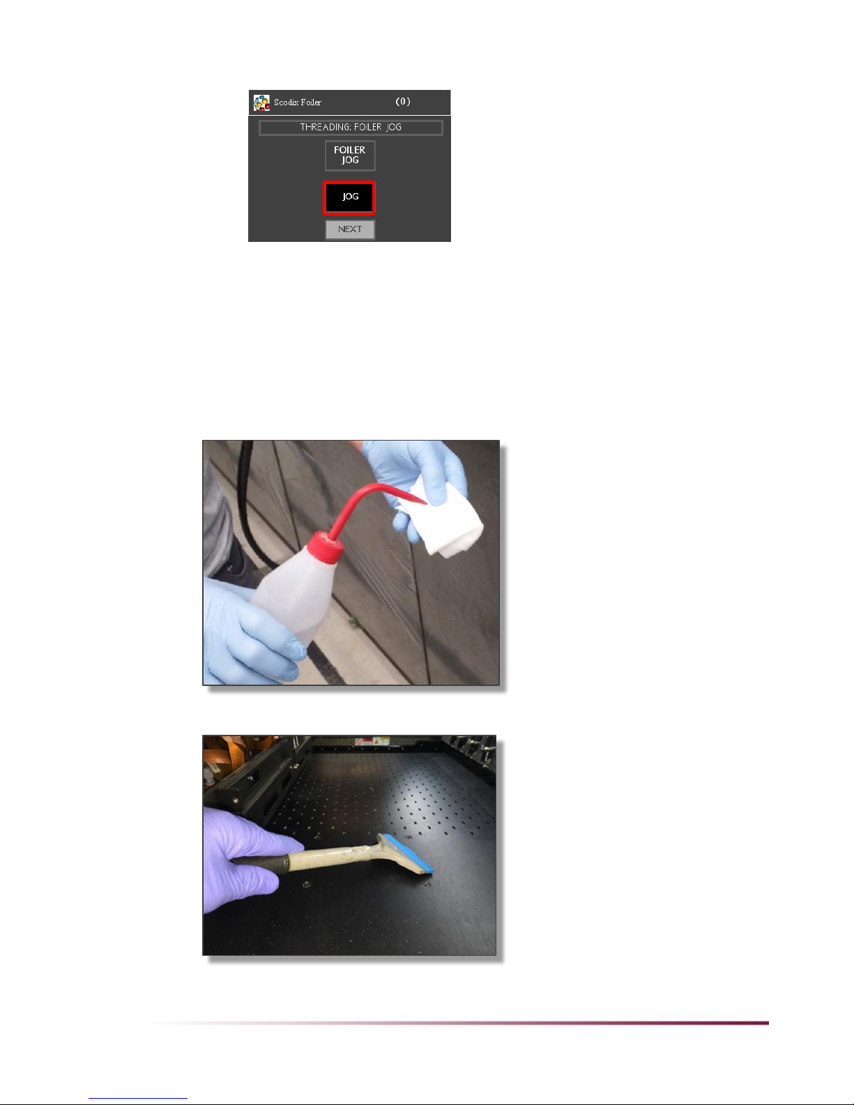
c. Press NEXT twice (or until JOG appears).
d. Press JOG until the stitch is directly under the sensors.
4. Using a dry, lint-free cloth, wipe the infeed reflectors in one direction.
5. Using a clean section of the cloth, repeat step 4.
6. Repeat steps 3–5 for the outfeed reflectors.
Cleaning the Press Print Tables
Every day, wearing gloves, fold and wet a lint-free wipe with isopropyl alcohol (IPA) and clean the
polymer from the printing tables.
To remove cured polymer, use a plastic scraper.
8 of 22 Chapter 3 –Operator Maintenance Procedure Details
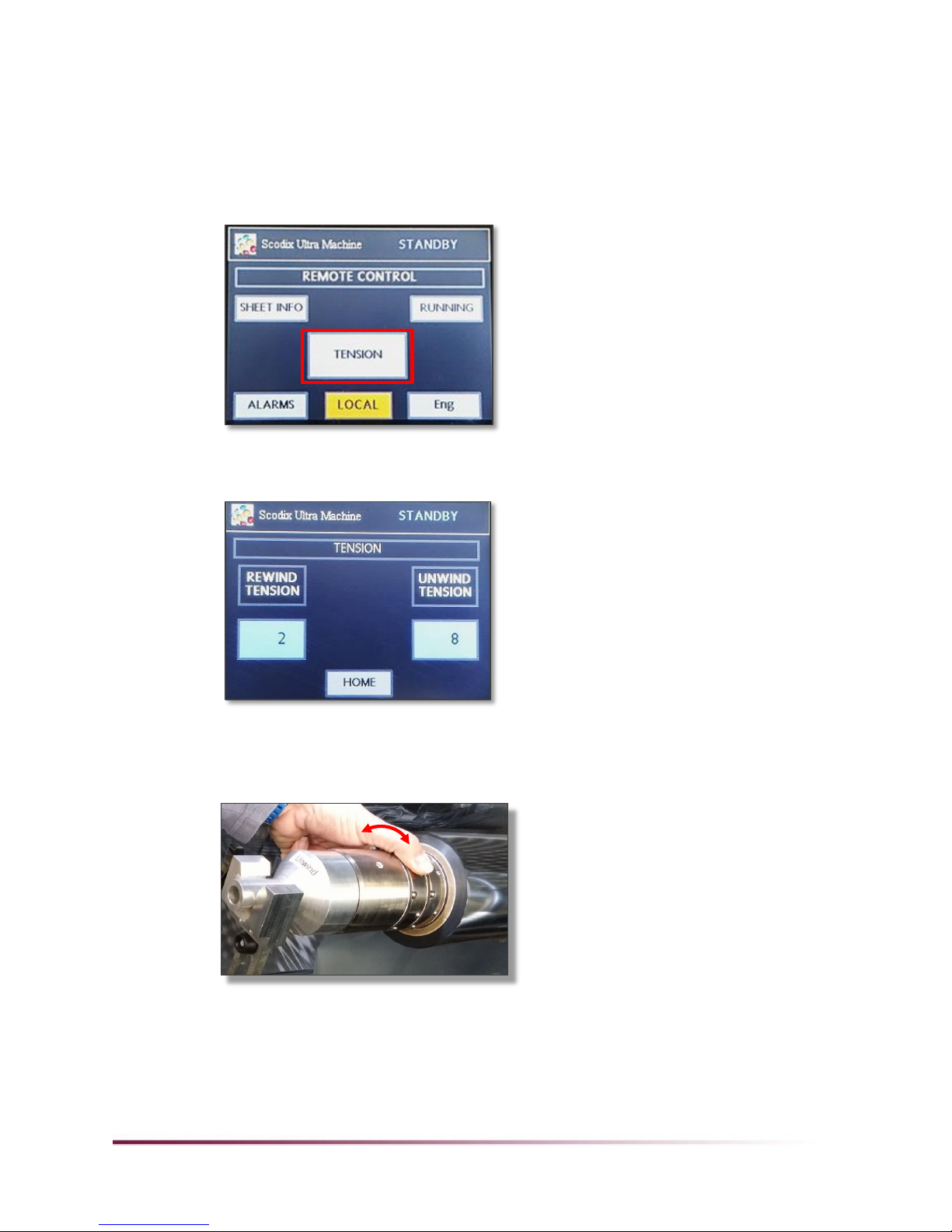
Checking the Foil Rewind and Unwind Shaft Tension
Once a week, check the Foil rewind and unwind shafts for the correct expanding operation (tension),
as follows:
1. Open the Foil System's cover.
2. On the operator station, in REMOTE CONTROL mode, press TENSION.
3. Record the current tension values to use as a reference. You may need to obtain these values
again after the test.
4. Test the tension:
Set the tension to 0. Verify that you can easily rotate the differential shaft ring.
Set the tension to 100. Verify that you cannot manually rotate the differential shaft ring.
If the differential shaft ring did not react as specified in step 4, call your service representative.
Chapter 3 –Operator Maintenance Procedure Details 9 of 22
General Dusting
Once a week, wipe the dust from the press.
1. Verify that the machine is turned off.
2. Open the covers of each unit - the Feeder, Engine, UV Conveyor, Stacker, and Foil System if
relevant, and remove any dust and dirt from machine surfaces with a clean, lint-free cloth, or with
air pressure.
3. Clean internal paper-path components.
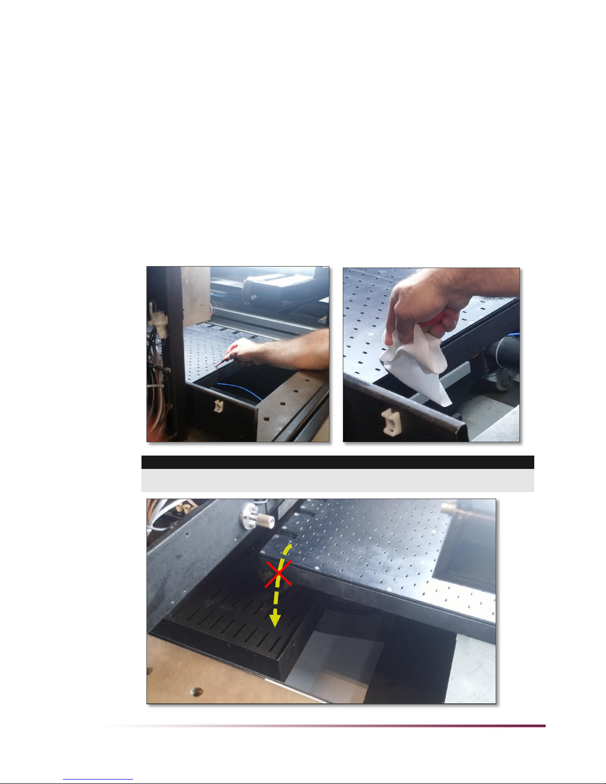
Cleaning the Print Table Vacuum Holes
Once a week, clean the print table vacuum holes.
1. Press an emergency button.
2. Move the table towards the feeder side to clear the area under the UV LED module.
3. Clean the print table vacuum holes with a 2.5 mm Allen key and clean room wipes.
CAUTION!
Do not allow dirt particles to fall into the waste bath! Particles in the waste bath can block the polymer
passageways. Wipe dirt away from the waste bath.

10 of 22 Chapter 3 –Operator Maintenance Procedure Details
Cleaning the UV LED Bridge
Once a week, using a lint-free cloth dampened with isopropyl alcohol (IPA), clean the light source
emitting windows of the UV LED.
1. Turn off CB #23 to disconnect DC power from the UV LED.
1. Press an emergency button.
2. Move the table towards the feeder side to clear the area under the UV LED module.
3. Visually inspect the bridge by using a phone to photograph in the position shown following.
Important:
The phone must not touch the LED.
4. If necessary, clean the bridge (make sure to wear gloves) as follows:
Uncured polymer: Wipe the bridge with a lint-free cloth dampened with IPA.
Dirt
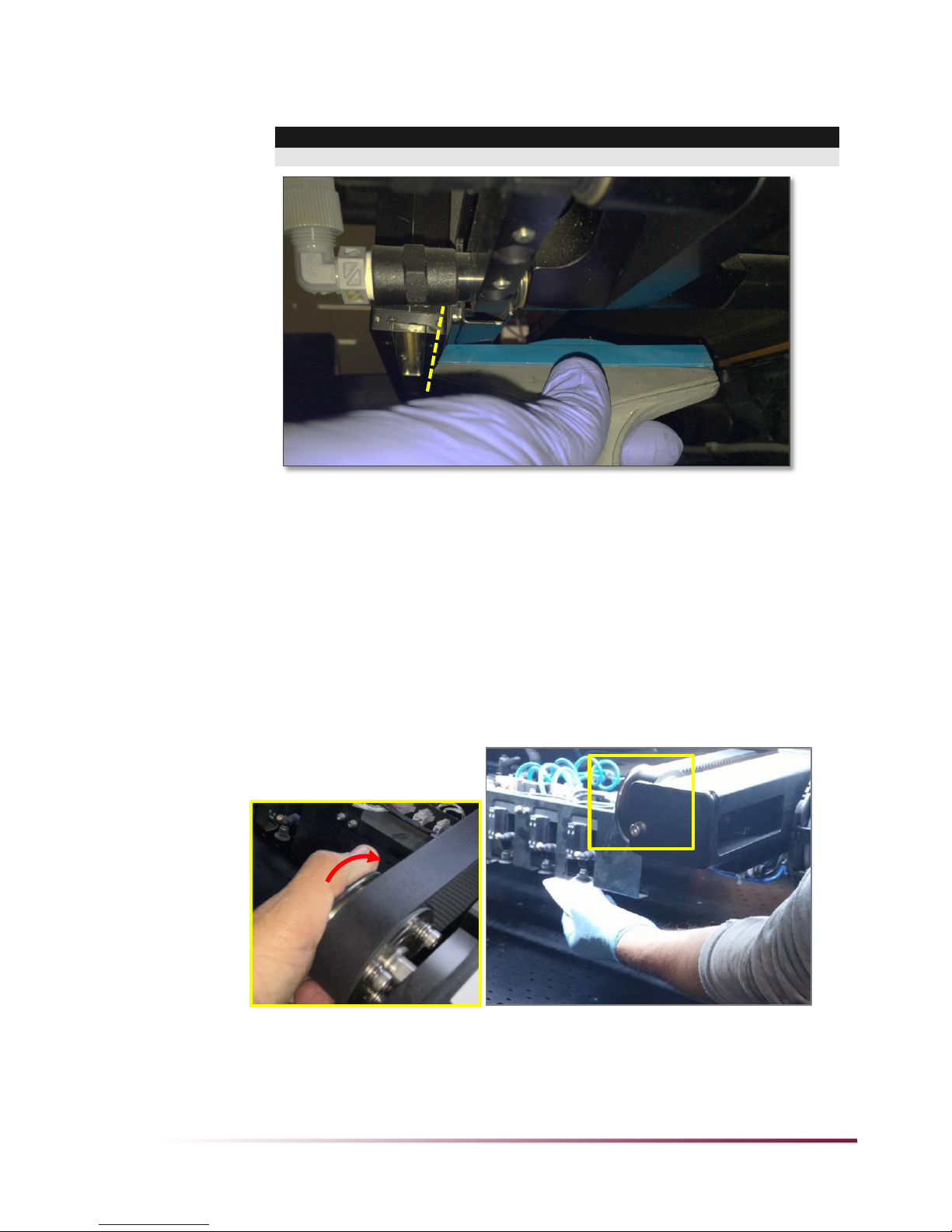
Chapter 3 –Operator Maintenance Procedure Details 11 of 22
Cured polymer: If there is cured polymer on the bridge, remove it very carefully using a
plastic scraper.
Important!
Do not scrape the glass! Scrape only on the bridge, as shown.
5. If the glass is also dirty, wipe with a lint-free cloth and IPA.
Cleaning the Suction Cups of the Loader and the Print
Head Cleaning Unit
Once a week, using ethanol or IPA, clean the Suction Cups of the Loader System and the Print Head
Cleaning Unit.
Loader:
1. Open the operator-side door.
2. To access the Suction Cups, rotate the pulley clockwise, as shown.
3. Using ethanol or IPA and lint-free wipes, wipe the entire surface of the Suction Cups.
12 of 22 Chapter 3 –Operator Maintenance Procedure Details
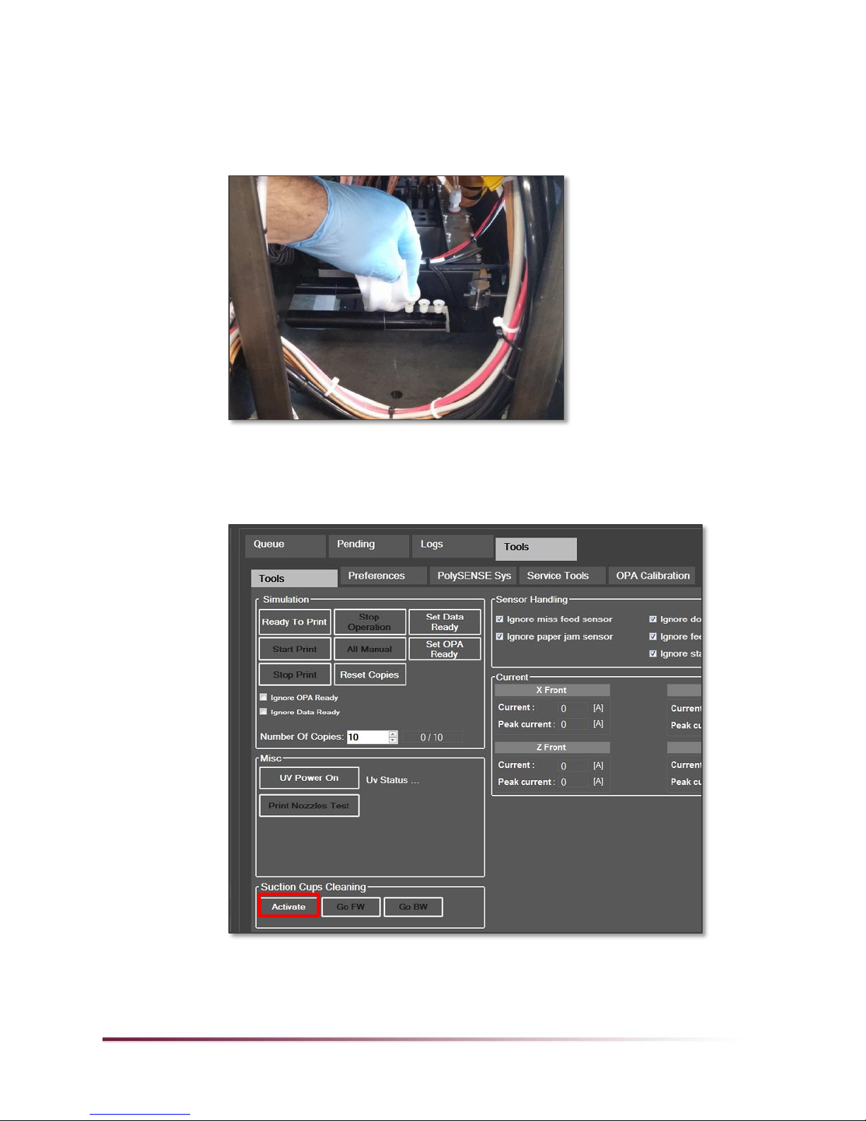
Cleaning Unit:
1. Clean the 3 external Suction Cups:
a. Open the operator-side door.
b. Using ethanol or IPA and lint-free wipes, wipe the entire surface of the 3 Suction Cups that are
closest to you.
c. Close the operator-side door.
2. Clean the 3 internal Suction Cups:
a. Lower the table: In the Scodix software, in Ready mode, go to Tools > Tools > Suction Cups
Cleaning and click Activate.
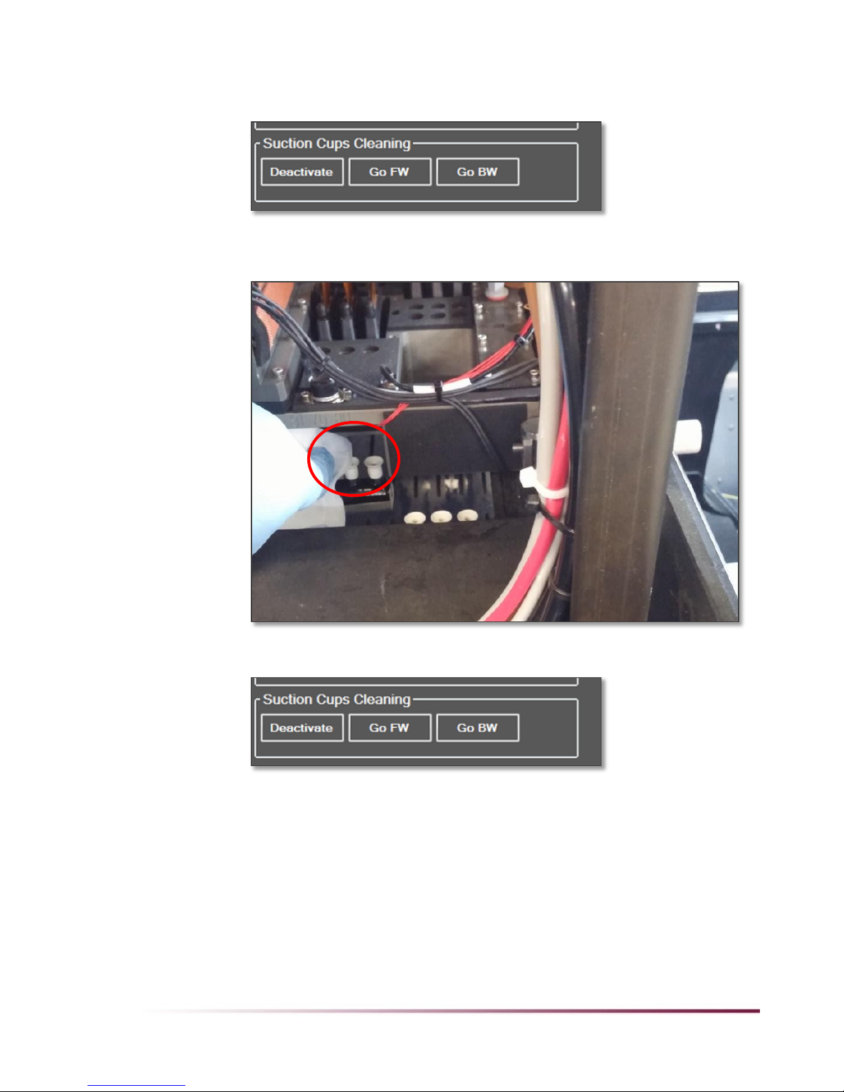
Chapter 3 –Operator Maintenance Procedure Details 13 of 22
b. With Activate enabled (button changes to Deactivate), press and hold the Go FW button so
that the Suction Cups descend as far as possible, and when they start moving away, release
the button.
c. Open the operator-side door.
d. Using ethanol or IPA and lint-free wipes, wipe the entire surface of the 3 Suction Cups that are
farther from you.
e. Close the operator-side door.
f. Press Deactivate.

14 of 22 Chapter 3 –Operator Maintenance Procedure Details
Cleaning Foil Station Rollers and Heater Cover
Once a month, clean the Foil Station rollers:
1. Remove the foil rolls from the rewind and unwind differential shafts.
2. Using a dried clean-room wipe (or if necessary, using IPA), wipe clean the metal twitch rollers
(1,2), the pull roller (5), the idler roller (3), the rewind and unwind shafts (6, 7) and the heater
cover (4).
1
1
2
4
1
3
1
5
1
6
7
Chapter 3 –Operator Maintenance Procedure Details 15 of 22
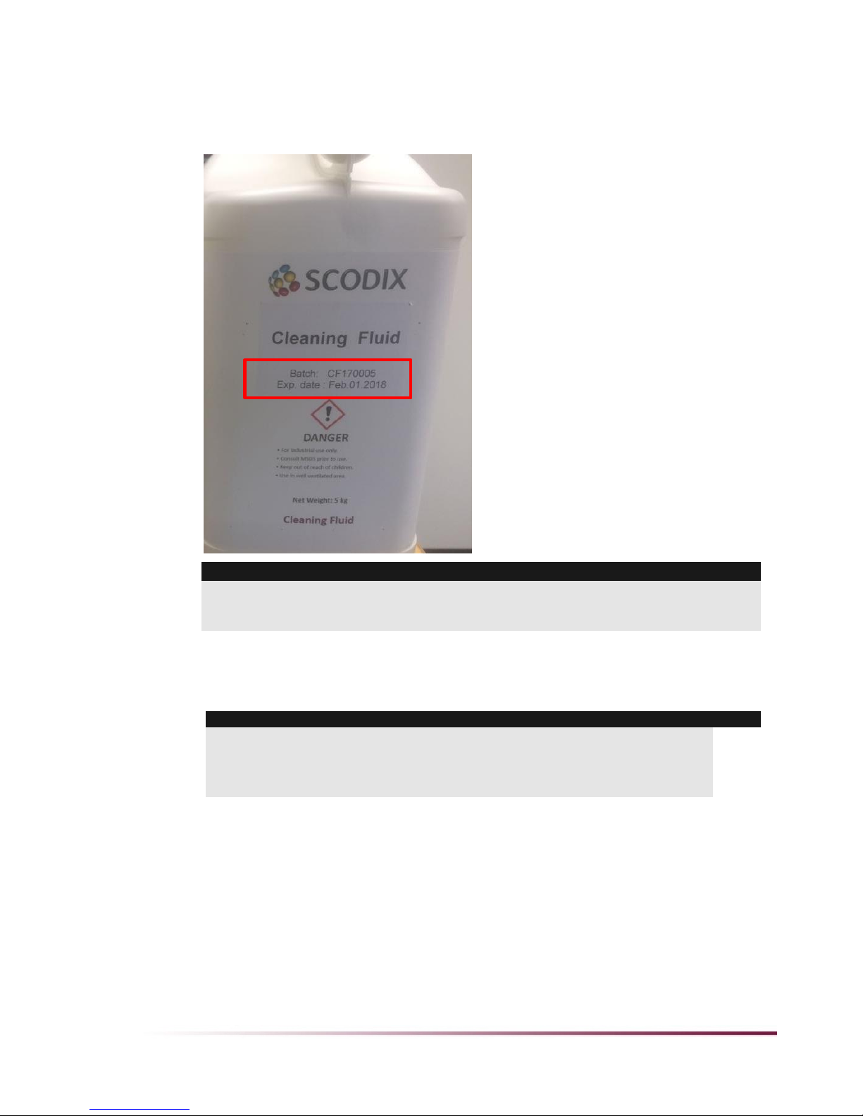
Checking the Polymer Expiration Date
Once a month, check the expiration date on all polymers and cleaning (or flushing) fluids in use and in
stock, and verify that none have expired.
CAUTION:
Do not use expired polymer. Using expired polymers and cleaning (or flushing) fluids can lead to
blocked print heads and material build-up inside the polymer system that standard cleaning and
flushing cannot repair.
Checking Tracking and Condition of Conveyor Belts
Once a month, check the condition of the Engine unit and Foil System UV conveyor belts.
Notes:
In the Foil System, to avoid wasting foil, first remove the roll of foil from the rewind shaft.
Then, using the HMI JOG procedure, move the belt, as described in step 3 on page 6.
In the Engine unit, if the stitch section of the belt is not visible, run print jobs one at a time
until the stitch area is visible.

16 of 22 Chapter 3 –Operator Maintenance Procedure Details
Verify the following:
The belts show no wear and tear.
The belts are centered and stable.
The Engine belt stitch area is smooth.
The Engine belt covers the external line of vacuum holes (see following illustration) on each side.
The Foil Station infeed sensors' red lights are centered in the conveyor belt cut-outs.
If the conveyor belts' condition is not as required, call your service representative.
Cleaning the OPA Bridge Encoders and Camera
Encoders
Once every three months, using a lint-free cloth, clean the OPA bridge encoders, camera encoders, and
camera lenses.
Important:
To prevent damaging the cameras during cleaning, perform this procedure first thing in the morning
after startup, when the cameras' position does not interfere with accessing the center of the machine.
Example of bad
position:
Vacuum holes
are not covered
Table of contents
Popular Power Tools manuals by other brands


Draper
Draper D20 user manual

aquatechnik
aquatechnik BST 32 PLUS Instructions for use

Big Daishowa
Big Daishowa BBT40-AG90-CA4SGM-226 Operation manual

Dynabrade
Dynabrade Dynangle II 14300 Important operating, maintenance and safety instructions

EINHELL
EINHELL TC-JS 18/2700 Li Original operating instructions

Baileigh
Baileigh SS-2822 Operator's manual