Scolmore ESP beacon BA4ZM User manual

Assist Call BA4ZM
Four Zone Controller
Installation and Operation Manual

Page 2 of 8
Table of Contents
1Introduction..........................................................................................................................3
1.1 What is an Emergency Assistance Alarm ? ........................................................................3
1.2 Suitability ......................................................................................................................3
2Product Overview ..................................................................................................................3
3Design Guidelines..................................................................................................................3
3.1 Ceiling Pull Cord location ................................................................................................3
3.2 Overdoor Indicator location.............................................................................................3
3.3 Cancel/reset point location..............................................................................................3
4Important Safety Information .................................................................................................4
4.1 Unpacking the BA4ZM .................................................................................................5
5Installation ...........................................................................................................................5
5.1 Connecting the BA4ZM Four Zone Controller .................................................................5
5.2 Schematic Example ........................................................................................................6
5.3 Additional Functions .......................................................................................................6
5.3.1 Buzzer Volume Control ...........................................................................................6
5.3.2 Fault Monitored Zones ............................................................................................6
5.3.3 Volt Free Relay ......................................................................................................6
5.3.4 Lamp + Buzzer Test ...............................................................................................7
5.4 System Operation ..........................................................................................................7
5.4.1 Raising the Alarm inside the WC..............................................................................7
5.4.2 Indication outside the WC.......................................................................................7
5.4.3 Acknowledging the alarm........................................................................................7
5.4.4 Resetting the system..............................................................................................7
6Maintenance .........................................................................................................................7
7Optional Equipment ...............................................................................................................7
Notes............................................................................................................................................7

Page 3 of 8
1Introduction
1.1 What is an Emergency Assistance Alarm ?
An emergency assistance alarm is used by disabled people to summon assistance.
The system generally consists of a ceiling mounted pull cord, a cancel plate, and an over door indicator
plate. These are connected back to an Assist Call controller or Beacon master station depending on
the chosen configuration.
1.2 Suitability
An Emergency assistance alarm must be provided to all accessible toilets, accessible bathrooms,
accessible bedrooms, accessible showers and accessible changing areas.
The Assist Call system is designed to fully comply with BS8300- 2018, emergency assistance alarms are
called for in all new buildings other than dwellings in the following “Building Regulations Approved
Document M:2020”.
2Product Overview
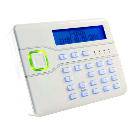
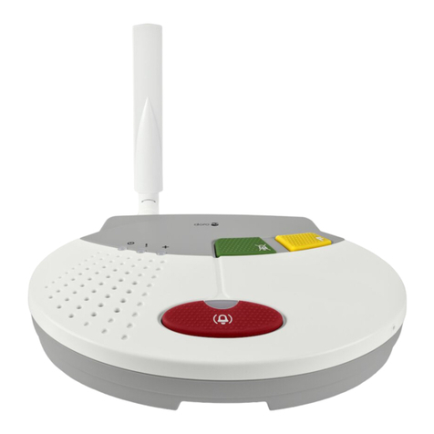
The Assist Call emergency assistance alarm is a 2 wire system consisting of a 4 Zone controller with
separate power supply which should be located in a permanently staffed area, ceiling pull cord located
near to the WC, cancel plate also located near to the WC and over door indicator plate located above
the door outside of the WC.
Additional assist call devices can be connected to the circuit of either one additional cancel plate or over
door indicator and up to 5 additional ceiling pull cords. Assist call devices can be wired in any order so
wiring runs can be kept to a minimum.
The Assist Call system wired from a 4 zone controller features BS8300 “acknowledge” function, this
requires that ”visual and audible feedback should beprovided to indicate that, when the alarm has been
operated, the emergency assistance call has been acknowledged and is being actioned.
Note
an
indication that assistance is on its way will reassure those in distress.”
All Assist Call devices utilise blue halo indication so that they will not confused with fire alarm devices.
3Design Guidelines
Before designing an emergency assistance alarm the guidelines in BS8300:2009 and “Building
Regulations Approved document M :2020” should be consulted first.
3.1 Ceiling Pull Cord location
The ceiling pull cord should be located ideally within the grab rail such that it is reachable from the WC
and from the floor close to the WC
Ceiling pull cords should consist of 2 red bangles of 50mm diameter one set at a height of between
800mm and 1000mm and the other set at a height 100mm above the floor.
3.2 Over door Indicator location
The over door indicator should located so that it is easily seen and heard by those able to give
assistance.
3.3 Cancel/reset point location
The cancel point should be located such that it is reachable from the wheelchair, WC, tip up seat in a
shower facility or bed within an accessible bedroom. The cancel point bottom edge should be between
800mm and 1000mm above the floor.
Please see illustration on next page for more information on locations, heights etc.

Page 4 of 8
4Important Safety Information
This Equipment must only be installed and maintained by a suitably skilled and competent person.
This Equipment is defined as Class 2 in EN60950 (Low Voltage Directive) and must be EARTHED.
The BA4ZMPS requires a 3A switched fuse spur.
*Do not connect 230vAC to the BA4ZMPS Controller*
Caution
Indoor Use Only
Warning Shock Hazard-
Isolate Before Opening
Warning
TO REDUCE THE RISK OF FIRE OR ELECTRIC
SHOCK, DO NOT EXPOSE THIS UNIT TO RAIN
OR MOISTURE
Warning
THIS UNIT MUST BE EARTHED
Warning
NO USER SERVICEABLE PARTS

Page 5 of 8
Anti-static handling guidelines
Make sure that electrostatic handling precautions are taken immediately before handling PCBs and other
static sensitive components.
Before handling any static-sensitive items, operators should get rid of any electrostatic charge by
touching a sound safety earth. Always handle PCBs by their sides and avoid touching any components.
4.1 Unpacking the BA4ZM
Remove the equipment from its packing, and check the contents against the following list:
•BA4ZM - Four zone controller, c/w 6 no 2 way fitted connectors.-
•Instruction Sticker (to be located near the controller).
•Installation and operation manual.
•Accessory pack with the following contents:-
o2no device mounting screws.
o4 no EOL 10K resistors.
5Installation
5.1 Connecting the BA4ZM Four Zone Controller
The BA4ZM controller mounts ono a 25mm UK double gang back box, it requires power from a
12volt regulated power supply unit such as the BA4ZMPS
The terminals on the BA4ZMPS are marked “12V out” 0 & +V, which should be connected to the
terminals marked power 0 & + on the BA4ZM

Page 6 of 8
Optional Battery Back Up
If battery backup is required use BA4ZMPSBB battery pack, this requires an additional double socket
box which should be mounted directly underneath the BA4ZMPS. The battery is complete with pre
terminated battery wires which connect to the BA4ZMPS via a JST connector marked battery.
The field devices are wired to the four terminals marked Zones 1 to 4, 0 and +, the devices are polarity
sensitive, cabling between the controller and the devices is 2 core 1 mm CSA flex, wired in a radial
circuit.
Note: The BA4ZM is only compatible with Beacon Assist Call devices.
All system wiring should be installed to meet the appropriate parts of BS 7671 (Wiring Regulations).
Other national standards of installation should be adhered to where applicable.
Extra Low Voltage (ELV) Wiring:- Always segregate low voltage wiring from the main wiring
5.2 Schematic Example
Note: The plates can be wired in any order to suit the installation.
5.3 Additional Functions
5.3.1 Buzzer Volume Control
There is a potentiometer on the rear of the PCB labelled Sounder volume turning it anti clockwise
reduces the volume.
5.3.2 Fault Monitored Zones
The line circuits are monitored for open and short circuit and require the supplied EOL 10K resistor to
be fitted in the last assist call device in the circuit. Faults are indicated by the zone indicator flashing
yellow and the buzzer sounding. By pressing the accept button the fault buzzer will be muted and the
fault indicator will go steady.
5.3.3 Volt Free Relay
The controller has an on board volt free relay C, No contact rated at 1A @30vdc. The relay operates
whenever a call is present. This can be used to signal ancillary equipment such as sounders or beacons.
An external power supply would be required for this purpose.

Page 7 of 8
5.3.4 Lamp + Buzzer Test
When the accept button is pressed for 5seconds a lamp and buzzer test will be performed, the test is
cancelled by pressing the button again.
5.4 System Operation
5.4.1 Raising the Alarm inside the WC
The person in distress raises the alarm by pulling on one of the red pull cord bangles, the blue indicator
on the ceiling plate will indicate steady blue and the blue indicator flash and sounder will activate on the
cancel plate.
5.4.2 Indication outside the WC
The over door indicator plate will flash and sounder will activate to show the location of the alarm, the
ViAC-4ZC controller should be located within a permanently staffed area. The blue zone indicator will
flash and the sounder will activate on the controller to alert staff of an alarm.
5.4.3 Acknowledging the alarm
A member of staff acknowledges the alarm bypressing the Accept button on the controller, the blue
zone indicator will change state from flashing to steady and the internal sounder will sound
intermittently every 15 seconds. The ceiling pull cord indication will extinguish, the blue indicator on the
cancel plate and the over door indicator changes state from flashing to steady with intermittent sounder
operation every 15 seconds to confirm to the occupant that help is on the way.
5.4.4 Resetting the system
When the call has been attended to, the alarm is reset by pressing the cancel button within the WC. All
indicators will extinguish and buzzers will cease.
6Maintenance
Assist Call emergency assistance alarms should be tested as follows:
Frequency
Test
Monthly
Test the system monthly by operating a pull cord, acknowledge the call using the
controller, check all indicators and reset from the cancel plate within the WC. Record
these results in the site log.
7Optional Equipment
Battery backup is available as an additional piece of equipment, it consists of a Yuasa 12v 0.8AH VRSLA
battery and stainless steel cover plate. It mounts onto a double socket box (Not Supplied)
This will provide 1 x BA4ZM with standby of 12 hours i 2 x BA4ZM are connected then standby will be 6 Hrs.
Notes

Page 8 of 8
For more product information please visit www.espuk.com
E&OE - Errors and omissions excepted.K21
Elite Security Products UK, Unit 7 Target Park, Shawbank Road, Lakeside, Redditch, Worcestershire, B98 8YN
Registered in England Number Company Registration No: 02769392, VAT Registration GB614686525
Table of contents
