MAKS Siren User manual

ISM wireless interface, up to 2000 m 868.0... 868.6 MHz
secure two-way communication
key - 256 bits
Power
(lithium batteries included)
two CR123A, 3V batteries
consumption in standby mode
no more than 5 µA
alarm consumption
no more than 70 µA
For more information on setting up and operating the
device, please visit www.maks.systems
This wireless siren is designed for alarm notification when the wireless
detectors of MAKS PRO security center are triggered.
It is installed indoors to warn about the danger or scare off intruders.
The device has contacts for connecting the arming information LED and
external reed switch.
Radio communication
The siren transceiver operates in several channels of 868.0 ... 868.6 MHz
band for redundancy
Secure two-way radio communication.
Distance - up to 2000 m in the open space.
Three gradations of power, the maximum - up to 20 mW.
WIRELESS SIREN
• miniature siren for indoor use
• elegant design
• available in two colors
• sound pressure level - 85 dB at a distance of 1 m
• arming confirmation indicator connection
• 868,0 ... 868.6MHz, several channels for
redundancy, range up to 2000 m
• power supply - two CR123A batteries
• up to five years of service
• easy and fast installation
Characteristics
Setting up
The siren operates only with the MAKS PRO wireless security system center,
connection to other systems is not provided.
The siren is connected to the security center and configured using the
MAKS Setup mobile application. The volume and running time of the
audible alarm are adjustable.
Case color
white, black
84.5 x 84.5 x 24.3 mm
Weight
no more than 1.5 m
Operating temperature range
from -10°C to +55°C
Dimensions
service life of battery
up to 5 years
radio consumption
no more than 35 µA
distance (cable length) to external
elements
не більше 1,5 м
Connection to MAKS Siren
external LED and reed switch
Sound pressure level at 1 m
at least 85 dB
3
Light indication, adjustable
built-in or external
indicator
Volume levels, adjustable
Features
The time for switching on the built-in indicator or external arming informa-
tion LED is 15 seconds.
For "Armed" status indication, you can set the built-in indicator or external
LED to flash once every 10 seconds.
If MAKS PRO is in the "Armed (Stay)" mode, the alarm sound will always be
activated at the minimum volume.
In the event of an alarm, the MAKS wireless siren will be activated no later
than in 10 seconds (communication period with the security center).
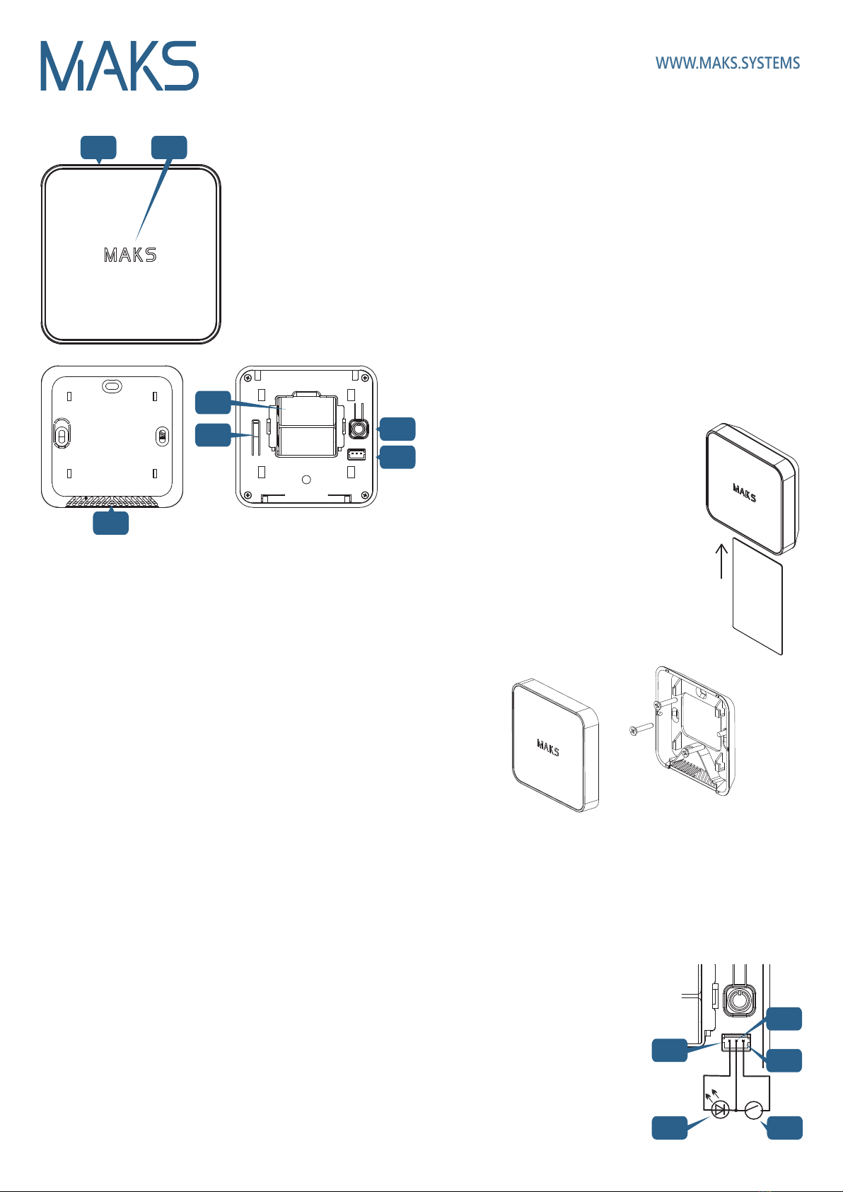
Functional parts of the device
WWW.MAKS.SYSTEMS
1. Siren case
2. Light indicator
3. Resonator openings
4. Batteries
5. Tamper
6. On/off button
7. Connector for reed switch
and LED
Selecting the installation location
Carefully select the installation location of the MAKS Siren.
The device should not be placed:
1. Outdoors or in areas with unacceptable humidity and temperature
2. In places with a high level of radio interference
3. Near objects that can cause radio signal attenuation or shielding (metal,
mirrors, etc.)
4. At a distance of less than 1 m from the security center
Installation and connection
1. Use a plastic card to remove the device from
the plate
2. Insert the card into the slot
3. Press the fixation elements down with the card
4. Move the siren upwards
5. Remove the MAKS Siren from the mount
6. Fit the mount using the screws
and wall plugs provided.
7. Place the siren on the bracket and slide it down
to fix the bottom and top parts and lock the tamper
contact 5. Flashes on indicator 2will confirm
that the tamper is locked in place.
Registration and setup
1. Place the siren at a distance of no more than 2 m from the MAKS
PRO security center. Registration is run at a minimal possible power to
avoid the influence of neighboring systems that can be being configured
nearby.
2. Start the MAKS SETUP application
3. Follow the application instructions to connect to the MAKS Siren and
start the registration of MAKS wireless devices
4. Turn on the MAKS PIR, after 10-20 seconds it will be registered
5. Set up a new device in your mobile application
Switching on and off
Press button 6to switch on the device - the indicator will be on and you
will hear a sound signal.
To turn off the device, press and hold button 6for 3 seconds, until the light
indication goes out.
Before installing the MAKS Siren, register it in the MAKS PRO and test the
siren signal level using the MAKS Setup app.
We recommend to install the device in the following order:
1. Selecting the installation location with the best signal
2. Mounting the rear plate (mount)
3. Siren installation
Device installation
Battery replacement
1. Use a plastic card to remove the device from the mount
2. Pull out and replace the batteries
3. Place the siren on the bracket and slide it down until it locks
Indication
Sleep mode - indicator off
Alarm mode - light indicator flashes red, the alarm sounds
Arming mode confirmation - short beep. Turn on the external LED or the
built-in indicator for 15 seconds (if configured)
Arming mode - flashing of the external LED or built-in indicator every 10
seconds (if configured)
Disarming confirmation - two short beeps
1
3
6
5
7
Connecting the reed switch
and LED
Connect the reed switch and LED
to the connector terminals
as shown.
9. LD contact (+ LED)
10. GND contact (earth)
11. DC contact (reed switch)
12. LED (LED)
13. Reed switch
911
12 13
10
4
Display in communication test mode
2
Excellent connection - LED indicator flashes green
Satisfactory connection - LED indicator flashes yellow
Poor connection - LED indicator flashes red
No connection L- ED indicator flashes red quickly
In test mode, the unit's radio transmitter operates at medium power.
Other MAKS Security System manuals


Popular Security System manuals by other brands

Transistor
Transistor Lynx Tactum manual

Simplex
Simplex 4010ES installation instructions

Visonic
Visonic POWERMAXCOMPLETE PANEL - Installer's guide

Carlos Silva
Carlos Silva SAR plusCOM installation guide

Pyronix
Pyronix Paragon Plus User instructions

aquilar
aquilar DOLEJSZ AquiTron AT-RAP-12 Installation & operation instructions


 user guide")
