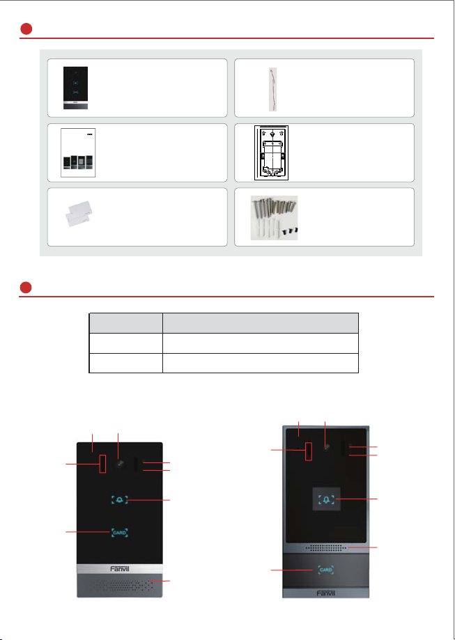
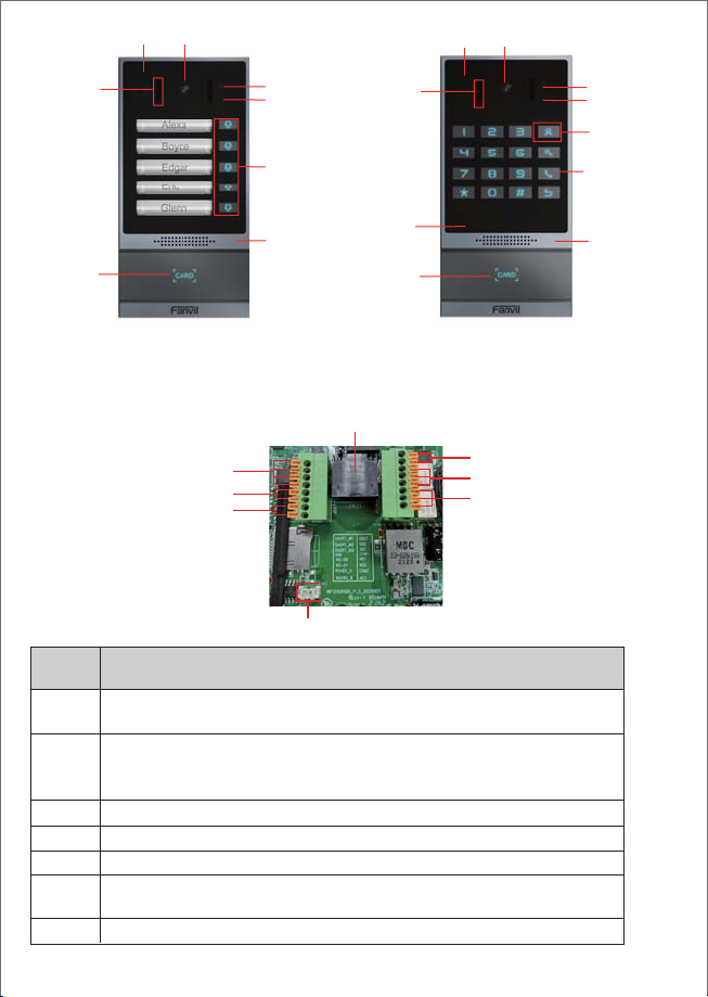
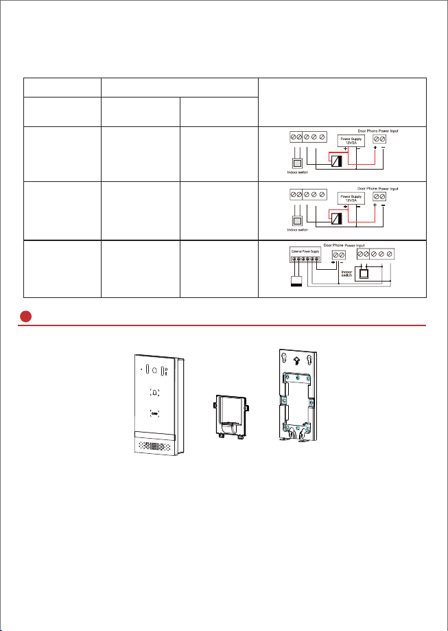
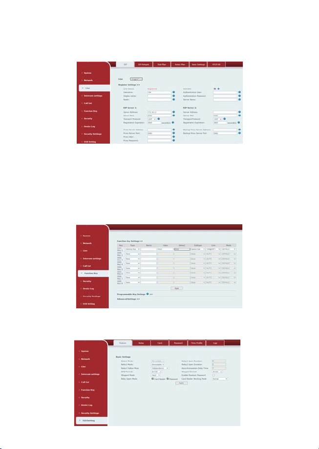
Fanvil i61 User manual

Quick Installation Guide
i61&i62&i63&i64
www.fanvil.com

1) Panel
Model
Package Contents
Physical specification
Video Door Phone
Quick Installation Guide
Connector
Mounting Template
Device sizeevice
i61 159.7 x 88 x 36.15 (mm)
i62&i63&i64 177.4 x 88 x 36.15 (mm)
Photoresistor
TOF sensor
IR LED
DSS Key
RFID Cards 2pcs Screw and tool
MIC Camera
RFID area
15 CM
Wall mounting template
UP
1
2
3
4
5
6
7
8
9
10
11
12
13
14
0
Hole 1 Hole 1
Hole 2 Hole 2
Hole3
Hole 1 Hole 1
Hole 1.Custom wall hanging
Hole2.86 Box
Hole3.Gang- BOX
Hole 3 Hole3
Hole3
Hole 3 Hole3
12345678 CM
0
MIC Camera
Photoresistor
TOF sensor
IR LED
DSS Key
RFID area
Speaker
Speaker
i62i61
Quick Installation Guide
i61&i62&i63&i64

1
2
3
4
5
8
Ethernet interface: standard RJ45 interface, 10/100M adaptive,
it is recommended to use five or five types of network cable
Description
Serial
number
Two sets of short-circuit input detection interfaces: for connecting
switches, infrared probes, door magnets, vibration sensors and
other input devices
Wiegand interface
RS485 interface
Power interface: 12V/1A input up positive, down grounded
Two sets of short-circuit output control interface:
used to control electric locks, alarms, etc.
Line out interface
6、7
2) Interface description
Open the rear case of the device, there is a row of terminal blocks for connecting
the power supply, electric lock control, etc. The connection is as follows:
MIC Camera MIC Camera
IR LED
IR LED
Dialing key
RFID area
LED
RFID area
Photoresistor
TOF sensor
Speaker
DSS Key
DSS Key
Photoresistor
TOF sensor
Speaker
ʒ
ʓ
ʕ
ʖ
ʗ
ʘ
ʙ
ʔ
i64i63

3) Wiring instructions:
NO:Normally Open Contact;
COM: Common Contact;
NC:Normally Close Contact.
Figure 3-1 Three Major Parts of i61
Wall mounting
Step 1: Installation preparation
A. Check the following contents:
.0VFUHZV[
7$PPVFUHZV[
ijPPVFUHZDQFKRUV[
30PPVFUHZ[
70VFUHZ[
B. Tools that may be required:
Phillips screwdriver,hammer, RJ45 crimper
Electric impact drill with an 8mm drill bit
Figure 3-1
Driving Mode Electric-lock Mode
Passive No electricity
when open
Electrify
when open
ɭ
ɭ
ɭ
ɭ
ɭ
ɭ
Connections
Installation Diagram
Panel Main Body Back Shell Wall Bracket
S-I S-O
Electric lock (normally open type)
No electricity when open the door
NC COM NO
Electric lock (normally closed type)
when the power to open the door
Electric lock (normally open)
Withourt the power to open the door
S-I S-O NC COM NO
NC COM NO P USH GNB 12V
S-I S-O NC COM NO

Step 2: Drilling
A. Place the mounting template with dimensions on the surface of a wall in a
desired flat position.
B. Use an electric drill to drill the 4 holes marked on the mounting template. It is
recommended to drill about 50mm deep. Remove the template when finishing
drilling.
C. Push or hammer screw anchors into the drilled holes.
Step 3: Removing hanging bracket and back shell
A. Detach the wall bracket downward from the device and loosen the four screws
on the rear cover using a screwdriver, as shown in Figure 3-3-aĂ3-3-b.
Figure 3-2 Wall Mounting / Built-in
Step 4: Install the wall bracket, wiring and casing
A. Align the screw holes of the wall bracket with the holes in the wall and fix them
WRWKHZDOOZLWKWKH7$PPVFUHZVDVVKRZQLQ)LJXUH
B. Pass all the wires through the silicone plug in the middle of the bottom case.
All lines should be reserved for 15~20CM length, as shown in Figure 3-5.
Figure 3-3-a Figure 3-3-b
Figure 3-4 Figure 3-5
Note: The outlet hole of the bottom case faces down.

C. Connect the cables of RJ45, power, and electric-lock to the motherboard socket
as mentioned in connectors description (refer to Section 2).
D. Connect the terminal of the wired cable to the motherboard socket (refer to
Section 2).
E. Test whether there is electricity by doing the following: Press the # button for 3
seconds to get the IP address of intercom by voice.Input access password or press
the indoor switch to check electric-lock installation.
Note: Do not proceed mounting until you have finished the electric checking.
F. Attach the device to the wall bracket in a top-down manner, locking the screws at
the Bottom, as shown in Figure 3-6.
Figure 3-6
Flush mounting
Step 1: Installation preparation
A. Check the following contents:
30PPVFUHZV[
30PPVFUHZV[
ijPPVFUHZVDQFKRUV[
.%PPVFUHZV[
7$PPVFUHZV[
ʒʕʓʔ
'VVKGXGTIK /TYZGRRGZOUT*OGMXGS
Decoration
Panel
Small
Stents Device Wall Box

IP Door Phone Setting
Method 2:
Long press DSS key for 3 seconds(after power-on for 30 seconds), and when the
speaker beeps rapidly, Press the speed-dial button within 5 seconds, and the
system will automatically announce the IP address by voice.
In addition, device provides the device surface DSS key operation to switch IP
address acquisition mode:
Touch and hold the speed-dial button for 3 seconds, wait for the speaker to beep,
press the speed-dial button three times within 5 seconds, and the system will
automatically announce the IP address by voice after successfully switching to the
network mode.
Step 1: Log in the door phone
Input IP address (e.g. http://192.168.1.128) into address bar of PC’s web browser.
The default user name and password are both admin.
Searching Door Phone
Here are two methods as shown below to search the device.
Method 1:
Open the iDoorPhone Network Scanner. Press the Refresh button to search the
device and find the IP address.( Download address:
http://download.fanvil.com/tool/iDoorPhoneNetworkScanner.exe )

Step 2: Add the SIP account.
Set SIP server address, port, user name, password and SIP user with assigned
SIP account parameters.
Select “Activate”, and then click Apply to save this setting.
Step 3: Setting DSS key
Set the DSS key as shown below for a quick start. Click “Apply” to save this setting.
Type: Memory Key.
Number 1: The DSS Key will dial to this Number 1.
Number 2: If Number 1 is unavailable, it will be forwarded to Number 2.
Line: Working line.
Subtype: Speed dial.
Step 4: Door Phone Setting

Remote Password
6WHS6HWDFFHVVFRQWURORQWKHZHESDJHĺ(*66HWWLQJĺ3DVVZRUGĺ$GG
SDVVZRUGUXOHĺ6HOHFW5HPRWH
6WHS(QWHUWKH1DPH3DVVZRUGDQG1XPEHU3UHVV$GGWR3DVVZRUG7DEOH
6WHS7KHRZQHUDQVZHUVWKHDFFHVVFRQWUROFDOODQGSUHVVHV
GHIDXOWSDVVZRUGRUQHZSDVVZRUGWRRSHQWKHGRRUIRUYLVLWRUV
Door Unlocking Setting
RFID Card
6WHS$FFHVVFRQWUROVHWWLQJVRQZHESDJHĺ(*66HWWLQJĺ$GG&DUG5XOH
ĺ6HOHFW7\SH1RUPDOFDUGSURYLGHVGRRURSHQLQJIXQFWLRQ³$GG´FDUGDQG
“Del” card provides add and delete card function, Default “Normal” card)
6WHS(QWHUH\RXUQDPHDQGFDUGQXPEHUMXVWHQWHUWKHILUVWGLJLWVRIWKH
FDUGQXPEHUDQGFOLFNLQJ$GGWRDGGWKHFDUGWRWKHOLVW
6WHS$FFHVVWKHFDUGUHDGLQJDUHDRIWKHGHYLFHWKURXJKWKHFRQILJXUHG,'
card to open the door.

Local Password
6WHS&RQILJXUHDFFHVVRQ:HEĺ(*66HWWLQJĺ3DVVZRUGĺ$GGSDVVZRUG
UXOHĺ6HOHFW
/RFDORQO\WKHLVXSSRUWVORFDOSDVVZRUGDFFHVV
6WHS(QWHUWKH1DPHDQG3DVVZRUG3UHVV$GGWR3DVVZRUG7DEOH
6WHS2ZQHUVDQGYLVLWRUVFDQRSHQWKHGRRUE\HQWHULQJGHIDXOW
SDVVZRUGRUQHZSDVVZRUGE\XVLQJWKHNH\SDG
This manual suits for next models
3
Table of contents
Popular Security System manuals by other brands

American Dynamics
American Dynamics AD2096A Installation and operating instructions

Bosch
Bosch DIP-3040-00N installation manual

Interlogix
Interlogix ZeroWire user manual

Vacron
Vacron VDH-NK360 Hardware manual

Bender
Bender COMTRAXX MK2430 manual

Honeywell
Honeywell ADEMCO VISTA-10P Installation and setup guide