Scooter Fly 50 4t 4v Instruction manual

WORKSHOP MANUAL
677586 EN
Fly 50 4t 4v

WORKSHOP
MANUAL
Fly 50 4t 4v
Thedescriptionsandimagesinthispublicationaregivenforillustrativepurposesonlyandarenotbinding.
While the basic characteristics as described and illustrated in this booklet remain unchanged, Piaggio &
C.S.p.A.reservestheright,atanytimeandwithoutbeingrequiredtoupdatethispublicationbeforehand,
to make any changes to components, parts or accessories, which it considers necessary to improve the
product or which are required for manufacturing or construction reasons.
Not all versions/models shown in this publication are available in all countries. The availability of each
model should be checked at the official PIAGGIO sales network.
© Copyright 2012 - Piaggio & C. S.p.A. All rights reserved. Reproduction of this publication in whole or
in part is prohibited.
Piaggio & C. S.p.A. Viale Rinaldo Piaggio, 25 - 56025 PONTEDERA (PI), Italy
www.piaggio.com

WORKSHOP MANUAL
Fly 50 4t 4v
This manual has been prepared by Piaggio & C. S.p.A, for use in the workshops of authorized Piaggio
dealers and sub-agents. It is assumed that the person utilizing this manual for servicing or repairing
Piaggio vehicles has knowledge of the principles of mechanics and standard procedures required for
general vehicle repair. Any relevant changes concerning the vehicle characteristics or specific repair
operations will be divulged in the form of updates to this manual. Satisfactory repair or service cannot
be achieved without the necessary equipment and tools. Refer to the pages of this manual concerning
specific tools and equipment and the special tools catalogue.
N.B. Provides key information to make the procedure easier to understand and carry out.
CAUTION Refers to specific procedures to carry out for preventing damages to the vehicle.
WARNING Refers to specific procedures to carry out to prevent injuries to the repairer.
Personal safety Failure to completely observe these instructions will result in serious risk of personal
injury.
Safeguarding the environment Sectionsmarked with this symbol indicate the correct use of thevehicle
to prevent damaging the environment.
Vehicle intactness The incomplete or non-observance of these regulations leads to the risk of serious
damage to the vehicle and sometimes even the invalidity of the guarantee.


INDEX OF TOPICS
CHARACTERISTICS CHAR
TOOLING TOOL
MAINTENANCE MAIN
TROUBLESHOOTING TROUBL
ELECTRICAL SYSTEM ELE SYS
ENGINE FROM VEHICLE ENG VE
ENGINE ENG
SUSPENSIONS SUSP
BRAKING SYSTEM BRAK SYS
CHASSIS CHAS
PRE-DELIVERY PRE DE

INDEX OF TOPICS
CHARACTERISTICS CHAR

Rules
This section describes general safety rules for any maintenance operations performed on the vehicle.
Safety rules
- If work can only be done on the vehicle with the engine running, make sure that the premises are well
ventilated, using special extractors if necessary; never let the engine run in an enclosed area. Exhaust
fumes are toxic.
- The battery electrolyte contains sulphuric acid. Protect your eyes, clothes and skin. Sulphuric acid is
highly corrosive; in the event of contact with your eyes or skin, rinse thoroughly with abundant water
and seek immediate medical attention.
- The battery produces hydrogen, a gas that can be highly explosive. Do not smoke and avoid sparks
or flames near the battery, especially when charging it.
- Fuel is highly flammable and it can be explosive given some conditions. Do not smoke in the working
area, and avoid naked flames or sparks.
- Clean the brake pads in a well-ventilated area, directing the jet of compressed air in such a way that
you do not breathe in the dust produced by the wear of the friction material. Even though the latter
contains no asbestos, inhaling dust is harmful.
Maintenance rules
- Use original PIAGGIO spare parts and lubricants recommended by the Manufacturer. Non-original or
non-conforming spares may damage the vehicle.
- Use only the appropriate tools designed for this vehicle.
- Always use new gaskets, sealing rings and split pins upon refitting.
- After removal, clean the components using non-flammable or low flash-point solvents. Lubricate all
the work surfaces, except tapered couplings, before refitting these parts.
- After refitting, make sure that all the components have been installed correctly and work properly.
- Use only equipment with metric sizes for removal, service and reassembly operations. Metric bolts,
nuts and screws are not interchangeable with coupling members using English measurements. Using
unsuitable coupling members and tools may damage the vehicle.
- When carrying out maintenance operations on the vehicle that involve the electrical system, make
sure the electrical connections have been made properly, particularly the ground and battery connec-
tions.
Fly 50 4t 4v Characteristics
CHAR - 7

Vehicle identification
The chassis prefix is stamped on the right strut.
The engine prefix is stamped on the rear wall of
the transmission crankcase.
VEHICLE IDENTIFICATION
Specification Desc./Quantity
Chassis prefix RP8C52
Engine prefix C522M
Dimensions and mass
Characteristics Fly 50 4t 4v
CHAR - 8

WEIGHTS AND DIMENSIONS
Specification Desc./Quantity
Kerb weight 117 kg
Wheelbase 1345 mm
Length 1,870 mm
Width (handlebar) 705 mm
Height (without mirrors) 1150 mm
Engine
ENGINE
Specification Desc./Quantity
Type single-cylinder, four-stroke and four-valve, air-cooled engine
Bore 39 mm
Stroke 41.8 mm
Engine capacity 49.93 cm³
Max. power 3.2 kW at 8250 rpm
MAX. torque 3.8 Nm at 7,750 rpm
Compression ratio 12.0±0.5
Timing system single overhead camshaft, chain-driven, on the left-hand side,
three-arm rocking levers set up with threaded set screw
Engine idle speed 1900 to 2000 rpm
Air filter Sponge, soaked in a mixture (50% SELENIA Air Filter Oil and
50% unleaded petrol).
Starting system electric starter/kick starter
LUBRICATION engine lubrication with lobe pump (in the crankcase), chain-
driven. Mesh pre-filter and centrifugal filter on the crankshaft
Fuel system Gravity feed, with unleaded petrol (with a minimum octane rat-
ing of 95) with carburettor.
Valve clearance (cold engine) intake 0.10 mm
discharge 0.15 mm
CARBURETTOR depression type, KEIHIN NCV ø 20
Cooling forced air circulation
OIL PUMP
Specification Desc./Quantity
Type Trochoidal
Distance between the rotors Admissible limit clearance: 0.15 mm
Axial rotor clearance Limit values admitted: 0.09 mm
Distance between the outer rotor and the pump body Admissible limit clearance: 0.20 mm
Levelness 0.1 mm
OIL FILTER
Specification Desc./Quantity
Type mesh, plastic and centrifugal filter, before the oil pump and co-
axially mounted onto the crankshaft keyed on the right crank
Transmission
TRANSMISSION
Specification Desc./Quantity
Transmission With automatic expandable pulley variator, torque server, V-
belt, automatic clutch, gear reduction unit.
Fly 50 4t 4v Characteristics
CHAR - 9
Capacities
CAPACITY
Specification Desc./Quantity
Fuel tank 7±0.5 lt
Rear hub 85 cm³
Engine oil ~ 850 cc
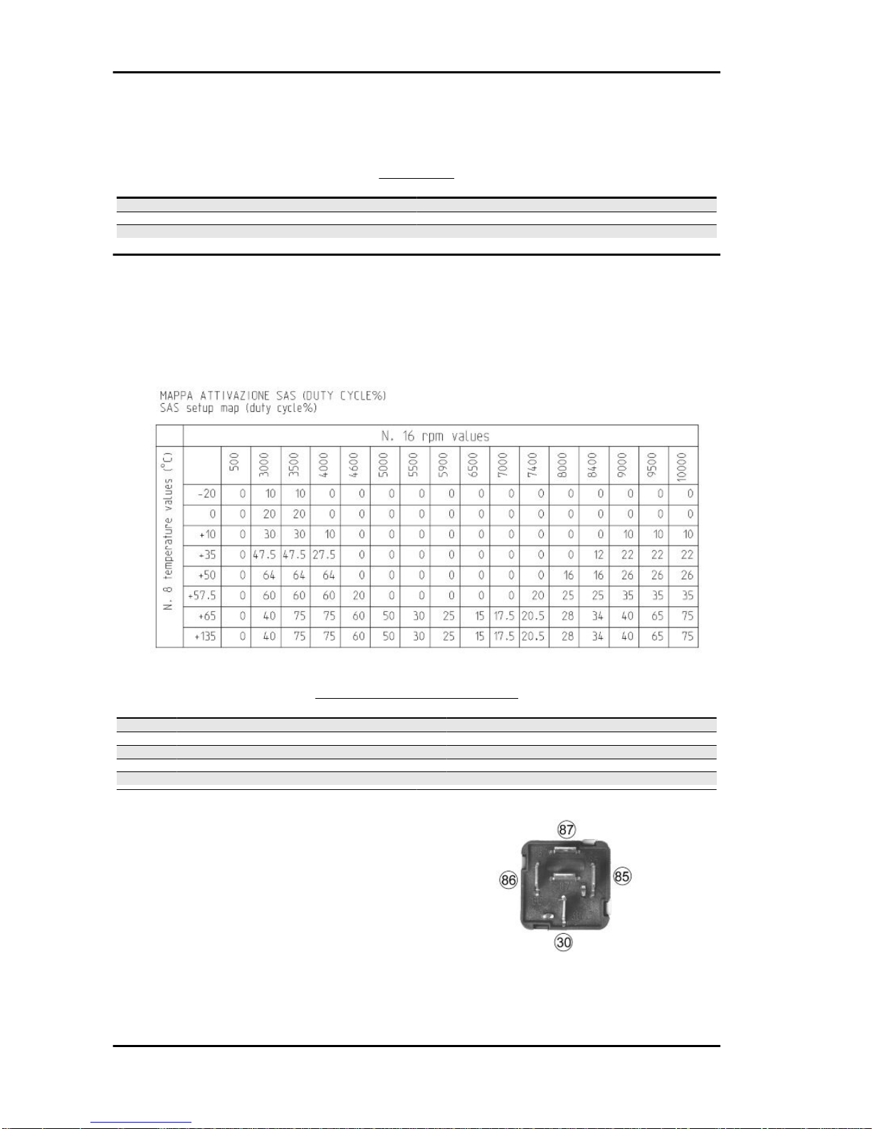
Electrical system
When the advance check is carried out with a stroboscopic gun, add 10° flywheel keying to the table
below.
ELECTRICAL COMPONENTS
Specification Desc./Quantity
1 Ignition advance reference in table
2 Spark plug NGK ER9EH-N
3 Battery 12V - 9Ah
4 Fuses 1 15A - 1 10A - 1 7.5A
5 Generator single-phase alternating current
CHECKING REMOTE CONTROLS «A» OPER-
ATING AS CIRCUIT BREAKERS
1) Check that, given regular conditions, there is no
continuity between terminals 30 and 87.
2) Apply 12V voltage to power terminals 85 and 86
of the remote control.
3) With the remote control powered, check that
there is continuity between terminals 30 and 87.
4) If these conditions are not fulfilled, the remote
control is damaged and must be replaced.
Characteristics Fly 50 4t 4v
CHAR - 10

TURN INDICATOR SWITCH
IGNITION KEY
LIGHT SWITCH
STARTER BUTTON
Fly 50 4t 4v Characteristics
CHAR - 11
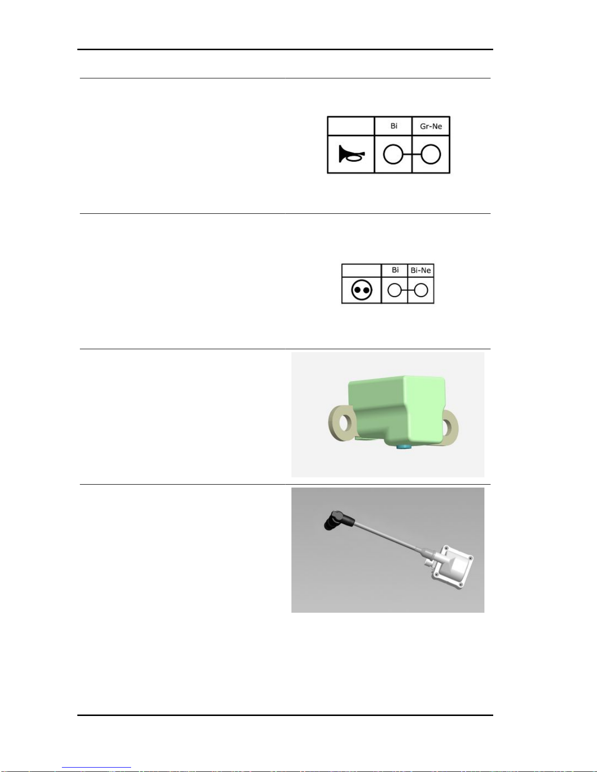
HORN BUTTON
STOP BUTTON
Resistance between green cable and ground con-
nection: approx. 170 Ohm
- Primary resistance: 0.5 to 0.6 Ohm
- Resistance between primary and ground con-
nection: infinite
- Resistance between primary and HV output: 3 to
3.6 kOhm
- Shielded cap: 5000 Ohm
Characteristics Fly 50 4t 4v
CHAR - 12
- Power: 120 W
- resistance between BLUE cable and GROUND
CONNECTION: 1 Ohm
Frame and suspensions
FRAME AND SUSPENSION
Specification Desc./Quantity
Frame Tubular steel frame
Front suspension Hydraulic telescopic fork with Ø 32-mm stem, 76 mm travel.
Rear suspension Adjustable 4-position spring preloading single shock absorber,
73 mm travel
Brakes
BRAKES
Specification Desc./Quantity
Front brake Disc brake (Ø 220 mm) with hydraulic control (lever on the far
right of the handlebar) and floating calliper.
Rear brake Ø140-mmdrumbrake withmechanical controlactivated bythe
handlebar left-side lever.
Wheels and tyres
WHEELS AND TYRES
Specification Desc./Quantity
Wheel rim type Light alloy wheel rims.
Front wheel rim 12'' x 3.00
Rear wheel rim 12" x 3.00
Front tyre Tubeless 120/70-12"
Rear tyre Tubeless 120/70 - 12"
Front tyre pressure 1.8 bar
Rear tyre pressure 2 bar
Rear wheel pressure (rider and passenger): 2.3 bar
Tightening Torques
ENGINE ASSEMBLY
Name Torque in Nm
Ignition spark plug: 10 to 15 Nm
Floating head cover screws 6 to 7
Head-cylinder stud bolt nuts 6 to 7 + 90° + 90° *
Screws fixing head and cylinder to crankcase 8 - 10
Chain tensioner pad screw 5 to 7 Nm
Timing chain tensioner central screw 5 - 6
Fly 50 4t 4v Characteristics
CHAR - 13

Name Torque in Nm
Camshaft pulley screw 12 - 14
Rocking lever axle and camshaft bearing screw 3 to 4 Nm
Rocking levers adjusting nuts: 7 to 9 Nm
Engine oil pre-filter cover: 25 - 28 Nm
Engine oil drainage cap 25 - 28
Flywheel nut 40 to 44 N.m
Stator screws 3 to 4
Pick-up screws 3 - 4
Oil pump bulkhead screw 4 - 5
Timing chain/oil pump compartment cover screws 4 to 5
Oil decantation labyrinth sheet screws 7 to 8
Oil pump sprocket gear screw 8 - 10
Screws fixing oil pump to the crankcase 5 - 6
Oil sump screws 8 - 10 Nm
Inlet manifold screw 7 - 9
Carburettor/manifold clamp screw 1.2 to 1.5
Screws fixing cables to starter motor 1.5 - 2.5
Starter motor screws 11 - 13
Transmission cover screws 11 ÷ 13
Start-up lever screw 11 to 13
Crankcase cooling cover screw 2 to 2.5
Clutch assembly nut 55 to 60
Crankshaft pulley nut 18 to 20 + 90° Nm
Driven pulley shaft nut 40 to 44 Nm
Hub oil drainage screw 3 - 5 Nm
Rear hub cap screws 11 to 13
Crankcase half union screw 8 - 10
STEERING ASSEMBLY
Name Torque in Nm
Steering upper ring nut 35 to 40
Steering lower ring nut 8 ÷ 10
Handlebar fixing screw 50 to 55
CHASSIS ASSEMBLY
Name Torque in Nm
Engine arm bolt - frame arm 40 to 45
Engine-swinging arm bolt 40 to 45
Frame-swinging arm bolt 50 to 55
Silent-block swinging arm retaining bolts 36 to 44
Side stand bolt 12 - 16
Centre stand pin 40 to 45
FRONT SUSPENSION
Name Torque in Nm
Fork bottom screw 20 ÷ 25
Front wheel axle 45 ÷ 50
Wheel axle clamp screws 6 - 7 Nm
Front mudguard to plate fixing screw 4.5 to 7
REAR SUSPENSION
Name Torque in Nm
Rear wheel axle 104 ÷ 126
Lower shock absorber clamp 40 to 45
Shock absorber/Chassis nut: 20 ÷ 25
Shock absorber to crankcase bracket fastener 20 ÷ 25
FRONT AND REAR BRAKE
Name Torque in Nm
Brake fluid pump-hose fitting 20 ÷ 25
Brake fluid pipe-calliper fitting 20 ÷ 25
Calliper tightening screw 24.5 to 27.5
Characteristics Fly 50 4t 4v
CHAR - 14
Name Torque in Nm
Disc tightening screw (Apply LOCTITE 243 medium-strength
threadlock) 8 - 12 Nm
Oil bleeding valve 8 - 12
Rear brake adjustment nut 5
Overhaul data
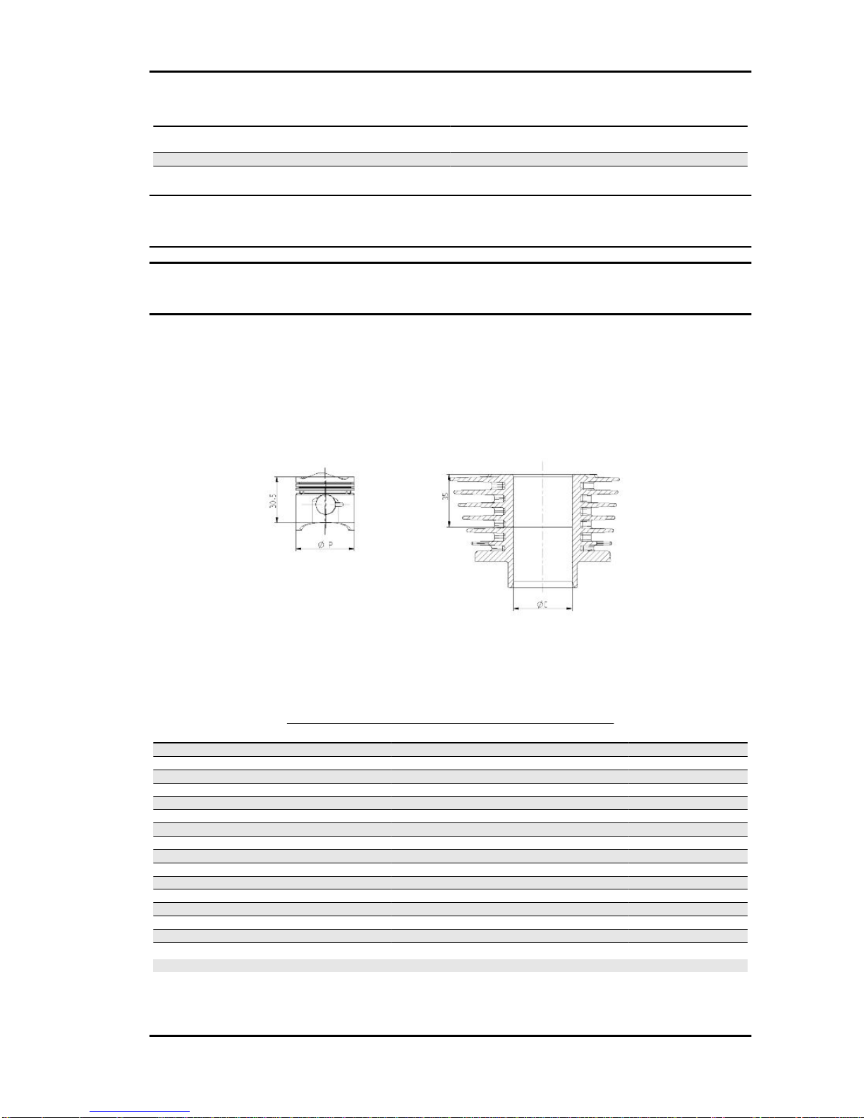
Assembly clearances
Cylinder - piston assy.
COUPLING BETWEEN PISTON AND CYLINDER
Name Initials Cylinder Piston Play on fitting
Cylinder A 38.993 to 39.000 38.954 to 38.961 0.032 to 0.046
Cylinder B 39.000 to 39.007 38.961 to 38.968 0.032 to 0.046
Piston C 39.007 to 39.014 38.968 to 38.975 0.032 to 0.046
Piston D 39.014 to 39.021 38.975 to 38.982 0.032 to 0.046
Cylinder 1st oversize A1 39.193 to 39.200 39.154 to 39.161 0.032 to 0.046
Cylinder 1st oversize B1 39.200 to 39.207 39.161 to 39.168 0.032 to 0.046
Piston 1st oversize C1 39.207 to 39.214 39.168 to 39.175 0.032 to 0.046
Piston 1st oversize D1 39.214 to 39.221 39.175 to 39.182 0.032 to 0.046
Cylinder 2nd oversize A2 39.393 to 39.400 39.354 to 39.361 0.032 to 0.046
Cylinder 2nd oversize B2 39.400 to 39.407 39.361 to 39.368 0.032 to 0.046
Piston 2nd oversize C2 39.407 to 39.414 39.368 to 39.375 0.032 to 0.046
Piston 2nd oversize D2 39.414 to 39.421 39.375 to 39.382 0.032 to 0.046
Cylinder 3rd oversize A3 39.593 to 39.600 39.554 to 39.561 0.032 to 0.046
Cylinder 3rd oversize B3 39.600 to 39.607 39.561 to 39.568 0.032 to 0.046
Piston 3rd oversize C3 39.607 to 39.614 39.568 to 39.575 0.032 to 0.046
Piston 3rd oversize D3 39.614 to 39.621 39.575 to 39.582 0.032 to 0.046
N.B.
THE PISTON MUST BE INSTALLED WITH THE ARROW FACING TOWARDS THE EXHAUST SIDE,
THE PISTON RINGS MUST BE INSTALLED WITH THE WORD «TOP» OR THE STAMPED MARK
FACING UPWARDS.
Fly 50 4t 4v Characteristics
CHAR - 15
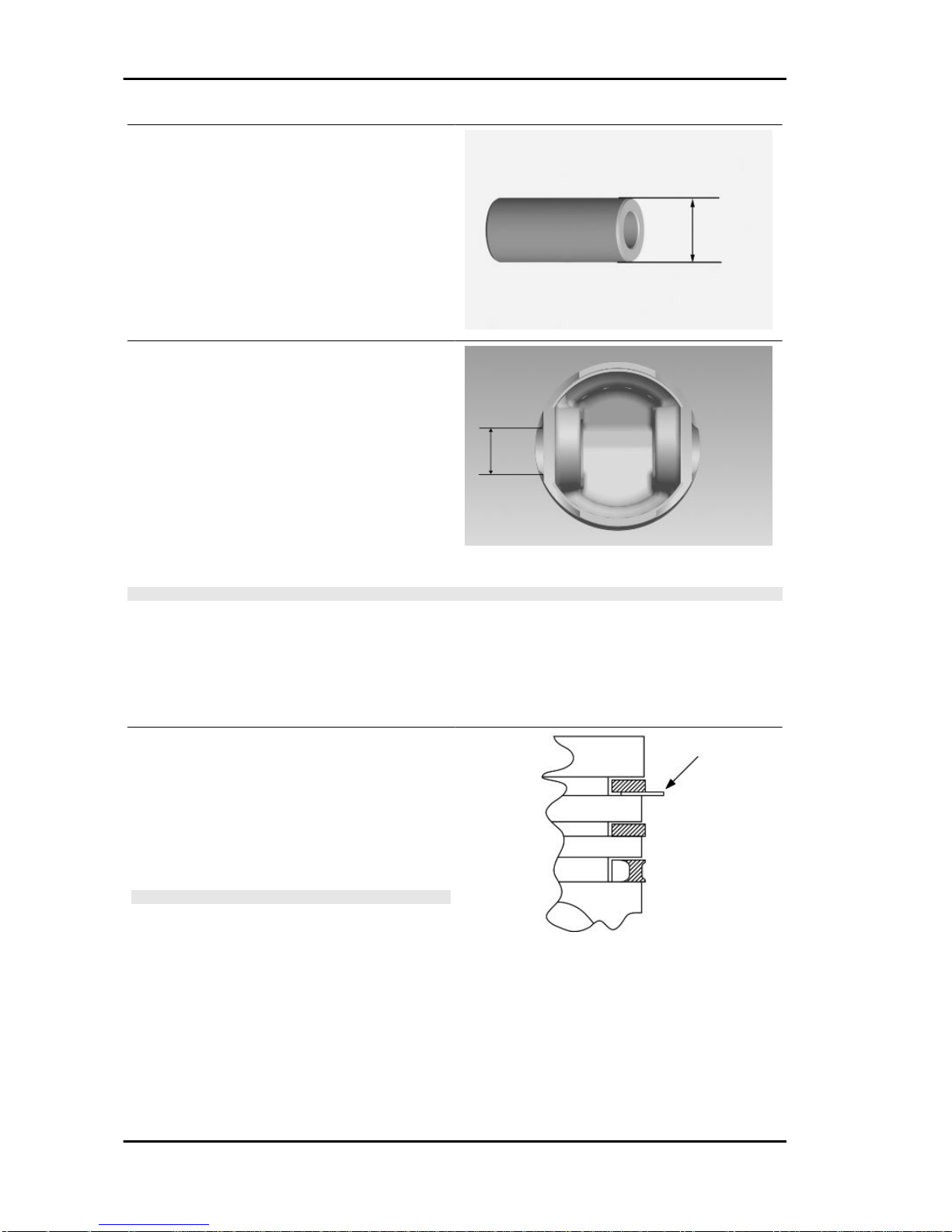
- Measure the outer diameter of the gudgeon pin.
Characteristic
Pin outside diameter
13 +0 -0.004 mm
Minimum admissible diameter gudgeon pin
12.990 mm
- Measure the diameter of the bearings on the pis-
ton.
Characteristic
Pin seat diameter
13 +0.005 + 0.010 mm
- Calculate the piston pin coupling clearance.
N.B.
THE PIN HOUSINGS HAVE 2 LUBRICATION CHANNELS. FOR THIS REASON, MEASUREMENT
MUST BE MADE ACCORDING TO THE PISTON AXIS
Characteristic
Standard clearance
0.005 to 0.014 mm
- Carefully clean the seal housings.
- Measure the coupling clearance between the
sealingringsandthe pistongrooves usingsuitable
sensors, as shown in the diagram.
- If the clearance is greater than that indicated in
the table, replace the piston.
N.B.
MEASURE THE CLEARANCE BY INSERTING THE BLADE
OF THE FEELER GAUGE FROM THE SECOND SEAL RING
SIDE.
Fitting clearance
Top piston ring - standard coupling clearance
0.03 to 0.065 mm Top piston ring - maximum clear-
ance allowed after use 0.07 mm Middle piston
ring - standard coupling clearance 0.02 to 0.055
mm Middle piston ring - maximum clearance al-
lowed after use0.06 mm oil scraper ring - stand-
ard coupling clearance0.04 to 0.16 mm oil scraper
Characteristics Fly 50 4t 4v
CHAR - 16
ring - maximum clearance allowed after use
0.17 mm
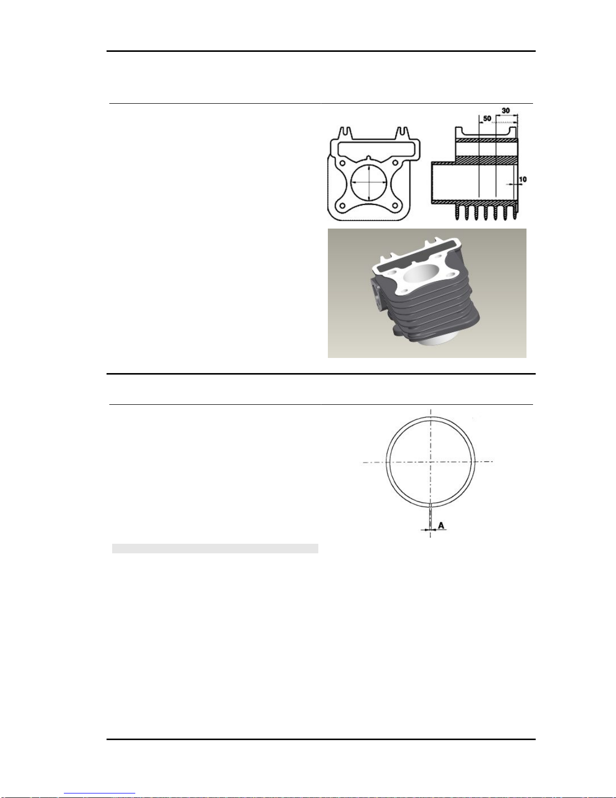
- Using a bore meter, measure the inner cylinder
diameter at three different points according to the
directions shown in the figure.
- Check that the coupling surface with the head is
not worn or misshapen.
- Pistons and cylinders are classified into catego-
ries based on their diameter. The coupling is car-
ried out in pairs (A-A, B-B, C-C, D-D).
Characteristic
Maximum allowable run-out:
0.001 over 0.05 mm
Piston rings
- Alternately insert the three sealing rings into the
cylinder, in the area where it retains its original di-
ameter. Using the piston, insert the rings perpen-
dicularly to the cylinder axis.
- Measure the opening, see figure, of the sealing
rings using a thickness gauge.
- If any measurements are greater than specified,
replace the piston rings.
N.B.
BEFOREREPLACING ONLYTHEPISTONRINGS, ENSURE
THAT THE CLEARANCE BETWEEN THE PISTON RINGS
AND THE PISTON RING GROOVES, AND BETWEEN THE
PISTON AND THE CYLINDER, IS AS SPECIFIED. IN ANY
CASE, NEW PISTON RINGS USED IN COMBINATION WITH
A USED CYLINDER MAY HAVE DIFFERENT BEDDING
CONDITIONS THAN THE STANDARD.
Fly 50 4t 4v Characteristics
CHAR - 17

SEALING RINGS
Name Description Dimensions Initials Quantity
1st Compression ring 39 x 1 A 0.08 to 0.20
2nd Compression ring 39 x 1 A 0.05 to 0.20
Oil scraper ring 39 x 2 A 0.20 to 0.70
1st Compression ring
1st Oversize 39.2 x 1 A 0.08 to 0.20
2nd Compression ring
1st Oversize 39.2 x 1 A 0.05 to 0.20
Oil scraper ring 1st
Oversize 39.2 x 2 A 0.20 to 0.70
1st Compression ring
2nd Oversize 39.4 x 1 A 0.08 to 0.20
2nd Compression ring
2nd Oversize 39.4 x 1 A 0.05 to 0.20
Oil scraper ring 2nd
Oversize 39.4 x 2 A 0.20 to 0.70
1st Compression ring
3rd Oversize 39.6 x 1 A 0.08 to 0.20
2nd Compression ring
3rd Oversize 39.6 x 1 A 0.05 to 0.20
Oil scraper ring 3rd
Oversize 39.6 x 2 A 0.20 to 0.70
Characteristics Fly 50 4t 4v
CHAR - 18

Crankcase - crankshaft - connecting rod
AXIAL CLEARANCE BETWEEN CRANKSHAFT AND CRANKCASE
Name Description Dimensions Initials Quantity
Half-shaft, transmission
side 14 +0 -0.005 A
Flywheel-side half shaft 16 +0 -0.005 B
Connecting rod 14.8 +0.05 -0 C
Spacer tool 45.00/Fits andclearan-
ces D = 0.15 to 0.30 E
Characteristic
Clearance between crankshaft and connecting rod
A = 0.15 to 0.30 mm
Fly 50 4t 4v Characteristics
CHAR - 19
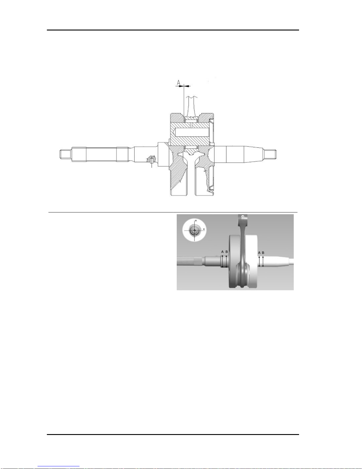
Measure the bearings along X and Y axes
Characteristic
Crankshaft bearing, transmission side
20 -0.012 -0.025 mm
Crankshaft bearing, flywheel side
17 +0.007 0 mm
- Check that the driving shaft cone, the tab seat, the oil seal capacity, the toothed gear and the threaded
tangs are in good working order.
- In case of failures, replace the crankshaft.
Specific tooling
020074Y Support base for checking crankshaft alignment
Characteristics Fly 50 4t 4v
CHAR - 20
Table of contents


