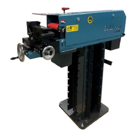
Scotchman AL100U-01 User manual

www.scotchman.com
MODELS
AL100U-01
AL100U-02
PIPE NOTCHER
GRINDER
VERSION 1 - JULY 2019
SCOTCHMAN INDS. - 180 E. HWY 14 - PO BOX 850 - PHILIP, SD 57567 PHONE: 1-605-859-2542

PAGE 2
MODEL - AL100U-01
AL100U-01 (2) Hand Lever Feed Handles

PAGE 3
MODEL - AL100U-02
AL100U-02 (2) Handwheels & Feed Handle
NOTE: The larger hand wheel and it's spindle must be removed to use the handle.

PAGE 4
TUBE & PIPE GRINDER NOTCHERS
Create a perfect notch in seconds using
Scotchman's line of tube and pipe notching
equipment. These notchers are ideal for steel
and stainless steel (consult factory) tube and
pipe construction, hand railings, gates and
fences, race car frames and roll cages, marine
arches, railing, furniture frames, and stainless
plumbing for restaurant or dairy.
Scotchman's notching equipment requires no
costly dies, hole saws, grinding wheels or torch
flame cutting.
Thank You for your purchase of Scotchman
products - We appreciate your business!!
SCOTCHMAN INDS. - 180 E US HWY 14 - PO BOX 850 - PHILIP, SD 57567 Call: 1-605-859-2542

TABLE OF CONTENTS
1.0 INTRODUCTION 7
2.0 SAFETY PRECAUTIONS 7
3.0 MACHINE DECALS 9
4.0 INSTALLATION AND SET UP
10
MACHINE START-UP5.0
23
29
NOTCHING CAPACITIES
4.2
7.0
6.0
23
MACHINE OPERATIONS
4.1
SECTION DESCRIPTION PAGE #
11
2.1 Warranty 8
13
Warning Symbols
Assembling Machine & Moving
11
4.3
4.4
16
4.5 Wiring Diagrams
15
18
15
5.1 Machine Controls & Adjustments
23
23
6.2 Drive for the Grinding Belt
24
6.3 Securing a Tubing Section
25
6.4 Angle Adjustment
26
6.1 Starting and Stopping Belt
23
6.5 Depth Stop
26
6.6 Length Stop
28
7.1 Angled Notching Capacity
19
Physical Dimensions
3.1
Electrical Requirements
Machine Identification
6.7 Notching the Tubing
6.8 Deburring
SCOTCHMAN INDS. - 180 E US HWY 14 - PO BOX 850 - PHILIP, SD 57567 Call: 1-605-859-2542
PAGE 5
(Contactors, Overloads & Motors)

PAGE 6
30
8.3 Setting Belt Tension 34
8.1 Belt Tension 31
8.2 Changing The Roller 32
CHANGING ROLLERS AND BELT8.0
9.3 Roller Support Installation 39
8.5 Adjustment Of Grinding Roller 36
8.4 Setting The Belt Tracking 35
37
37
9.2 Roller Support Kit Location 38
9.4 Roller Support Kit Start Up 41
9.5 Roller Holder 41
AVAILABLE OPTIONS9.0
9.1 Roller Support Kit
AVAILABLE ROLLERS10.0 43
AVAILABLE GRINDING BELTS11.0 43
AL100U-01 & COMMON PARTS LIST12.0 44
AL100U-02 PARTS LIST 13.0 47
SCOTCHMAN INDS. - 180 E US HWY 14 - PO BOX 850 - PHILIP, SD 57567 Call: 1-605-859-2542
OPTIONAL BACK GAUGE 49
OPTION

1.0 INTRODUCTION
Tube & Pipe Notch Grinders
Scotchman Tube & Pipe Grinder/Notchers are strong, accurate machines that operate at high speeds.
Stainless-steel sections and pipes can be machined problem free, at high speed without grinding burrs
or heat discoloration. The grinding rollers can be changed without tools in just seconds, saving time
and money! The grinding belt can also be changed easily from one side of the machine. Once the
sections and pipes have been ground, they can be deburred using the handy deburring table on top of
the machine.
Scotchman machines with lever operation are suitable for left and right-handed operators. The pipe
grinder/notchers offer trouble-free, accurate, quick and efficient machining of tubes and pipes for
many years; and are backed by a 3-year warranty.
FEATURES:
Fast, strong and accurate
Ideally suited for grinding stainless quickly
Fitted with grinding rollers that can be changed in seconds
Equipped with a handy deburring table
Suitable for both left & right-handed operation
Grinds tube and pipe at every angle between 30 degrees and 90 degrees
3-Year Warranty
OPTIONAL BACK GAUGE - SEE PAGE 49
2.0 SAFETY PRECAUTIONS
1. The operators of this machine must be qualified and well trained in the operation of the machine.
The operators must be aware of the capacities of the machine and the proper use of the holding
device and the guards provided with the machine. This manual is not intended to teach untrained
personnel how to operate machinery.
2. All of the guards, and awareness barriers must be installed on the machine and kept in good
working order. Promptly replace worn or damaged parts with the correct authorized parts.
3. Never place any part of your body into any of the machine’s moving parts or hold devices.
4. Wear the appropriate personal protective equipment. This machine grinds metal and creates
abrasive and metallic particles so Safety Glasses are required at all times!! Whether operating,
setting up or observing this machine in operation, Safety Glasses are a requirement.
5. Since pieces of metal with sharp edges are processed on this machine, the operator should also
wear steel-toed shoes and leather gloves.
6. Strictly comply with all warning labels and decals on the machine. Never remove any of the labels
and replace worn or damaged labels promptly.
7. Always disconnect and lock out the power when performing maintenance work or repairs on this
machine.
8. Replace sanding belt when needed. Never operate this machine with a sanding belt that is worn out.
The excessive pressure required to notch a tube with a worn out sanding belt can damage roller and
cut the sanding belt.
PAGE 7

8. Practice good housekeeping. Keep the area around the machine clear and well lit. Do not obstruct
the operator’s position by placing anything around the machine that would impede the operator’s
access to the machine.
9. Never modify this machine in any way without the written permission of the manufacturer.
10. Never leave this machine running unattended.
11. Never operate any of the work stations from a sitting or kneeling position.
12. Always be aware of what others around you are doing at all times.
13. Set up a program of routine inspections and maintenance for this machine. Make all repairs and
adjustments in accordance with the manufacturer’s instructions.
2.1 WARRANTY
Scotchman Industries, Inc. will, within three (3) years of the date of purchase, replace F.O.B. the factory
or refund the purchase price for any goods which are defective in materials or workmanship, provided
the buyer returns the warranty registration card within thirty (30) days of the purchase date and, at the
seller’s option, returns the defective goods freight and delivery prepaid to the seller, which shall be the
buyer’s sole and exclusive remedy for defective goods.
Hydraulic and electrical components are subject to their respective manufacturer’s warranties.
This warranty does not apply to machines and/or components which have been altered, changed or
modified in any way or subjected to abuse and abnormal use, inadequate maintenance and lubrication
or subjected to use beyond the seller’s recommended capacities and specifications.
In no event shall the seller be liable for labor cost expended on such goods or consequential damages.
The seller shall not be liable to the purchaser or any other person for loss or damage directly or
indirectly arising from the use of the goods or from any other cause. No officer, employee or agent of the
seller is authorized to make any oral representations or warranty of fitness or to waive any of the
foregoing terms of sale and none shall be binding on the seller.
Any electrical changes made to the standard machine due to local electrical code variation must be paid
by purchaser. As we constantly strive to improve our products, we reserve the right to make changes
without notification.
PAGE 8
ALMIby

PAGE 9
MODEL - AL100U-02 Shown
FIGURE 1
1
Qty Part # Description
1 A050.00024 Safety Sticker 8.5 x 8cm
2 1 A050.00025 Sticker Door 13 x 5cm
3 1 N/A Belt Size Decal
4 1 N/A CE Sticker
Item
3.0 MACHINE DECALS
2
3
RED GREEN
ALMI Motor
Type AL 100U-02 Volt 230
Hz. 60
l/min 3420
Weight 2102011
Sr.No.
KEEP LID CLAP CLOSED
WHILE BELT IS IN MOTION
FAILURE TO COMPLY
COULD RESULT
IN SERIOUS
BODILY
INJURY
CAUTION
WHEN OPERATING
THIS MACHINE
ALWAYS WEAR
EYE PROTECTION
READ OWNERS
MANUAL
ALWAYS WEAR
EAR PROTECTION
ALMI
KEEP LID CLAP CLOSED
WHILE BELT IS IN MOTION
FAILURE TO COMPLY
COULD RESULT
IN SERIOUS
BODILY
INJURY
R929 < Ø30mm < RX66
Ø30mm
ALMI Motor
Type AL 100U-02 Volt 230
Hz. 60
l/min 3420
Weight 2102011
Sr.No.
RED GREEN
ALMI Motor
Type AL 100U-02 Volt 230
Hz. 60
l/min 3420
Weight 2102011
Sr.No.
KEEP LID CLAP CLOSED
WHILE BELT IS IN MOTION
FAILURE TO COMPLY
COULD RESULT
IN SERIOUS
BODILY
INJURY
R929 < Ø30mm < RX66
Ø30mm
1
4

PAGE 10
3.1 WARNING SYMBOLS
PICTOGRAM 1:
READ OWNERS MANUAL FIRST!!
PICTOGRAM 2:
USE OF EYE PROTECTION REQUIRED!!
PICTOGRAM 3:
USE OF HEARING PROTECTION REQUIRED!!
PICTOGRAM 4:
KEEP LID CLAP CLOSED
WHILE BELT IS IN MOTION!!
BEFORE OPERATING THIS MACHINE
Strictly comply with all warning labels and decals on the machine. Never
remove any of the labels and replace worn or damaged labels promptly!!

4.0 INSTALLATION AND SET UP
CAUTION: THIS SECTION (4.0 to 5.0) DISCUSSES INSTALLATION AND SET-UP
PROCEDURES. PLEASE READ THOROUGHLY BEFORE OPERATING THIS MACHINE.
►
4.1 PHYSICAL DIMENSIONS SEE FIGURE 2 ► ◄
1Machine Height 45-1/4 114.9
250-3/4 128.9
3
4
5
6
7
8
9
26-1/8 66.4
34-1/2 87.6
24-1/4 61.6
Length
7-1/4 18.4
Width
Front from Base
460 LBS. 209 KG.
19-1/4 48.9
INCHES CM DESCRIPTION
ITEM
PAGE 11
Base Length
19-1/4 48.9
Base Width
Base Height
Weight
Rear from Base

PAGE 12
6
23
5
78
FIGURE 2
4
1
RED GREEN
ALMI Motor
Type AL 100U-02 Volt 230
Hz. 60
l/min 3420
Weight 2102011
Sr.No.
KEEP LID CLAP CLOSED
WHILE BELT IS IN MOTION
FAILURE TO COMPLY
COULD RESULT
IN SERIOUS
BODILY
INJURY
R929 < Ø30mm < RX66 Ø30mm

4.2 ASSEMBLING MACHINE & MOVING
PAGE 13
ASSEMBLING OVERVIEW
This grinder/notcher machine is shipped unassembled in a wooden crate.
There are basically four parts. See FIGURE 3 on the next page.
FOOT PLATE: This is a 1 inch thick by 19-1/2 inch square metal plate that sits on the floor.
SUPPORT PILLAR: This is the rectangular "box" that mounts to the Base with 4 bolts and washers.
PLATE: This is a flat rectangle shaped plate that mounts on top of the Column.
GRINDER: This is the main part of the machine. It mounts on top of the Column and Plate
with two bolts and washers. It has a "Lifting Eye" that is used for moving it.
ASSEMBLY & MOVING BOTH MODELS
• Remove loose components from the packaging. Inside the support pillar you will find a box with any
ordered grinding belts and grinding rollers, the grinding waste container, the ball handle, the handle,
and the attachment hardware.
• Remove the two attachment bolts with which the universal pipe notcher is attached to the bottom
plate of the packaging.
• Remove the wood screws with which the support pillar and foot plate are attached to the crate.
• Remove the support pillar from the packaging and bolt them together with (4) bolts and washers.
• Remove the machine from the packaging. To do so, use the Lifting Eye Shown in FIGURE 3. Use the
proper lifting equipment as this machine weighs 200 kg (440 lbs).
• Open the side cover of the machine and attach the machine to the support pillar - with the plate in
between them - using two M12 hex bolts.
• Slide the grinding waste container under the machine.
• Install the included ball handle on the front of the cross support.
•Install the included lower handle under the cross support.
NOTE: The ALU100-02 is operated with (2) round aluminum hand-wheels. However,
the lower handle for under the cross support is supplied with this machine. The larger in
feed wheel and it's spindle must be removed in order to use it.

FIGURE 3
PAGE 14
LIFTING EYE
(Motor-Side of Machine)
BALL
HANDLE
LOWER
HANDLE
FRONT OF AL100U-01 MACHINE
GRINDER
PLATE
WASTE
CONTAINER
NOTE:
Longer
Spacer is
for Slots
201212
M10x35
214012
201212
M10x35
214012
201212
M10x35
214012
201212
M10x35
214012
201212
M10x35
214012
201212
M10x35
214012
MACHINE IS TOP HEAVY!!
Use Only LIFTING EYE to move machine
Use Extreme Caution when moving
SUPPORT
PILLAR
FOOT
PLATE
SMALL
ALUMINUM
HAND-WHEEL
(side)
LARGE
ALUMINUM
HAND-WHEEL
(front)
FRONT OF AL100U-02
MACHINE
AL100U-02
NOTE: The larger hand
wheel and it's spindle must
be removed to use this
in-feed handle.

These machines have a white "CE" Decal on them that Identifies the machine and has other
important information such as machine Voltage, Hz, RPM, Weight & Year of Manufacture.
This Decal is located between the START STOP buttons and EMERGENCY STOP button on
the Support Pillar of the machine. Sect. 3.0 Figure 1 details the location. You will need this
information for ordering parts or service for the machine.
An example of what the CE Decal looks like below:
4.3 MACHINE IDENTIFICATION
PAGE 15
CAUTION: TO PREVENT DAMAGE TO THE MOTOR AND DANGER TO THE OPERATOR,
ALL ELECTRICAL CONNECTIONS MUST BE MADE BY A LICENSED ELECTRICIAN.
The AL100U-01 and AL100U-02 are available 240V and 440V Three Phase and 240V Single Phase. To
insure satisfactory machine performance, the supply voltage should be +/- 10% of the motor voltage
rating. Check the motor data tag for full load current requirements. The electrical diagram for the
motor is inside the cover of the motor box.
For electrical supply lines ten feet (3 m) or shorter, we recommend at least 12 and preferably, 10 gauge
wire. For longer supply lines, use at least 10 gauge and preferably, 8 gauge. We do not recommend
supply lines longer than twenty five feet (7.5 m).
POWER REQUIREMENTS:
Motor frame: 100L
MOTOR VOLTAGE FULL LOAD AMPS
230 10.6 Amps
460 6.1 Amps
230 (Single phase) 17.8 Amps
Motor power rating: Approx. 4hp Speed: 3500 RPM
KVA power rating: 3.4 KVA at 60 HZ.
Starting Current: 210% Full Load
4.4 ELECTRICAL REQUIREMENTS
ALMI Motor
Type AL 100U-02 Volt 230
Hz. 60
l/min 3420
Weight 2102011
Sr.No.
Additionally, the machine serial number is
located on top of the tube clamp on the left side.

FIGURE 4
PAGE 16
4
3
TO MOTOR*
LC1D18
SCHNEIDER
LRD32
SCHNEIDER
LINE POWER AL-100U
230V Single Phase
4
3
2
1
EMER.
STOP
START
BUTTON
23
32
28.5
L1 L2
(N)
* Follow Instruction
Sheet In Motor Box
If Provided
SET OVERLOAD TO
FLA SHOWN ON
MOTOR PLATE
4
3
TO MOTOR*
LC1D18
SCHNEIDER
LRD32
SCHNEIDER
LINE POWER AL-100U
230V Single Phase
4
3
2
1
EMER.
STOP
START
BUTTON
23
32
28.5
L1 L2
(N)
* Follow Instruction
Sheet In Motor Box
If Provided
SET OVERLOAD TO
FLA SHOWN ON
MOTOR PLATE
DESCRIPTION
011435
011436
PART #
OVERLOAD 230V
CONTACTOR WITH COIL 230V 1PH.
E030.00001 MOTOR 230V 1PHASE 60HZ 3KW
4.5 WIRING DIAGRAMS
(Contactors, Overloads & Motors)

PAGE 17
230V 460V
Brown
Black
Blue
4
3
LC1D12
SCHNEIDER
LRD 12
SCHNEIDER
LINE POWER
AL-100U Three Phase
4
3
2
1
EMER.
STOP
START
BUTTON
6.5
8
6
5.5
7
Brown
Black
Blue
* Follow Instruction
Sheet In Motor Box
If Provided
Brown
TO MOTOR*
SET OVERLOAD TO
FLA SHOWN ON
MOTOR PLATE
011420
011421
CONTACTOR WITH COIL 460V
OVERLOAD 460V
MOTOR 230/460V 3PHASE 60HZ 3KW
460V THREE PHASE
011432
011433
CONTACTOR WITH COIL 230V
OVERLOAD 230V
E030.00002 MOTOR 230/460V 3PHASE 60HZ 3KW
230V THREE PHASE
E030.00002
DESCRIPTIONPART #
DESCRIPTIONPART #
NOTE: Swap (2)
Incoming
Power Wires to
change Rotation

This machine is equipped with (3) switches located on the right side of the Support Pillar.
The Green is the START Button and next to it is the Red STOP Button.
Below them is the larger EMERGENCY STOP Button.
REFER TO FIGURE 6 BELOW
To start the machine the EMERGENCY STOP Button must be pulled out. Push the Green START
Button to start the machine. Push the Red STOP button to stop the machine. The EMERGENCY
STOP Button can also be used to stop the machine, but must be pulled back out in order to restart
the machine.
FIGURE 6
EMERGENCY STOP
RED
STOP
GREEN
START
ALMI Motor
Type AL 100U-02 Volt 230
Hz. 60
l/min 3420
Weight 2102011
Sr.No.
5.0 MACHINE START-UP
PAGE 18
RED GREEN
ALMI Motor
Type AL 100U-02 Volt 230
Hz. 60
l/min 3420
Weight 2102011
Sr.No.
KEEP LID CLAP CLOSED
WHILE BELT IS IN MOTION
FAILURE TO COMPLY
COULD RESULT
IN SERIOUS
BODILY
INJURY
R929 < Ø30mm < RX66 Ø30mm

MODEL - AL100U-01
REFER TO FIGURE 7
1. Allen key, 8mm, with handle; for securing rotatable tubing clamp, for securing
standard stopper, and for adjustment of grinding belt.
2. Allen bolt (may be a knob) for opening and closing side cover. Use key with handle (1).
3. Allen bolt for securing grinding belt. Use key with handle (1).
4. Ball Handle for adjusting tubing clamp into and away from grinding roller.
5. Handle for adjusting tubing clamp side to side to grinding roller.
6. Handle for clamping work-piece in tubing clamp.
7. Allen bolt for securing rotatable clamp. There is another bolt (not shown) in the center of the
clamp that also must be loosened & tightened to adjust the clamp. Use key with handle (1).
5.1 MACHINE CONTROLS & ADJUSTMENTS
PAGE 19
ALMIby

MODEL - AL100U-01
FIGURE 7
PAGE 20
132
4
5
6
7
This manual suits for next models
1
Table of contents
Other Scotchman Grinder manuals
