SCOV SV800 Series User manual
SV800 Series
Intelligent vector inverter
Users’Manual
Ver:1.0-01
Shenzhen SCOV Electric Technologies Co., Ltd.

SV800/SV800A User Manual Version:V1.0-01
Foreword
Thank you for purchasing and using SCOV SV800 series intelligent vector frequency inverter.
The SV800 series inverter is a kind of high-performance intelligent frequency inverter. We have
made great breakthrough in dynamic response, speed-stabilizing precision, torque precision,
intelligent start-up, weak magnetic control features and so on and made them reach international
top technology level. After combined with the application characteristics of some new industries,
the applicability and the industry design of the products are further strengthened, so it can better
meet the requirements of all kinds of transmission applications.
After careful study, SCOV found that if we want to achieve a breakthrough in the core
algorithm, we must systematically study the solution, especially perform algorithmically
accurate calculations for the nuances of the theoretical model of the motor and the actual motor
parameters, the nonlinear loss of the drive circuit and the loss of the connecting wire.
The practice has proved that the implementation of these methods has achieved a surprising
result and has reached even surpassed the level of international first-class brands on a number of
core indicators, which indicates that the era of truly cost-effective and high-performance
frequency inverter has arrived.
No professional parameter adjustment required, a high-performance drive can be realized only
after self-learning or auto-tuning , so we re-define SV800 series inverter as the intelligent vector
frequency inverter.
Born for intelligence, SCOV will work with you to move forward!

Content
1 Safety information and precautions ...................................................................................1
1.1 Safety precautions...................................................................................................1
1.1.1 Safety precautions before installation ..........................................................1
1.1.2 Safety precautions for transporting and installation.....................................1
1.1.3 Safety precautions for wiring.......................................................................2
1.1.4 Safety precautions for debugging and operation..........................................2
1.1.5 Safety precautions for maintenance and rejection........................................3
1.1.6 Other safety precautions...............................................................................3
2 Product Introduction..........................................................................................................5
2.1 Model and specifications ........................................................................................5
2.1.1 Nameplate explanation.................................................................................5
2.1.2 Designation Rules of SV800/SV800A models.............................................6
2.1.3 Components name of the frequency inverter................................................7
2.1.4 Product models and specifications...............................................................9
2.1.5 Heavy load application and de-rating use of frequency inverter................10
2.2 Description of control performance ......................................................................13
3 Mechanical Installation....................................................................................................19
3.1 Mechanical Installation.........................................................................................19
3.1.1 Installation Environment............................................................................19
3.2 Installation direction and space.............................................................................20
3.2.1 Installation space........................................................................................20
3.2.2 Installation direction ..................................................................................22
3.3 Installation Guidance............................................................................................23
3.3.1 Wall-mounted Installation..........................................................................23
3.4 Disassembly and installation of keyboard.............................................................24
3.4.1 Disassembly of the keyboard .....................................................................24
3.4.2 Installation of the keyboard........................................................................24
3.5 Disassembly and installation of SV800 cover.......................................................25
3.5.1 Disassembly and installation of SV800 cover (plastic housing) ................25
3.5.2 Disassembly and installation of SV800 cover (sheet metal housing).........26

3.6 SV800 appearance and installation dimensions....................................................27
3.7 Keyboard appearance and installation dimensions................................................31
4 Electrical wiring and precautions.....................................................................................33
4.1 Main circuit electrical wiring................................................................................33
4.1.1 Arrangement and definition of main circuit terminals................................33
4.1.2 Main circuit wiring precautions .................................................................36
4.1.3 Installation size and wire selection of power terminals..............................38
4.2 Description of control terminals ...........................................................................40
4.2.1 Function descriptions of the switching terminals connection.....................44
4.2.2 Wiring method of frequency inverter electric control circuit .....................46
4.2.3 Wiring description of control signal terminals...........................................47
4.3 EMC .....................................................................................................................49
4.3.1 Definitions of related terms........................................................................49
4.3.2 Introduction of EMC standards..................................................................50
4.3.4 Installation of EMC input filter on Power supply input .............................50
4.3.5 Installation of AC input reactor on power supply input .............................50
4.3.6 Installation of AC output reactor on frequency inverter output..................50
4.3.7 Installation of external DC reactor.............................................................51
4.3.8 Shielded cable............................................................................................51
5 Introduction of operation and running .............................................................................55
5.1 Confirmation before running ................................................................................55
5.1.1 Wiring check of the frequency inverter......................................................55
5.1.2 The setting and debugging check of the frequency inverter.......................57
5.2 Instructions of the keyboard using........................................................................59
5.2.1 Function and name of each part .................................................................59
5.2.2 Description of LED indicators ...................................................................60
5.2.3 Level structure of the keyboard display functions......................................62
5.2.4 Examples of the keyboard using ................................................................63
5.2.5 Operation of monitoring parameters ..........................................................66
5.2.6 Connection mode of external keyboard......................................................67
5.3 Induction motors parameters self-learning............................................................68
5.3.1 Induction motor parameters self-learning method and procedure..............68

5.3.2 Preparation before induction motor self-learning.......................................72
5.3.3 Instructions of induction motor DC self-learning mode.............................73
5.3.4 Instructions of induction motor Full-mode self-learning............................74
5.3.5 Instructions of the second induction motor self-learning...........................76
5.3.6 Status display and fault description of induction motor self-learning........79
5.4 Inverter model, carrier frequency and control mode settings................................81
5.4.1 The model setting and modification...........................................................81
5.4.2 Carrier frequency setting and modification................................................81
5.4.3 The control mode setting and modification................................................82
5.5 Speed control and regulator parameter debugging................................................82
5.5.1 Speed control indicator description............................................................82
5.5.2 Setting of motor rotation inertia.................................................................83
5.5.3 Speed control proportional coefficient and integral time constant setting..83
5.5.4 The setting of speed observer and torque observer ....................................84
5.6.5 The setting of speed variable structure control parameters ........................85
5.5.6 Switching of speed control proportional coefficient ..................................85
6 Function Parameters List .................................................................................................86
6.1 Reading method of function parameters list..........................................................86
6.1.1 Representation of icons in parameters list..................................................86
6.1.2 Keyboard LED display character and letter correspondence table.............86
6.2 The type of parameters..........................................................................................87
6.2.1 Parameters Type Correspondence Table.....................................................87
6.3 Function Parameters List ......................................................................................89
7 Detailed function description.........................................................................................135
7.1 System parameters A group ................................................................................135
7.1.1 Basic parameter A0 group........................................................................135
7.2 b:Induction motor parameters.............................................................................141
7.2.1 b0: Induction motor basic parameters ......................................................141
7.2.2 b1: The first induction motor parameters group.......................................143
7.2.3 b2:The second induction motor parameters group ...................................146
7.3 d: debugging and controlling parameters............................................................147
7.3.1 d0: speed control debugging parameters..................................................147

7.3.2 d1: Command input selection...................................................................148
7.3.3 d2: Operating module control parameters................................................154
7.3.4 d3:Torque control module parameters......................................................162
7.3.5 d4:V/F control mode parameters..............................................................162
7.4 E: Acc./Dec. curve setting parameters ................................................................165
7.4.1 E0:The upper and low limit speed/ frequency..........................................165
7.4.2 E1:Speed/ frequency instructions.............................................................165
7.4.3 E2: Acc./Dec. time selection ....................................................................165
7.4.4 E3: Jump Speed and UP/DOWN .............................................................168
7.5 F:Application function parameters group ...........................................................173
7.5.1 F0: PID control parameters......................................................................173
7.5.2 F1: Constant pressure water supply .........................................................178
7.5.3 F2:Paper towel equipment parameters .....................................................180
7.5.4 F3:Lift and hoist equipment parameters...................................................180
7.6 H:Terminals function parameters........................................................................181
7.6.1 H0: Multi-function input terminals ..........................................................181
7.6.2 H1: Multi-function output terminals........................................................188
7.6.3 H2: Multi-function Analog input AI.........................................................192
7.6.4 H3: Multi-function analog output AO......................................................194
7.6.5 H4: Multi-function pulse input and output...............................................195
7.7 L:Communication parameters.............................................................................197
7.7.1 L0:Basic communication parameters.......................................................197
7.8 P:Protection parameters ......................................................................................198
7.8.1 P0:Basic protection parameters................................................................198
8 Fault and maintenance...................................................................................................202
8.1 Faults and warning list........................................................................................202
8.2 Faults and solutions ............................................................................................204
8.3 Warning and solutions.........................................................................................213
8.4 Maintenance........................................................................................................216
8.4.1 Daily and periodic inspection...................................................................216
8.4.2 Wearing parts replacement.......................................................................216
8.4.3 Inverter storage ........................................................................................216

Appendix A: Braking........................................................................................................217
A.1 Selection of braking unit and braking resistor....................................................217
A.1.1 Selection of braking resistor resistance...................................................217
A.1.3 Wiring of braking unit and braking resistor.............................................218
Appendix B: Communication...........................................................................................220
B.1 Modbus communication.....................................................................................220
B.1.1 Support protocol......................................................................................220
B.1.2 Interface mode.........................................................................................220
B.1.3 Format of protocol...................................................................................220
B.1.4 Modbus Functions...................................................................................220
B.1.5 Register address of control parameters....................................................224
B.1.6 Examples of Modbus communication .....................................................225
B.1.7 CRC16 function.......................................................................................227
Appendix C: Control Block diagram ................................................................................228
C.1 Control Block diagram.......................................................................................228
Appendix D: A1 application selection and parameter mapping........................................230
D.1 Application of general speed regulation (A1-00 = 1).........................................230
D.2 Application of air supply/exhaust fan (A1-00=2)...............................................232
D.3 Application of constant pressure water supply...................................................234

SV800/SV800A User Manual 1 Safety information and precautions
1
1 Safety information and precautions
1.1 Safety precautions
Users should familiar with the manual and other related technical materials and be sure to
follow the safety precautions required in this chapter when installing, operating, and
maintaining the product. At the same time, you should also know about the mechanical
knowledge, safety information, precautions and so on.
In the manual, safety precautions are classified into <Danger> and <Warning> two categories:
DANGER: Failure to comply with the notice will result in fire, serious injury or even
death.
WARNING: Failure to comply with the notice will result in personal injury or devices and
property damage, even accidents.
Both marks which used in the manual indicate that there is an important content of safety.
Failure to comply with those notices may lead to death, serious injury, damage to the products
and related machines and systems. SCOV will assume no liability or responsibility for any
injury, damage or loss caused by improper operation.
1.1.1 Safety precautions before installation
DANGER
To avoid damage expanding and injury, please don't install the frequency inverter if you find water
seepage, component missing or damaged.
Do not install it if the packing list not conform to the product.
WARNING
Do not touch the components with your hands. Electrostatic may cause damages.
The withstand voltage test has been done before leaving the factory. The users do not need to perform
the test on the inverter again. It may cause damage to the inverter insulation and internal components.
Do not use the product when the rated value in the nameplate is inconsistent with the order
requirements.
1.1.2 Safety precautions for transporting and installation
DANGER
Install the equipment longitudinally on incombustible objects such as metal, and keep it away from
combustible materials. Otherwise it may result in a fire.
Install the equipment in the place that can bear the weight to avoid danger of injury due to falling.
Do not install the equipment in an environment containing explosive gas. It may has danger of
explosion.

1 Safety information and precautions SV800/SV800A User Manual
2
WARNING
Lift and handle the inverter gently when carrying, do not hold the front cover with one hand only. It
may hurt your feet or damage the inverter if it falls off.
Prevent conductive objects such as screws and metal shavings from falling into the inverter during
installation. It may cause the inverter to malfunction or be damaged.
Avoid places with harsh environments such as oil mist, dust suspension, vibration, etc. When
installing in a cabinet, please ensure that the ambient temperature in the cabinet is within the allowed
temperature range of the inverter. Otherwise it may cause the inverter to malfunction or be damaged.
1.1.3 Safety precautions for wiring
DANGER
Do not perform wiring work expect for electrical construction professionals. Otherwise it has risk of
electric shock and fire.
Before wiring the inverter terminals, you must cut off all power connected to the inverter. The waiting
time after the power is cut off is not shorter than the time marked on the inverter. Also ensure the DC
voltage between +1 ~- or + 2 ~- is less than 30V. What's more, the inverter must properly regulate
the ground wire. Otherwise it has a danger of electric shock.
Please connect the input power cable and the motor cable correctly. Never connect the input power to
the output terminals (U, V, W) of the inverter. Pay attention to the marks on the terminals and do not
connect the wrong wires. Otherwise it has risk of damage to the inverter.
Never connect the braking resistor directly between the DC bus positive terminal +1 or +2 and the
negative terminal -. Otherwise it has risk of fire and damage to the inverter.
The main circuit terminal wiring screws must be tightened well. For the wire diameter, please refer to
the recommendations in this manual. Otherwise it has risk of fire and damage to the inverter.
It is forbidden to connect AC220V voltage level signals to terminals except for the control terminals
TA, TB, TC and MA, MB, and MG. Otherwise is has risk of damage to the inverter.
WARNING
Ensure that the rated voltage of the inverter is consistent with the voltage of the AC power supply.
Otherwise it may cause damage to the inverter.
The encoder signal line should uses shielded wire, and the single end of the shield layer should
reliably grounded. Otherwise it may cause the inverter to malfunction.
1.1.4 Safety precautions for debugging and operation
DANGER
Ensure the front cover installed well before connect the input power supply. After power-on, do not
open the cover and operate it as there is a high voltage inside. Otherwise it has a danger of electric
shock.
Please ensure the safety and reliability around the motor and mechanical load during motor electric
parameters auto-tuning and the inverter operation. Otherwise it has risk of injury.
Non-professional technicians are prohibited from testing signals during power-on. Otherwise it has
risk of electric shock and damage to the inverter.
Forbidden to repair the motor and mechanical equipment during power-on. Otherwise it has risk of
electric shock and personal injury.

SV800/SV800A User Manual 1 Safety information and precautions
3
WARNING
Do not touch the fan, radiator or braking resistor directly. May cause mechanical injury and burns.
Do not use the input contactor on/off frequently to control the start and stop of the frequency inverter.
May cause damage to the inverter.
Check the allowable operating range of the motor and machine before operating as it is very easy for
the inverter to drive the motor from low speed to high speed. Otherwise it may cause equipment
damage.
1.1.5 Safety precautions for maintenance and rejection
DANGER
Product maintenance, inspection and component replacement must be performed by qualified
professional engineer. Otherwise it has danger of electric shock.
Forbidden to carry out maintenance or repair on the inverter still with power on. Even if the power is
cut off, the capacitor inside the inverter needs a certain discharge time and the waiting time is not
shorter than the time marked on the inverter. Please confirm that the DC voltage between + 1 ~- or + 2
~- is less than 30V. Otherwise it has danger of electric shock.
WARNING
All pluggable devices must be plugged in and removed when the power supply is off. Otherwise it
may cause damage to the inverter.
Do not touch the component body by hand when maintaining, inspecting or replacing parts. Otherwise
it may damage devices by electrostatic.
The inverter must be treated as industrial waste after it is discarded.
1.1.6 Other safety precautions
WARNING
Insulation inspection of motor
When the motor is used for the first time or after being left for a long time and periodically inspected,
the motor insulation inspection should be performed to prevent the inverter from alarming or
damaging due to the insulation failure of the motor winding. The motor wiring must be separated from
the inverter during the insulation check. 500V voltage megohmmeter is recommended and the
insulation resistance of the motor wiring should be larger than 5MΩ.
Low-frequency operation of motor
Non-frequency variable standard motors will have poor cooling effect at low speed and the
temperature of the motor will increase, so please reduce the load torque of the motor at low speed.
Thermal protection of motor
If the rated power of the inverter is greater than the rated power of the motor, please adjust the related
parameters of motor protection in the inverter or install a thermal relay on the front of the motor to
protect it.
Surge protection
This series of inverter is equipped with a surge suppressor inside which has a certain degree of
protection against induced lightning. However, for lightning-prone areas, users need to place an

1 Safety information and precautions SV800/SV800A User Manual
4
WARNING
external surge suppressor in front of the inverter power input.
The using of contactors
If a contactor is installed between the power supply and the inverter input terminal, do not frequently
use the input contactor on/off mode to control the start and stop of the inverter. Charging and
discharging frequently will affect the service life of its internal electrolytic capacitor.
If a contactor is installed between the inverter output and the motor, make sure that the inverter is in
the stop state before the contactor is turned on / off, otherwise the inverter may be damaged.
Output filter
The inverter output is a PWM high-frequency chopping voltage. Adding an output filter, output AC
reactor or a magnetic ring between the inverter and the motor can effectively reduce electromagnetic
noise.
Please do not install capacitors to improve the power factor on the output side of the inverter which
may cause over-current or even damage to the inverter.
Input power supply
This series of inverters are not suitable for exceeding the working voltage range specified in the
manual. If necessary, adjust to the specified voltage range through a step-up or step-down device.
All products of this series inverter support common DC bus input.
De-rating using
In areas with an altitude of more than 1000 meters, the thin air will cause the cooling effect of the
inverter to deteriorate, so it should be de-rated. It is recommended that the rated output current be
reduced by 1% for every 100m increase in altitude.
SV800/SV800A User Manual 2 Production Introduction
5
2 Product Introduction
2.1 Model and specifications
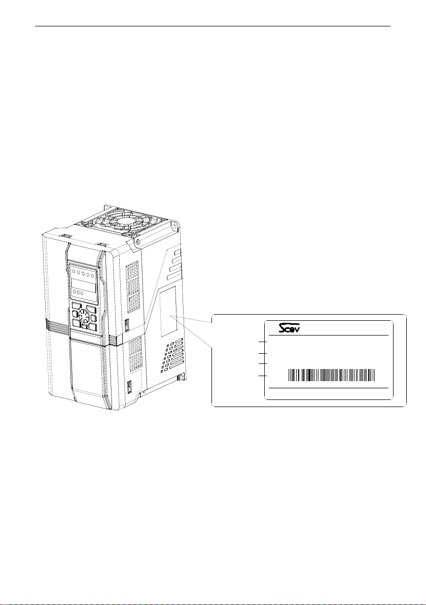
2.1.1 Nameplate explanation
When the products arrive:
Please check the appearance to confirm whether there are any scratches or dirt on the
inverter. Damage caused during product transportation is not covered by our warranty. In case
of damage to the product during transportation, please contact the shipping company
immediately.
Please confirm whether the model of the inverter is consistent with the ordered product.
You can refer to the “MODEL” column on the nameplate which on the side of the inverter
Nameplate:
Fig. 2-1 Nameplate
MODEL :
INPUT :
OUTPUT :
S/N:
Shenzhen SCOV Electric Technologes Co.,Ltd.
SV800-7R54G/114PB
3PH AC 400V 50/60HZ
7.5/11KW 17/24A
SV800 INVERTER
Inverter model
Rated input
Rated output
Serial NO. 802518301021

2 Product Introduction SV800/SV800A User Manual
6
2.1.2 Designation Rules of SV800/SV800A models
Fig. 2-2 Description of the model
SV800/SV800A 7R5 4 G / 11 4 P B
-
Inverter Series
2
4
Code
2R2
4R0
5R5
7R5
11
15
18R5
22
30
37
45
55
2.2KW
4.0KW
5.5KW
7.5KW
11KW
15KW
18.5KW
22KW
30KW
37KW
45KW
55KW
P:Fan or Pump Type
Adapted Motor
Code
G:General Type
B:Built-in Braking Unit
Voltage Grade
AC 230V
3PH AC 480V
5
3PH AC 480V
-S
S:Single phase input
SV800/SV800A User Manual 2 Production Introduction
7
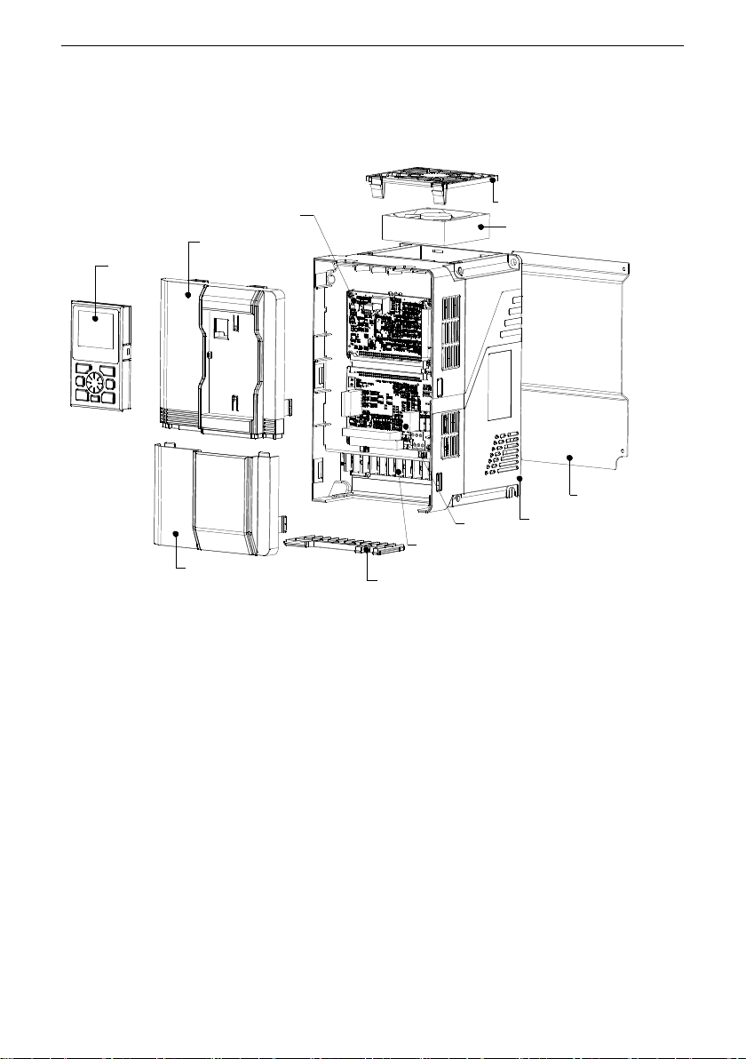
2.1.3 Components name of the frequency inverter
This section describes the components names of the inverter.
Plastic housing model
Fig. 2-3 Components names of the plastic housing model
Keyboard Upper fornt cover
Cabling board
Power terminals
TB BoardCasing
Metal bottom plate
Fan
Main control board Fan cover
Lower front cover

2 Product Introduction SV800/SV800A User Manual
8
Sheet metal housing model
Fig. 2-4 Components names of the sheet metal housing model
Shell
Fan
Fan cover
Lower front cover
Upper front cover
Keyboard
Power terminals
Keyboard
Holder

SV800/SV800A User Manual 2 Production Introduction
9
2.1.4 Product models and specifications
The model and specifications of the SV800 series are shown in below Table 2-1. The input
voltage is three-phase three-wire system (400V±15% 50/60Hz±5%), and the output voltage
varies with the input voltage; the output power PNis valid at the rated voltage UN=380V.
Table 2-1 Models and Specifications
Code
Rated load
Heavy load
High heavy
load
Carrier frequency
range
Model name
IN
A
IMax
A
PN
kW
IHd
A
PHd
kW
IHH
A
PHH
kW
Min
kHz
Max
kHz
2R24
5.5
8.3
2.2
4.0
1.5
2.4
0.75
1.0
15.0
SV800-2R24GB
4R04
10
15
4.0
5.5
2.2
4.0
1.5
1.0
15.0
SV800-4R04G/5R54PB
5R54
13
19.5
5.5
10
4.0
5.5
2.2
1.0
15.0
SV800-5R54G/7R54PB
7R54
17
25
7.5
13
5.5
10
4.0
1.0
15.0
SV800-7R54G/114PB
114
24
35
11
17
7.5
13
5.5
1.0
15.0
SV800-114G/154PB
154
32.5
48
15
24
11
17
7.5
1.0
15.0
SV800-154G/18R54PB
18r54
38
57
18.5
32.5
15
24
11
1.0
15.0
SV800-18R54G/224PB
224
46
69
22
38
18.5
32.5
15
1.0
15.0
SV800-224G/304PB
304
62.5
93
30
46
22
38
18.5
1.0
15.0
SV800-304G/374P
374
75.5
113
37
62.5
30
46
22
1.0
15.0
SV800-374G/454P
454
92.5
138
45
75.5
37
62.5
30
1.0
15.0
SV800-454G/554P
554
111
166
55
92.5
45
75.5
37
1.0
15.0
SV800-554G/754P
754
146
219
75
111
55
92.5
45
1.0
15.0
SV800-754G/904P
904
169
253
90
146
75
111
55
1.0
15.0
SV800-904G/1104P
1104
210
315
110
169
90
146
75
1.0
15.0
SV800-1104G/1324P
1324
246
369
132
210
110
169
90
1.0
15.0
SV800-1324G/1604P
1604
300
450
160
246
132
210
110
1.0
15.0
SV800-1604G/1854P
1854
350
525
185
300
160
246
132
1.0
15.0
SV800-1854G/2004P
2004
370
555
200
300
160
246
132
1.0
15.0
SV800-2004G/2204P
2204
415
623
220
350
185
300
160
1.0
15.0
SV800-2204G/2504P
2504
460
690
250
370
200
300
160
1.0
15.0
SV800-2504G/2804P

2 Product Introduction SV800/SV800A User Manual
10
Code
Rated load
Heavy load
High heavy
load
Carrier frequency
range
Model name
IN
A
IMax
A
PN
kW
IHd
A
PHd
kW
IHH
A
PHH
kW
Min
kHz
Max
kHz
2804
510
765
280
415
220
350
185
1.0
15.0
SV800-2804G/3154P
3154
600
900
315
460
250
370
200
1.0
15.0
SV800-3154G/3554P
3554
660
990
355
510
280
460
250
1.0
15.0
SV800-3554G/4004P
4004
740
1110
400
600
315
460
250
1.0
15.0
SV800-4004G/4504P
4504
820
1230
450
660
355
600
315
1.0
15.0
SV800-4504G/5004P
5004
920
1380
500
740
400
660
355
1.0
15.0
SV800-5004G/5604P
5604
990
1485
560
820
450
740
400
1.0
15.0
SV800-5604G/6304P
6304
1160
1665
600
920
500
740
400
1.0
15.0
SV800-6304G
7504
1380
2070
750
1160
630
920
500
1.0
15.0
SV800-7504G
10004
1840
2760
1000
1380
750
1160
630
1.0
15.0
SV800-10004G
Note: <1>Under vector control, the frequency inverter can drive motors with the power are three to four
times smaller than the inverter power. Standard V/F control does not have this limitation.
<2> The carrier frequency range means that the control algorithm can operate stably under the maximum
carrier frequency, but the motor needs to be de-rated when the carrier frequency is larger than the factory
default value.
2.1.5 Heavy load application and de-rating use of frequency inverter
For rated load application:
The motor is allowed to output a maximum of 1.5 times of the rated torque; INin Table 2-1 is
the rated current that can be used continuously when the inverter is not overloaded; PNis the
typical motor power adapted when there is no overload; IMax is the maximum overload current
allowed by the inverter, allowing continuous operation for 1 minute / 5 minutes at 40 ℃.
For heavy load application:
The inverter should be derating used by one grade and the motor is allowed to output more than
1.5 times of the rated torque; IHd in Table 2-1 is the rated current of the continuously running
motor. The motor overload protection is set by P0-03 (motor overload protection setting) and
P0-04~P0-06 (motor over-torque protection); The output current of the inverter is limited by
IMax and allowed to run continuously for 1 minute / 5 minutes at 40℃; PHd is the typical motor
power adapted for heavy load applications.
For high heavy load applications:
The inverter should be de-rating used by two grades and the motor allows output greater than
twice times of the rated torque; In table 2-1, IHH is the rated current of the continuously running
motor. The motor overload protection is set by P0-03 (motor overload protection setting) and

SV800/SV800A User Manual 2 Production Introduction
11
P0-04~P0-06 (motor over-torque protection); The output current of the inverter is also limited
by IMax, allowing continuous operation for 1 minute / 5 minutes at 40 ℃; PHH is the typical
motor power adapted for high heavy load applications.
Fig.2-5 Overload protection diagram
Overload protection:
Both the inverter and the motor will perform overload protection and over-torque protection.
The motor protection parameters can be set in the inverter. When the inverter output current is
1.5 times of the rated current (or IMax), it is allowed to run for 1 minute / 5 minutes at 40 ℃, as
shown in Figure 2-5.
The guidance of derating using:
When the user needs the motor to output more than 1.5 times of the rated torque, the inverter
should be derated used as described above in the heavy load application. When the ambient
temperature of the inverter, altitude and other factors changed or the carrier frequency of the
inverter is greater than the factory default value, derating using (passive) is required; In addition,
when the motor is required to run at a very low speed for a long time, the carrier frequency must
be reduced or the inverter must be derated. Derating method as shown in Table 2-2 or you can
consult the manufacturer.
Table 2-2 The guidance of inverter derating using
Derating factors
Derating guidance
Temperature
The rated value of the inverter is measured at 40 °C. If the ambient temperature rises, the capacity should
be reduced by 3%/1 °C and the maximum ambient temperature is 50 °C.
Altitude
After the altitude is higher than 1000 meters, derating 1% for each 100 meters.
Carrier
frequency
When the carrier frequency of the inverter is higher than the factory default value, in principle, the inverter
should be derated used by one grade or consult the manufacturer directly.
Current or oL%
t/min
1.5IN
1.05IN
1 2 3 4 5
oL%=100%
Overload counting curve
Current amplitude

2 Product Introduction SV800/SV800A User Manual
12
Derating factors
Derating guidance
When it needs to run at very low speed with rated output, please consult the manufacturer or derating use
the inverter by one grade.
Note: The factors affecting the output capability of the inverter are not limited to the above factors, if any
questions, please consult the manufacturer or supplier.
Table of contents
Other SCOV Inverter manuals


