Mac Afric MGENER-220 User manual

Gasoline Generating Sets
I
Operator
Manual
MGENER-220
MGENER-221
MGENER-450
MGENER-550

Thank you for purchasing our generator.
We
want to help you get the best results from your new generator and to operate it safely. This
manual contains the information
on
how
to
do that; please read it carefully.
This owner's manual describes the operation and maintenance of the Generator. All information
in
this pubilcation is based
on
the latest
product information available
at
the time of printing.
we
reserve the right to make changes at any time without notice and without incurring any
obligation. No part of this publication may be reproduced without written permisson.
This manual should be considered a permanent part of the generator and should remain. with it if it'is resold.
Safety Messages ·
Your
safety and the safety of others
is
very important.
We
have provided important safety messages
in
this manual and
on
the generator.Please
read these messages carefully.
A safety message alerts you to potential hazards that could hurt you or others. Each safety message
is
preceded
by
a safety alert symbol
filand
one of three words: DANGER, WARNING, or CAUTION.
These mean
f!'lJ•Vmij::lij
You
Will
be KILLED
or
SERIOUSLY HURT
if
you.
don't
follow
instructions.
f!'\!l!M;l@[#J You CAN be KILLED
or
SERIOUSLY HURT
if
you
don't
follow
instructions.
F!'t!f•mm@J
You CAN be HURT
if
you
don't
follow
instructions.
Each message tells you what the hazard
is.
what can happen, and what you can do to avoid or reduce injury.
Damage
Prevention
Messages
You
will also see other important messages that are preceded by.the word NOTICE.
This word means:
I NOTICE I Your
generator
or
other
property
could
be
damaged
it
you
don't
follow
instructions.
The purpose of these messages
is
to help prevent damage to your generator, other property, or the environment.

CONTENTS
SAFETY.......................................................................................................................................................................................4
Safety Label Location...............................................................................................................................................................4
Safety lnformation....................................................................................................................................................................5
COMPONENT IDENTIFCATION..................................................................................................................................................7
CONTROLS.................................................................................................................................................................................9
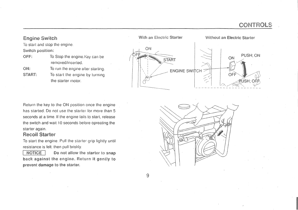
Engine Switch..........................................................................................................................................................................9
Recofl Starter...........................................................................................................................................................................9
Fuel Valve...............................................................................................................................................................................i O
Choke Rod.............................................................................................................................................................................
10
Circuit Breaker........................................................................................................................................................................
11
Grand Terminal ......................................................................................................................................................................
11
Oil Alert System.....:................................................................................................................................................................
11
Pilot Lamp..............................................................................................................................................................................12
DC
Termina.ls...........................................................................................................................................................................12
DC
Circuit Protector...............................................................................................................................................................12
GENERATOR USE.....................................................................................................................................................................
i 3
Connections to a Building's Electrical System.........................................................................................................................13
Generator Ground Circuit.......................................................................................................................................................
13
AC
Applications.......................................................................................................................................................................14
AC
Operation..........................................................................................................................................................................i 5
DC
Operation..........................................................................................................................................................................16
Disconnecting the battery cables............................................................................................................................................17
PREOPERATION CHECK.........................................................................................................................................................18
Engine Oil.................................................................................................................................................................................18
Fuel Recommendation..............................................................................................................................................................19
STARTING THE ENGlNE............................................................................................................................................................
21
STOPPING THE ENGINE...........................................................................................................................................................22 I
2
i
I

MAINTENANCE............................................................................................................................................................................
23
Maintenance Schedule...........................................................................................................................................................23
Engine Oil
Air Cleaner
Fuel Sediment Cup
Spark Plug Service..............................................................................................................................................................27
TRANSPORTING/STORl\GE....................................................................................................................................................29
TROUBLESHOOTING................................................................ .............................................................................................
31
SPECIFICATIONS.....................................................................................................................................................................33
SPECIFICATIONS.....................................................................................................................................................................35
Generator set electric wiring diagram................... .......................................................................................................37
Operation
3

SAFETY
SAFETY
LABEL
LOCATION
These labels warn you of potential hazards that can cause serious injury. Read them carefully.
If
a label comes off or becomes hard
to
read, contact your generator dealer for a replacement.
CD
.
CV
CD
Q)
CTl
AC
DC
VOLTAGE VOLTAGE 12V
FREQUENCY
60Hz
CURRE~IT
BA
RATED
OUTPUT
...
kw
MAX
OUTPUT
...
kw FUEL GASOLINE
PHASE 1 (PETRPL)
..
Do
not connect to a building's electrical system unless
an
isolation switch has been installed by a qualified
electrician.
• Using a generator or
an
electrical appliance
in
wet conditions such
as
rain or snow or near a pool or sprinkler
system, or when your hands are wet, could result
in
electrocution. Keep the generator
dry.
4
I
I

SAFETY INFORMATION
Generators are designed to give safe and dependable service if operated according
to
instructions. Read and understand this owner's manual
before operating your gernerator.
You
can help prevent accidents
by
being familiar with your generator's controls and
by
observing safe operating
procedures.
Operator
Responsibility
• Know how to stop the generator quickly
in
case of emergency. (See Page 22)
e Understand the use of all generator controls, output receptacles and connections.
• Be sure that anyone who operates the generator receives proper instruction.
Do
not let children operate the generator.
Carbon
Monoxide
Hazards
• Exhaust contains poisonous carbon monoxide, a colorless and odorless gas. Breathing exhaust can cause loss of consciousness and may
lead
to
death.
$
If
you run the generator
in
an area that is confined, or even partially enclosed, the air you breathe could contain a dangerous amounts of
exhaust gas.
To
keep exhaust gas from building
up,
provide adequate ventilation.
Electric
Shock
Hazards
• The generator produces enough electric power to cause a serious shock or electrocution if misused.
• Using a generator or electrical appliance
in
wet conditions, such as rain or snow, or near a pool or sprinkler system, or when your hands are
wet, could result
in
electrocution. Keep the generator dry.
•
If
the generator
is
stored outdoors, unprotected from the weather, check all electrical components
on
the control panel, before each use.Moisture
or ice can cause a malfunction or short circuit
in
electrical components which could result
in
electrocution.
•
Do
not connect
to
a building's electrical system unless
an
isolation switch that has been installed by a qualified electrician.
5 I
I
I
~
r

Fire and
Bum
Hazards
• The exhaust system gets hot enough
to
ignite some materials.
-Keep the generator at least 1 meter (31eet) away from buildings and other equipment during operation.
-
Do
not enclose the generator
in
any structure.
-Keep flammable materials away from the generator.
• The muffler becomes very hot during operation and remains hot for a while after stopping the engine. Be careful not
to
touch the muffler while
it
is
hot. Let the engine cool before storing the generator indoors.
• Gasoline is extremely flammable and
is
explosive under certain conditions.
Do
not smoke or allow flames or sparks where the generator is
refueled or where gasoline
is
stored. Refuel
in
a well-ventilated area with the engine stopped.
• Fuel vapors are extremely flammable and may ignite after the engine has started. Make sure that any spilled fuel has been wiped up before
starting the generator.
6

CHOKE ROD VOLTfVIETEFi ELECTRICAL OUTLET
FUEL VALVE
GROUND
TERfVllN/>,L
AIR
CLEANER
CIRCUIT BREAl<ER
ENGINE ON/OFF SWITCH SERIAL NO.
7

FUEL TANK CAP FUEL METER
MUFFLER
SPARK PLUG
CAP
Record the engine number for your future reference. (See Page
7)
Refer
to
this serail number when ordering parts, and when making technical
requests.
Engine serial number:
-------------------~
8

Switch
To
star! and stop the engine.
Switch
posl!ivn:
OFF:
To
Stop the engineJ\ey can be
removed/inserted.
ON:
STt~RT:
To
run the engine after starting.
To
start the engine by turning
the starter motor.
Return the key to the
ON
position once the engine
has started.
Do
not use the starter for more than 5
seconds at a time. II
the
engine rails
to
start, release
the switch and wait 1
Oseconds before opreating the
starter again.
Recoil Starter
To
start the engine Pull the starter grip lightly until
resistance
is
felt. then pull briskly.
I NOTICE I Do
no!
ailDw
!he
start&r
tc1
snap
back
against
the
engine.
Ret~m1
ii
gently
to
prevent
damage
to
the
starter.
CONTROLS
'\NlUmut an Electric
Siar!er
9

Fuel Valve
The fuel valve
is
located between
ihe
fuel
tank and carburetor. When the valve lever
is
in
the ON position, fuel
is
allowed to flow
from the fuel tank to the carburetor.
Be
sure
to
return the lever to OFF after stopping the
engine.
Choke Rod
The choke
is
used
to
provide
an
emiched
fuel
mixture when cold starting.
The
choke
can
be
opened
by
moving the choke
rod
to
the right
and closed
by
moving the choke rod
to
the
left.
10

Circuit Breaker
The circuit breaker will automatically switch OFF if there
is
a short circuit
or
a
significant overload of the generator at the receptacle.
If
the circuit breaker
is
switched OFF automatically, check that the applicance
is
working properly
and does not exceed the rated load capacity of the circuit before switching
the circuit breaker
ON
again.
Ground Terminal
The generator ground terminal
is
connected to the frame of the generator,
on
a metal non-current carrying parts
of
the generator,
and
the ground terminals
of
each receptacle.
circuit breaker
_,,
DC
circuit protertor
+
@ 0 0
+ -
Oil
Alert
System
DC
12
Ground terminal
The Oil Alert system
is
designed
to
prevent engine damage caused
by
an
insufficient amount of oil
in
the crankcase. Before the oil level
in
the
crankcase can fall below a sale limit, the Oil Alert system will automatically shut down the engine (the engine switch will remain
in
the
ON
position). The 1500&1300 do not have this feature.
11

Pilot Lamp
The pilot lamp
is
illuminated when the generator
is
operating normally.
DC
Terminals
The
DC
terminals may
ONLY
be used for charging
12
volt automotive type batteries.
The terminals are colored
red
to identify the positive(+) terminal and black
to
identify the negative(-) terminal. The battery must
be
connected
to the generator
DC
terminals with the proper polarity (battery positive to generator red terminal and battery negative
to
the generator black
terminal.)
DC
Circuit
Protector
The
DC
circuit protector automatically shuts off the
DC
battery charging circuit when the generator
is
overloaded, when there
is
a problem with
the battery or the connections between the battery
and
the generator are improper.
DC
circuit protector
© Ground terminal
circuit breaker
0
+
DC
12
12

GENERATOR USE
Connections
to
a
Building's
Electrical
"'"'"'*'"'""1'
Connections for standby power
to
a building's electrical system must be made
by
a qualified electrician. The connection must isolate the
generator power from utility power, and must comply with all applicable laws and electrical codes.
F'!'\W•j;l~llWil
Improper
connections
to
a
building's
electrical
system
can
allow
electrical
current
from
the
generator
to
backteeci
into
the
lltility
lines.
Such
bacldeed may
electrocute
utility
company
'Jll"r~(ers
or
othern
who
contact
the
lines
during
a
power
ou!age.
Consult
lhe
utility
company
or
a
qualified
electrician.
F1'tli£\ffi@Rl
Improper
connections
to
a
bliilding's
electrical
sys~em
can
allow
electrical curren1
Imm
the
utility
company
io
bacldeeci
into
the
generator.When
utility
power
is
restored,
the
generator
may
explode,
bum,
or
cause
!ires
in
the
building's
electrical system.
In
some areas, generators are required by law to be registered with local utility companies. Check local regulations for proper registration and
use procedures.
Generator
Ground
Circuits
Portable generators have a system ground that connects the generator frame components
to
the ground terminals
in
the
AC
ouiput receptacles.
The system ground
is
not connected to the
AC
neutral wire.
Local regulations, codes or laws may require that the ground system be connected to the
AC
neutral wire. If the generator
is
tested
by
a
receptacle tester,
it
will not show the same ground circuit condition
as
for a home receptacle.
II
local regulations, codes, or laws require the system ground to be connected
to
the
AC
neutral wire, consult a qualified electrical or electrical
inspector.Provide him with the electrical wiring diagram
in
this manual.
The ground terminal can
be
used
to
earth the generator or bond the rrame of the generator
to
the frame of a vehicle, but only
if it
is
required by
local law or electrical code. Before using the ground terminal consult a qualified electrican or electrical inspector for regulations
in
your area.
13

AC
Applications
Before connecting
an
appliance or power cord
to
the generator;
• Make sure that
it
is
in
good working order. Faulty appliances or power cords
can
create a potential for electrical shock.
• If
an
appliance begins
to
operate abnormally, becomes sluggish or stops suddenly, turn
it
off immediately. Disconnect the applicance, and
determine whether the problem
is
the appliance, or if the rated load capacity ol the generator has been exceeded.
• Make sure that the electrical rating ol the tool or appliance does not exceed that of the generator, Never exceed the maximum power rating of
the generator. Power levels between rated and maximum may be used for
no
more than 5 minutes.
I NOTICE I Substantial overloading
wm
open the
circuit
breaker. Exceeding
U1e
!ime
limit
for
maximum
power
operation
or
siigMly
overloading
the
generator
may
no!
switch
thii'
circuil
breaker
OFF,
but
will
shorten
the
service
iiie
of
the generator.
Limit operation requiring maximum power
to
5 minutes.
Maximum power is: See specifications. (Pages 33&34)
For continuous operation, do not exceed the rated power.
Rated power is: See specifications. (Pages 33&34)
In
either case, the total power requirements
(VA)
of all appliances connected must be considered. Appliance and power tool manufactures
usually_list rating information near the model number or serial number.
14

AC Operation
1.
Start the engine.
2.
Switch ON the
AC
circuit breaker. DC circuit protector
Ground terminal
0
circuit breaker + •
DC12
3.
Plug
in
the appliance.
Most motorized appliances require more than their rated wattage for startup.
Do
not exceed the current limit specified for any one receptacle.
If
an
overloaded circuit causes the
AC
circuit breaker to swith
OFF,
reduce the
electrical load on the circuit, wait a few minutes and then reset the circuit-breaker.
15

DC operation
The DC terminals may ONLY be used for charging 12 volt automotive-type batteries.
Connecting the battery cables:
i.
Before connecting charging cables to a battery that is installed
in
a vehicle, disconnect the vehicle's grounded battery cable.
f!'\wZiornl!Mij
The battery gives
olf
explosive gases; keep sparks, flames and cigarettes away. Provide adequate ventilation when
charging
or
using
batteries.
2.
Connect the
positive(+)
battery cable to the battery
positive(+)
terminal.
3.
Connect
the
other
end of the
positive(+)
battery cable to the generator
positive(+)
terminal.
(~c
,;,~:C:j~~
-~
circuit
breaker
/
Ground
terminal
j
DC 12
4. Connect the
negative(-)
battery cable to the battery
negative(-)
terminal.
5.
Connect the
other
end of the
negative(-)
battery cable to the generator
negative(-)
terminal.
6.
Start the
rnerator.
I NOTICE
Do
not
start the vehicle while the battery charging
cables
are connected and the generator
is
n.mning.The vehicle
or
the
generator may be damaged.
An overloaded DC circuit, excessive current draw by the battery,
or
wiring problem will trip the DC circuit protector (PUSH button extends out).
II
this happens,
wait
a few minutes
before
pushing
in the circuit
protector
to resume operation. II
the
circuit
protector
continues
to go OFF,
discontinue charging and see your authorized generator dealer.
16
I
I
I

1 Stop the engine.
2.
Disconnect the negative(-) battery cable from the generator negatvie (-)terminal.
3.
Disconnect the other end of the negative(-) battery cable from the battery negative(-) terminal.
4.
Disconnect the positive(+) battery cable from the generator positive(-:-) terminal.
5.
Disconnect the other end of the positive(+) battery cable
to
the battery positive(+) terminal.
6.
Connect the vehicle ground cable to the battery negative(-) terminal.
7.
Reconnect the vehicle grounded battery cable.
DC
circuit protector
Ground terminal
circuit breaker
DCl2
17

PRE-OPERATION CHECK
Engine oil
I NOTICE I Engine oil is a
major
factor
affecting engine perfor-
mamce and
service
me.
Non-de1<>rgen~
and 2-str00ke
engine
oils
will
lllanage
the engirne and are
not
rec:timmended.
Check the
o,;
level BEFORE EACH USE with the generator on a level
surface with the engine stopped.
Use 4-stroke oil, or
an
equivalet high detergent, premium quality
rK'or
oil certified to meet or exceed
U.S.
automobile manufacturer's requir-
ements for Service Classification SG, SF/CC,
CD.
Motor oils classified
SG, SF/CC, CD will show this designation
on
the container.
(1) SG.SF/CC.CD SINGLE VISCOSITY
(2) SG.SF/CC.CD MULTI VISCOSITY
SAE 1
OW-30
is
recommended for general, all-temperature use. Other
viscosities shown
in
the chart may
be
used when the average tempera-
ture
in
your area
is
within the indicated range.
1.
Remove the oil filler cap and wipe the dipstick clean.
2.
Check the oil level
by
inserting the dipstick into the filler neck without
screwing it in.
3.
If the level
is
low,
fill
to
the top of the oil filler neck with the recomm-
ended oil.
18
SAE
Viscosily
Grades
..
-
~30
..
&..
lOW-30
..
..
-~
~sW-30
-
~
'"1
-20
O
20
40 60
80
100° F
-30 -20 -10
0
10
20
30 40'C
AMB
I
ENT
TEIVIPERATURE

Fuel Recorn1mtmdation
1.
Check. the fuel level gauge.
if
ihe
fuel level is low. Do not lill above the
shoulder
of the fuel strainer.
urn::ler
certain
conditions.
•
R:efruel
!n
are,a
wiU1
!he
enqine
s~')P!le1:L
Do
11ot
::;rr1oke
or
allow
flames
i-eto.iel"d
or
where
gasoline
is,
stored.
.,
De;
no!
overi'ill the fuel tank
sl101Jlci
be Ii
lier
when
wiih
skin
m·
br,eatMng
ol
CMILDREM.
See specifications. (Pages 33&34)
FUEL
TANK
CAP
FUEL
LEVEL
GAUGE
Use gasoline with a
pump
octane
rating
of
86 or higher.
We
recommend
unleaded gasoline
because
it
produces
levver
engine
and
spark
f\Jever
use stale
or
contaminated gasoline
or
oil/gasoline mixture. Avoid getting
th'.~
tan!'
cap is closed
is
spi~!ed,
sum
FUEL
STRAl!\JER
deposit
and extends exhaust
sysiem
life.
or water
in
the fuel tank.
This manual suits for next models
3
Table of contents
Other Mac Afric Inverter manuals
Popular Inverter manuals by other brands

Hopewind
Hopewind hopeSunHV Series user manual

BorMann
BorMann KUMATSUGEN GB1500 owner's manual

PulseTech
PulseTech SP-25 User and installation manual

Tsun
Tsun SOL-RSDM-DD Quick installation guide

Northern Lights
Northern Lights OM3-80 Operator's manual

Plasma Air
Plasma Air 200 SERIES Installation, operation & maintenance manual

Trannergy
Trannergy PVI 5400TL user manual

AEG
AEG Protect PV 2800 operating instructions

Yamaha
Yamaha EF2000iSv2 manual

Dometic
Dometic PERFECTPOWER PP604 Installation and operating manual

Power Electronics
Power Electronics SD 500 Series Hardware and installation manual

Lenze
Lenze i950 Series Commissioning manual