1
I
N
A
U
S
T
R
A
L
I
A
P
R
O
U
D
L
Y
B
U
I
L
T
Continued Over.../
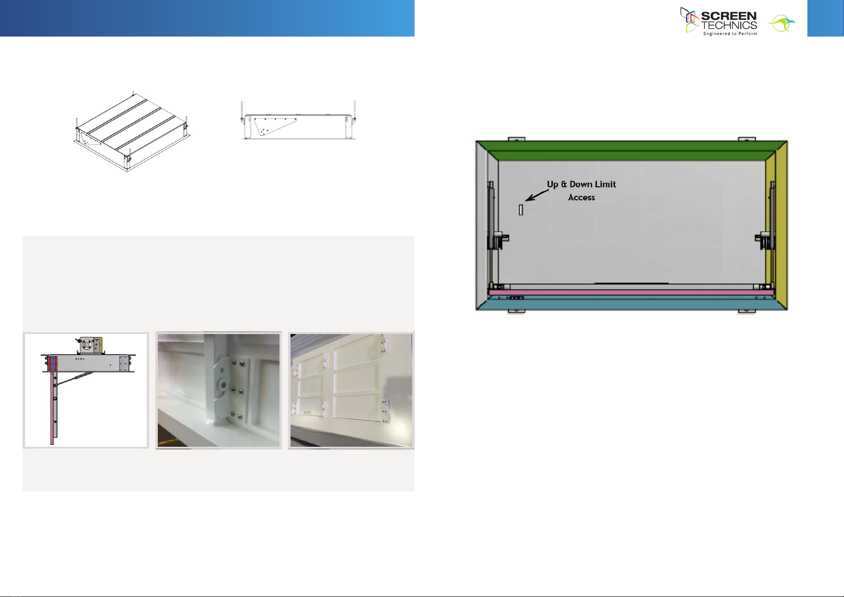
INSTRUCTIONS - SWING DOWN FLAT PANEL LIFT
Thank you for purchasing a Screen Technics Swing Down Flat Panel
Lift, please ensure that you read the following instructions fully before
attempting to install this product.
NOTE: THIS SWING UTILISES AN ADVANCED FALL ARRESTOR SYSTEM, THE SWING DOWN CAN ONLY BE OPERATED
IN A HORIZONTAL POSITION, IF THE SWING DOWN IS OPERATED ON ITS SIDE OR NOT IN A HORIZONTAL POSITION,
THE ANTI-FALL DEVICE WILL LOCK AND DISCONNECT POWER. IF THE ANTI-FALL DEVICE IS ACTIVATED, IT WILL
REQUIRE REPLACEMENT.
1. CONTROL
• Supplied with a Connect motor controller
• Infra-Red operation
• 2 x Dry Contact close inputs Up/Down
2. 4 CORE WIRING WAGO CONNECTOR
• Pin 1 – Brown Down
• Pin 2 – Black Up
• Pin 3 – Yellow / Green Earth
• Pin 4 – Blue Neutral
3. INSTALLATION EXAMPLES
• Bolted to timber in ceiling, attached to ceiling structure
1. Control.
a. Supplied with a Connect motor controller
b. Infra-Red operation
c. 2 x Dry Contact close inputs Up/Down
2. 4 Core Wiring Wago Connector
a. Pin 1 – Brown Down
b. Pin 2 – Black Up
c. Pin 3 – Yellow / Green Earth
d. Pin 4 – Blue Neutral
3. Installation Examples
a. Bolted to timber in ceiling, attached to ceiling structure
b. Attached to cable or chain to a
suitable structure within ceiling
space, using adjustable shackles
for levelling
c. Utilising 4 angle brackets, and mount using threaded rod
• Attached to cable or chain to a suitable structure within ceiling space, using adjustable
shackles for levelling
info@screentechnics.com.au
screentechnics.com.au
AUSTRALIA
22-24 Suttor Road, Moss Vale NSW 2577
+61 2 4869 2100
NEW ZEALAND
44 Mahana Road, Te Rapa, Hamilton
0800 022 821
I
N
A
U
S
T
R
A
L
I
A
P
R
O
U
D
L
Y
B
U
I
L
T