2
I
N
A
U
S
T
R
A
L
I
A
P
R
O
U
D
L
Y
B
U
I
L
T
Continued Over.../
INSTRUCTIONS - INTERFIT PROJECTOR LIFT – FVI and HTI Series
ALL-THREAD BROOKER ROD
STEP 1. Secure 4 x brooker rods to a suitable overhead
structure with a proprietary loxin system designed to
accept threaded rod.
STEP 2. Space around the outside corner dimensions of
the unit.
STEP 3. Wind a set of nuts up the rods above the installation height and then insert the rods
through the supplied angle brackets, now attached to the lifter unit.
STEP 4. Now wind on a set of nuts under the bracket till the ceiling edge trims are rmly
pressing against the underside of the ceiling material, then wind the upper nuts down
onto the angle brackets to lock off unit.
Installations are best achieved by have access into the roof space but this is not always
possible, and in these instances we advise the following practices:
PROJECTOR INSTALLATION
STEP 1. This unit comes with a blank projector mounting
plate that requires you to mark out the mounting holes
and drill where appropriate.
STEP 2. Removal of the plate for drilling and tting is
achieved by undoing the 2 off Allen key bolts along the
front underside edge of the mounting plate, and pulling
the plate forward.
STEP 3. These 2 off Allen key bolts will later be the adjustment method used for yaw or side to
side alignment of the projector, with the threaded adjustment winder used for pitch or up and
down adjustment of projector.
STEP 4. For ease of adjustment and cable tting the ceiling plate can be removed from
the projector shroud assembly by undoing the 6 x Allen key bolts that surround
the ceiling plate from the outside perimeter of the shroud, as below.
INSTALLING FROM BENEATH THE CEILING LINE
STEP 1. Connect power in a safe manner to the unit and support the lifter so you can motor the
projector cage lower than the ceiling edge trims and you will see 6 Allen key bolts holding the
cage assembly to the unit. Remove these and set aside the cage unit.
STEP 2. Remove the projector mounting plate by removing the 2 Allen key bolts at the front
under side of plate and pull the forward to remove from the lifter assembly.
STEP 3. Motor the remaining assembly to the full up position (watch out for your ngers…) and
you now have room to access the interior of the unit.
STEP 4. Inspect the 8 installation slots running up the corner frame uprights. These are used to
secure the device to some suitable structure from below the ceiling line.
STEP 5. Either add some timber in the ceiling along two sides to coach bolt into place or suspend
from threaded rod or some suitable angle brackets.
STEP 6. Raise the unit into the ceiling, t the screws or bolts (as appropriate to selected method)
and apply upward pressure to the unit so the ceiling edge trims are pressed rmly against the
underside of the ceiling material and tighten off the screws or bolts.
STEP 7. Motor down the mechanism and ret the projector plate and cage assembly.
PLEASE NOTE: When utilising the above method of installation from beneath the ceiling, it is best
to use a method of xing to any structure that will allow you at a latter date to remove the lifter
for any future servicing issues, without the need to break into the ceiling – please consider this
issue before deciding on the best installation method.
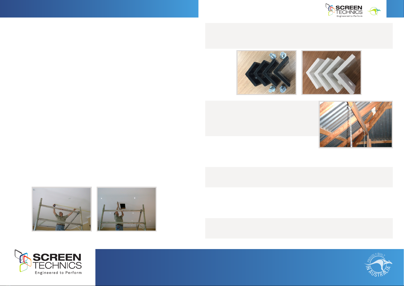
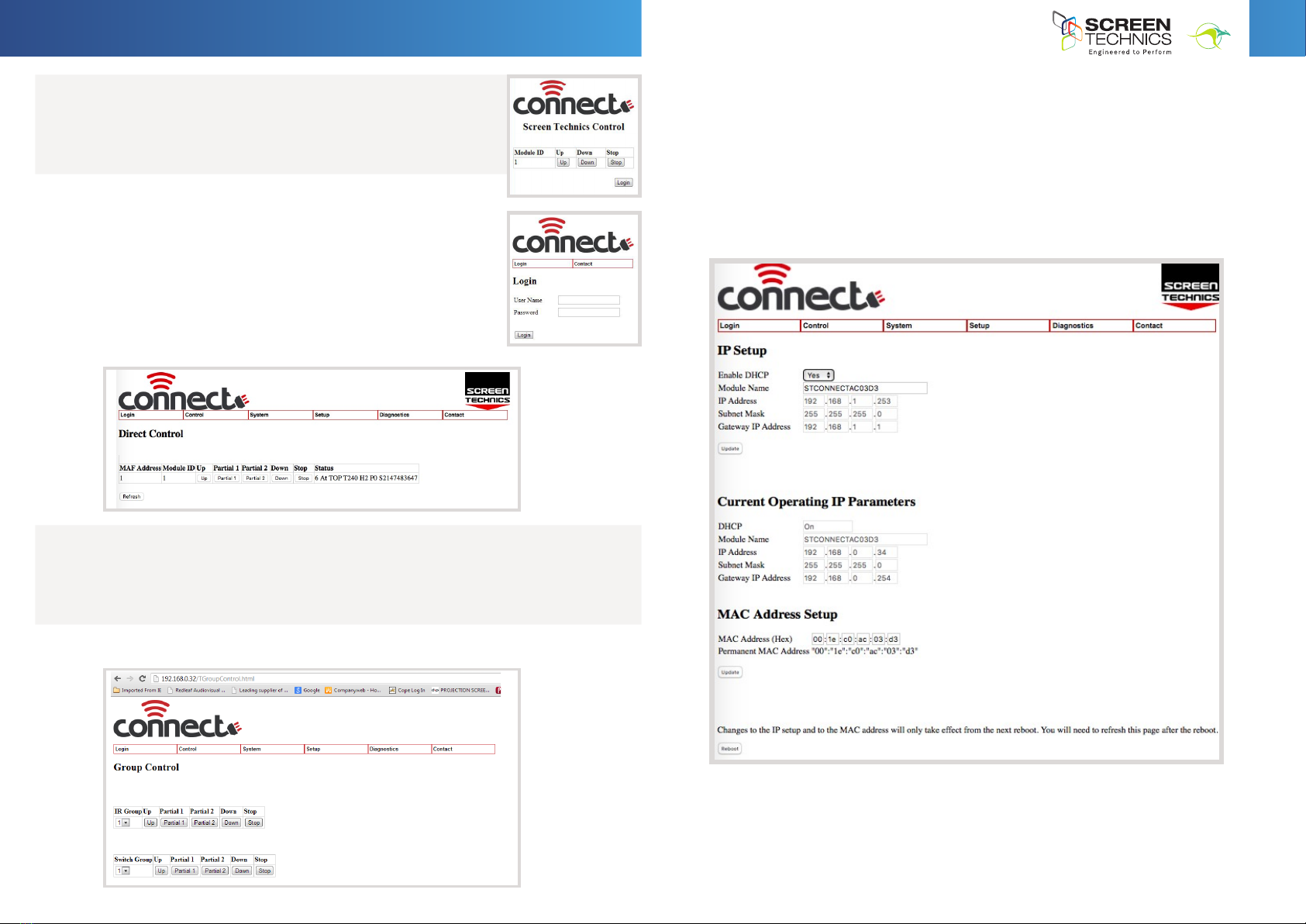
Chain and Turnbuckle
Secure the chain to a suitable structure, such as overhead timber beams, or dyna-bolted to an overhead
concrete slab.
A minimum of 4 points to secure the chain is required and it is the installers
responsibility to ensure the chain turnbuckle system chosen is strong enough for
the safe installation of the unit.
Now raise the unit into the ceiling, hold in position from below while a second
person secures the other end of the chain to the lifter using the supplied BLACK
angle brackets and tighten the turnbuckles till the units ceiling edge trims are
firmly pressing against the underside of the ceiling material.
Lock off the turnbuckles.
All-thread Brooker Rod
Secure 4 x brooker rods to a suitable overhead structure with a proprietary loxin
system designed to accept threaded rod.
Space around the outside corner dimensions of the unit.
Wind a set of nuts up the rods above the installation height and then insert the rods
through the supplied angle brackets, now attached to the lifter unit.
Now wind on a set of nuts under the bracket till the ceiling edge trims are firmly
pressing against the underside of the ceiling material, then wind the upper nuts down
onto the angle brackets to lock off unit.
Installations are best achieved by have access into the roof space but this is not always possible, and in these
instances we advise the following practices:
Installing from Beneath the Ceiling Line
Connect power in a safe manner to the unit and support the lifter so you can motor the projector cage
lower than the ceiling edge trims and you will see 6 Allen key bolts holding the cage assembly to the unit.
Remove these and set aside the cage unit.
Remove the projector mounting plate by removing the 2 Allen key bolts at the front under side of plate
and pull the forward to remove from the lifter assembly.
Motor the remaining assembly to the full up position (watch out for your fingers…) and you now have room
to access the interior of the unit.
Inspect the 8 installation slots running up the corner frame uprights. These are used to secure the device
to some suitable structure from below the ceiling line.
Either add some timber in the ceiling along two sides to coach bolt into place or suspend from threaded
rod or some suitable angle brackets.
Raise the unit into the ceiling, fit the screws or bolts (as appropriate to selected method) and apply
upward pressure to the unit so the ceiling edge trims are pressed firmly against the underside of the
ceiling material and tighten off the screws or bolts.
Motor down the mechanism and refit the projector plate and cage assembly.
Please Note: When utilising the above method of installation from beneath the ceiling, it is best to use a method of
fixing to any structure that will allow you at a latter date to remove the lifter for any future servicing issues, without
the need to break into the ceiling – please consider this issue before deciding on the best installation method.
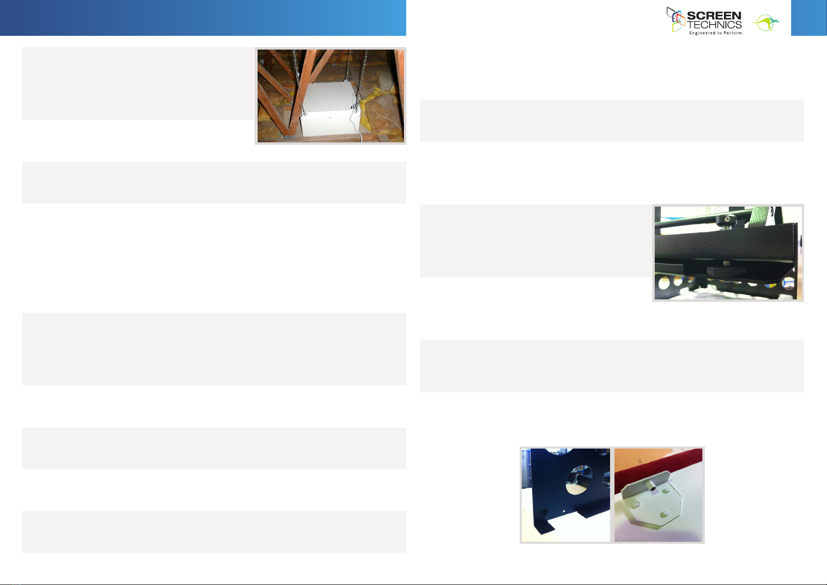
Projector Installation
This unit comes with a blank projector mounting plate that requires you to mark
out the mounting holes and drill where appropriate.
Removal of the plate for drilling and fitting is achieved by undoing the 2 off
Allen key bolts along the front underside edge of the mounting plate, and
pulling the plate forward.
These 2 off Allen key bolts will later be the adjustment method used for yaw or
side to side alignment of the projector, with the threaded adjustment winder
used for pitch or up and down adjustment of projector.
For ease of adjustment and cable fitting the ceiling plate can be removed from
the projector shroud assembly by undoing the 6 x Allen key bolts that surround
the ceiling plate from the outside perimeter of the shroud, as below.
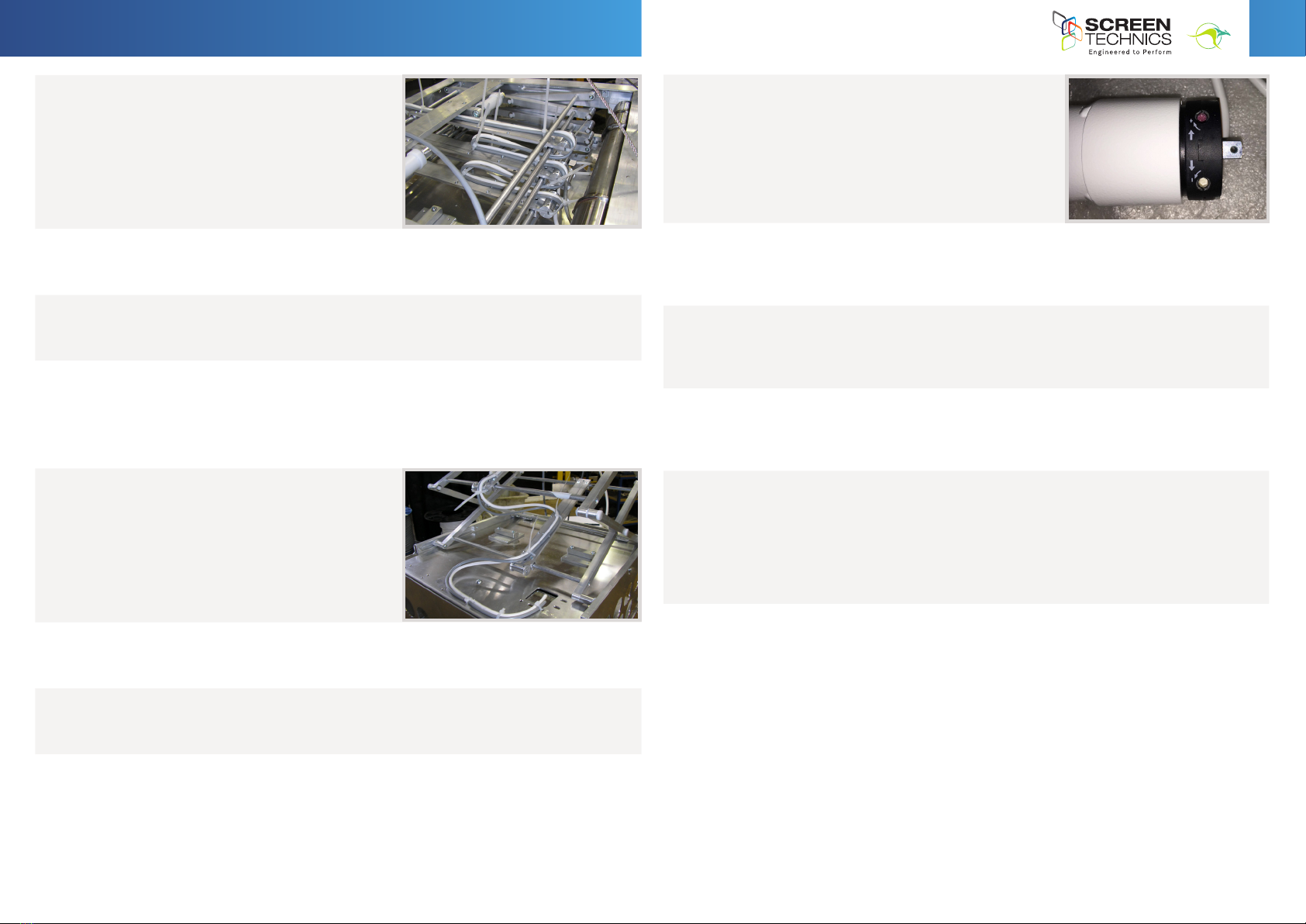
Cable Management for Units with 200mm to 600mm Travel
The rear of the projector mounting plate has a cable management access hole that
allows you to run cables through and into the cable management channel.
Lay out the required cables and lock them into position utilising cable ties in the
small regular holes running up the channel.
Be sure to allow enough slack in the cables at every hinged elbow point so the
cables don’t interfere with the travel of the lifter.
Exit cables through the supplied opening on top of the unit.
Cable Management for Units over 600mm Travel
On units with longer travel a second type of cable management is required.
Above the projector mounting position is an access hole for the cables and various
cable tie mounting holes, please see the picture below this text.
This allows the cables to run up the centrally mounted cable run planes, to the
mid section of the plane, where the cable tie holes cease.
This is the point where you stop and run to the front of the upper cable run plane,
leaving enough slack in the installation for so cables don’t pinch or stretch.
Projector Installation
This unit comes with a blank projector mounting plate that requires you to mark
out the mounting holes and drill where appropriate.
Removal of the plate for drilling and fitting is achieved by undoing the 2 off
Allen key bolts along the front underside edge of the mounting plate, and
pulling the plate forward.
These 2 off Allen key bolts will later be the adjustment method used for yaw or
side to side alignment of the projector, with the threaded adjustment winder
used for pitch or up and down adjustment of projector.
For ease of adjustment and cable fitting the ceiling plate can be removed from
the projector shroud assembly by undoing the 6 x Allen key bolts that surround
the ceiling plate from the outside perimeter of the shroud, as below.
Cable Management for Units with 200mm to 600mm Travel
The rear of the projector mounting plate has a cable management access hole that
allows you to run cables through and into the cable management channel.
Lay out the required cables and lock them into position utilising cable ties in the
small regular holes running up the channel.
Be sure to allow enough slack in the cables at every hinged elbow point so the
cables don’t interfere with the travel of the lifter.
Exit cables through the supplied opening on top of the unit.
Cable Management for Units over 600mm Travel
On units with longer travel a second type of cable management is required.
Above the projector mounting position is an access hole for the cables and various
cable tie mounting holes, please see the picture below this text.
This allows the cables to run up the centrally mounted cable run planes, to the
mid section of the plane, where the cable tie holes cease.
This is the point where you stop and run to the front of the upper cable run plane,
leaving enough slack in the installation for so cables don’t pinch or stretch.