Sapphire Audio SETC200WSF-ATR User manual

Instruction M anual for
Recessed-Ceiling Screen

114
(1) F or adjusting the viewing area, please insert the adjustment to regulate adjustment hole. A
clockwise adjustment will increase the viewing area for about 13mm.
Note: After pressing the up button, you will need a few seconds to see the adjustment of screen;
and after pressing the down button, you will see the position changed of screen.
Please do not operate the following s tep before s tep1 to avoid damages of screen.
(2) A counterclockwise cycle can adjust the distance to 13mm between casing and rod.
Please be careful while operating, too much retracting will cause the damages of screen and motor.
Caution
by inappropriate installation or operation.
2. Please keep the screen away from hot sources, such as radiator, heating machine, fireplace,
loudspeaker or other relative device.
3. Only Plug with ground wire is acceptable.
4. Only accessories from authorized supplier is acceptable.
5. Please unplug the power wire when lighting and raining or not use with a long time.
6. Please contact the professional for installation and repairing .
7. Please prevent screen from wet and water .
8. As soon as the plug of the screen is connected to the power source, the screen is connecting
with electricity .
9. Please use the approved power line (three-core power line)/ device interface/power plug.
10. Please use the rating (voltage, amps) power line (three-core power line) / device interface/power
plug. If have any questions about power line/ device interface/power plug, please contact the
professional people.
11. After installation, please locate a power device in order to disconnect power or connect the power
plug to electrical socket. This electrical socket should be installed to a convenient position. If the
accident occurs during operation, please disconnect power or take out the power plug.
12. The ceiling or wall used for fixture installation must be secure enough; load-bearing requirement
must be 4 times of the screen to prevent the screens from falling.
13. Before using, please remove the fixation strap and screws from the low bar to avoid the damage of product.
1. Please read carefully with this instructions before installation to avoid damage to product causing
Warnings : Please prevent screen from wet place to avoid electric or fire dangerous.
Warnings
To prevent from electric
dangerous, please don't
remove the end cap. There
is no need for users to
check the parts inside,
please handle the problems
to professional repairman.
Please notice the non-insulated voltage of the
spare parts to prevent from electric dangerous.
Please operate according to the user manual
with the screen.
Note:
1. Due to product updates, sizes and specifications are subject to change at any time.
The tolerance for L is approximately ± 5mm (3/16 inches).
2. Actual dimension is measured by: total screen length L x end cap depth x end cap height.
B1
B2
H
W
AB3
L
B1 B2 B3
2037x1146
2347x1320
2657x1494
2656
2966
3276
SE TC200W SF- ATR
SE TC240W SF- ATR
SE TC270W SF- ATR
92
106
120
80
80
80
65
65
65
400
400
400
Product Specifications

13
三. Screen Adjustment
(Please take apart the baffle when adjusting the screen. And please reinstall the baffle after adjusting.)
Please be careful while operating, too much retracting will cause the damages of screen and motor.
E. S ynchro Power Relay(optional)
After connecting the Wireless Synchro
Converter, the screen can be controlled
by FM modulation wireless controller
which can cooperate with Sychro Power
Relay and switch of projector to control
the up and down of screen synchronously.
D. E xternal Wall S witch (optional)
The wall switch is available for a fixed location. Please
connect RJ11 plug to EXTCTR L input on the screen.
Note: please use a cord for a far location. Wall Switch
(optional)
Screen R etracting Adjustment
R eference:
(Note: This a djustment is not safety, please contact the professional people for repairing and avoid damaging of
screen and warranty failure)
C aution we strongly recommend that do not regulate the s creen limitation privately. The s tandard limitation of
screen is s et from the factory and this s tandard can satisfy the requirement of users.
“ ”
“ ”
2
Screen Fabric
Aluminum C asing
Low Bar
M12 Nut (12pcs)
M12 Bar (4pcs)
M12 B ar
M12 Nut
Hook
Bracket
Front View
Hook (4pcs) Pressing P iece (2pcs)
Wrench (1pc)
M10X 100 E xpansion
Screw (8pcs)
Hanging B oard (2pcs) M6 Allen Screw (4pcs) M6 Nut (4pcs) M5 S crew (4pcs)
Instruction Manual (1pc)
Infrared R emote C ontroller (1pc)
External Infrared R eceiver (1pc) Trigger Line ( 1pc)
Sychro Power Relay and
Wireless S ynchro Converter
IR to R F receiver
Power Synchro
and IR
Side Vi ew
P ower line
Description
Accessaries

3
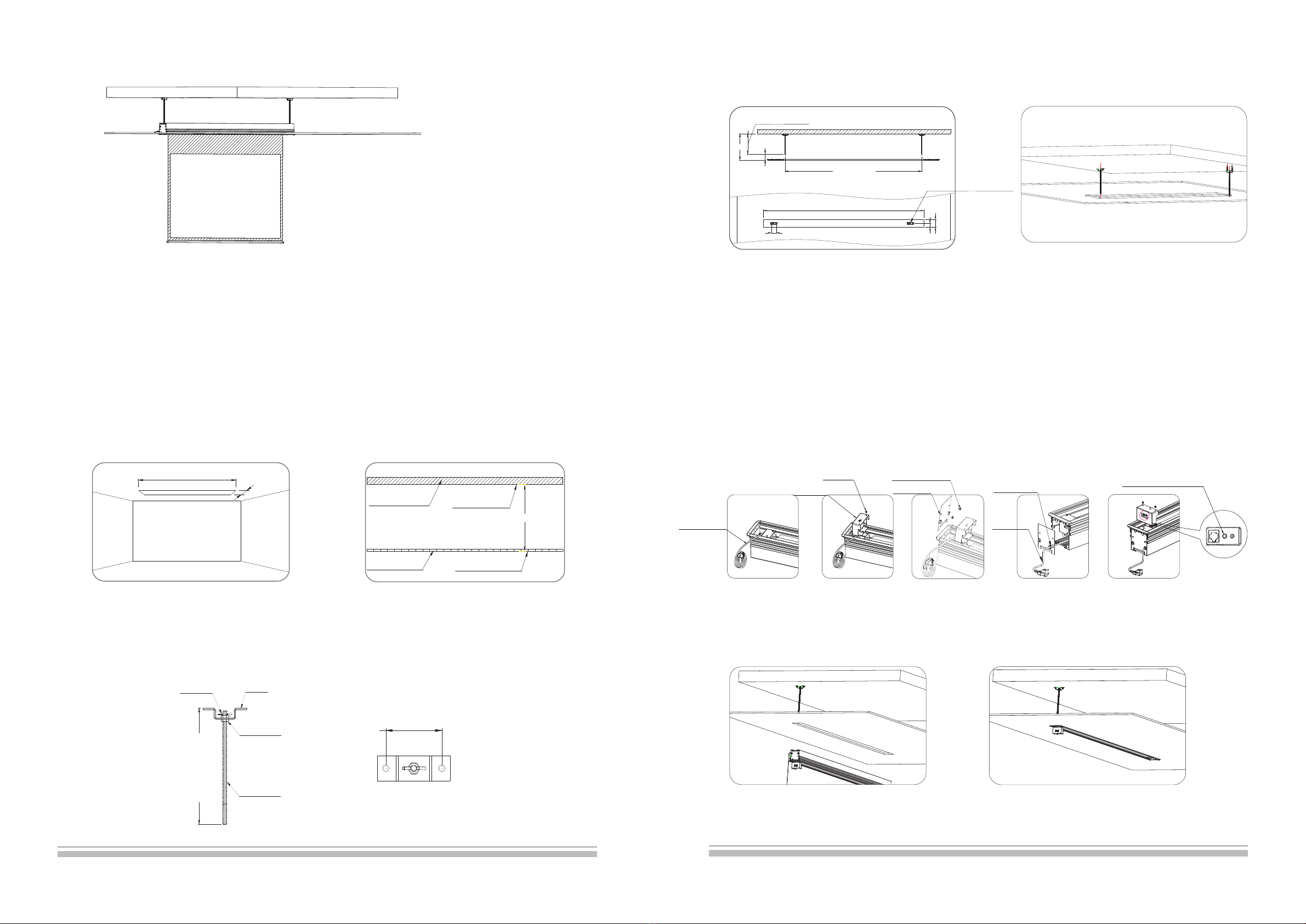
1.C hoose a position according to the required space, and then take apart the ceiling (figure 1). P lease measure the
distance H between concrete roof and ceiling s urface correctly (figure 2 ).
一. G rille-Ceiling Mount
Take apart the ceiling
Figure 2
C oncrete R oof R oof Surface
C eiling S urface
G rille-ceiling
Figure 1
H
2.This s creen equips bracket, and build up the hanging bracket using the hook, M 12 nut and M12 bar. C ut the length
of M12 bar to H minus 1 00mm(H is the distance between concrete roof and ceiling s urface) (Note: H is 5 00mm, the
length of hanging bracket is 4 00m which is 5 00mm minus 1 00mm) (figure 3).
figure 3
C eiling
C oncrete R oof
Low Bar
L minus 2 6mm
( )The width of groove
L( )The length of screen
M12 B ar
Screen
Screen Fabric
Hook
100
Hanging B oard
This number of bars c an
be four and two according
to different installation.
158( )The width of groove
170( )The length of screen
12
Caution
1.The shortest distance between receiver and emitter is 50cm。
2.Controller will work within 30 degree away horizontally from the center
of receiver point within 8 meters from the screen。
3.The controller will not work if the signal is covered by somthing。
4.Keep the controller far away from high temperature and humid situation。
5.Please change the battery when the signal is weak。
6.Please take the battery out if the controller was not being used for long
time 。
Controller Battery Installation
1.Turn the controller around,push to open the cover as guide arrow.
2.Put the battery in according to the guide of cathode anode 。
3.Close the cover。
二. External Control System
Four control systems are available
for motorized screen
(1)Manual C ontrol
(2)Infrared R emote C ontrol (IR )
(3)Dry C ontact
(4)Switch
EXT CTRL
TRIG
EXT IR
Trigger
Dry C ontact/R S232
External Infrared R eceiver
B. Infrared R emote C ontrol:
B ecause of the recessed mount, the
external infrared E X T lr input must be in
serted by external infrared receiver, then
please fix it in eyes for control.
External Infrared Input
A.Manual C ontrol:
The manual control button is under
power box:
(C lose to power line)Cyclic C ontrol
C yclic C ontrol
Up
Stop
Down
Stop
C . Trigger :
1. P lease connect 2,5mm plug of trigger to
the TR IG i nput on the s creen; connect 3.5mm
plug to the output on trigger (only for the e quip
ments which have trigger function)
2. The projection screen will automatically
lower when the projector is on. It will automatically
retract when the projector is turned off
Trigger Line
Projector
TRIGGER
This s creen needs to be recessed into the ceiling, and this instruction manual shows us the grille-ceiling and
wood-ceiling as e xample. P lease install the s creen according to different applications. This s creen needs to be
recessed at the best viewing angle in order to improve the image. Take out all the parts from the packaging and
follow the accessories g uideline to ensure you have all parts.
M12 B ar
M12 Nut
Hook
Brooch
H 100mmminus
100. 0
Mz2 S crew (4pcs)
Approximately
150mm
Installation Instruction
Back View

4
3.Please measure the s ecurity distance between hanging brackets ( figure 4 ), and fix the hanging brackets on the
ceiling using expansion screws ( figure 5).
4, P lease follow the below steps to install the power cord which recessing in casing, and plug in the e xternal infrared receiver
(because of the recessed mount, the external infrared receiver must be ready for control).
1)Take out the power cord (figure 6).
2)Loose the s crews of power box and take out the power box ( note: the power box must be buttoned on the hanger of bracket
according to figure 11, please put up and move back the power box to take out), because the power cord has a limit, please do
not draw it strongly.
3)Loose a nd take out two rubber screws, then remove the end cap (figure 8-9).
4)R emove the line cover of end cap, then fill in the power line. Afterward, s tuck the line cover back to end cap, then install the
power line outside the casing.
5)Install the end cap again (figure 10)
6)Insert the e xternal infrared receiver to EX T IR h ole (figure 10) (note: please put the completed external infrared receiver into
inside frame of screen to avoid the pressing from screen). Then install the power box back to bracket (note: ensure the power
box is buttoned on the hanger of bracket) (figure 11).
figure 4 figure 5
TRIG( )Trigger
EXT IR( )
External
Infrared Receiver
EX T C TR L(
)
Dry
C ontact/R S 232
Figure 10
Signal Output
Switch
M4 S crew
Note: the power box must be
buttoned on the hanger of bracket.
Bracket
Power Box
End C ap Board
Figure 11
Four Hanging
Boards are in middle.
100
H
L 94minus
H 100minus
180
100
Figure6
Power Line
Figure7 Figure8 Figure9
11
C ontroller Buttons F unction Instruction
1.Press button ,screen goes up。
2.Press button ,screen goes down。
3.Press button ,screen stops。
4.Press M icro-up button ,screen can be increased
by fine-tuning。
5.Press M icro-down button ,screen can be decreased
by fine-tuning。
LED
Up
Down
Stop
Micro-down
Micro-up
Model:1G D— IR an
Front View
Product Instruction
1.Infrared Remote Control
11. Installation C ompleted (figure 27).
Note: the upward instructions a re only suitable for the distance H which between 210-600mm; if the distance is
greater than 600mm, please follow the s teps a s below:
1)Install the hanging bracket at a required position before ceiling fitment (M12 bar is not provided) (figure 28).
2)S aw an oblong groove at a completed ceiling (note: please ensure the hanging bracket must be installed in the
middle of this g roove) (figure 29). The rest of steps can follow the instructions a s before!
Figure27
Figure29
Figure28 Two Hanging
Boards a re in middle.
L( ) 26mmTotal length of screen minus
Not completed ceiling
H 100minus
100
L 94minus
158
79
Power Box
Screw
R ubber Screw
End C ap Board
Power Line
Line C over
100

10
Note: the upward instruction shows us installation of external control system, if the users want to add other control
systems, please follow the s teps a s below:
1)Loose the s crews of power box and take out the power box (because
the power cord has a limit, please do not
draw it strongly). Then loose two rubber screws again, and remove the
end cap (please ensure the power line is
fixed), s tep 3 can be follow.
2)Insert the control system signal line to corresponding output (figure 11),
and take out the s ignal line from control
system signal line e xit (figure 19).
3)R einstall the end cap after completed control system and fasten the
two rubber screws then reinstall the power box and fasten two screws
according to step 8.
10. Install the front baffle as following s teps
1) E xtend the s creen and keep the rear baffle opening
2) D isconnect the power of screen,and then install the front baffle
3)Please ensure the s ecurity lock is unlocked (figure 2 2).
4)Install the front bafle (figure 23)
5)Unlock the s ecurity lock of baffle (figure 24、figure 25), insert the
plug of security to a hole of end cap (figure 26), if the baffle can not
move up that please align baffle with ceiling board.
6)C onnect the power after installation
Figure21
Signal Line E xit
Figure22
Figure24 Figure25 Figure26
Figure23
5.Please s tay the s creen in the opposite direction, and fix the left and right hanging board on the s creen using
M6 s crew and nut (figure 12).
6. Install the whole s creen on the hanging bracket (figure 13-14)
7. F ix the s creen using M 12 nut (figure 1 5), then adjust the s ecurity distance to H (the distance between concrete roof and ceiling
surface) using adjusting s crew. Loose the M 12 nut and fix the whole s creen, a nd then connect the power (figure 16).
5
Figure13
figure 12
Figure15
Figure14
1)
in the groove of casing.
Stay the M 6 allen screw 2) I nstall the hanging
board 3) P lease ensure the
distance between edge
of hanging board and the
edge of casing is 5 mm.
4) F asten the hanging board
using M 6 nut, and install other
hanging board at the s ame way.
Hanging B oard
C asing G roove M6 Allen Screw
M6 Nut
8. C ut the s eparated ceiling board in a s uitable s ize, which can fill in the s ize of space as s creen (figure 1 7-18).
Figure18Figure17
Figure16
5.0
Unlocked Locked
M12 S crew (4pcs)
M12 Nut
Power Line
1) Insert the baffle to top groove. 2) S tay flat the baffle,
and clip it to low groove.
3) Press the baffle slightly
and align it with ceiling board.
Top Groove
Low Groove
Ensure two faces
are the same level

9
7.Please e nsure the hexagon surface of nut and inside s urface of casing are at the s ame level (figure 16); s tay the
pressing piece on the nut (figure 17-18)
8. I nsert the external infrared receiver to EX T IR h ole(figure 18),
infrared receiver must be ready for control, then install the power box back to bracket .
(note: ensure the power box is buttoned on the hanger of bracket) (figure 19).
because of the recessed mount, the e xternal
Figure16 F igure18Figure17
Two surfaces a re
at the s ame level
Figure18
EX T C TR L
()
Dry
C ontact/R S 232
EXT IR( )
External
Infrared Receiver
TRIG( )Trigger
Figure19
Figure15
M12 S crew
Wrench
Not provided
(screwdriver
can replace)
Align the ornament
board with ceiling
Figure13 Figure14
Wrench
Bracket
Button
Note: the power box must be
buttoned on the hanger of bracket.
Power Box
Screw
6
Figure22 Figure23 Figure24
Note: the upward instruction shows us installation of external control system, if the users want to
add other control systems, please follow the s teps a s below:
1)Loose the s crews of power box and take out the power
box (because the power cord has a limit,
please do not draw it strongly). Then loose two rubber
screws again, and remove the end cap
(please e nsure the power line is fixed), s tep 3 can be follow.
2)Insert the control system signal line to corresponding
output (figure 11), and take out the s ignal
line from control system signal line exit (figure 18).
3)R einstall the end cap after completed control system
and fasten the two rubber screws then
reinstall the power box and fasten two screws according
to step 4.
Figure19
Signal Line E xit
Unlocked Locked
6. F ix the s creen using M 12 nut, then fasten the nut by wrench (accessories) (figure 13-14); until the ornament
board align the ceiling (figure 1 5) and connect the power.
Power line
M5 S crew
Pressing P iece
1) Insert the baffle to top groove. 2) S tay flat the baffle,
and clip it to low groove.
3) Press the baffle slightly
and align it with ceiling board.
Figure20
Figure21
10. Install the front baffle as following s teps
1) E xtend the s creen and keep the rear baffle opening
2) D isconnect the power of screen,and then install the front baffle
3)Please ensure the s ecurity lock is unlocked (figure 2 2).
4)Install the front bafle (figure 23)
5)Unlock the s ecurity lock of baffle (figure 24、figure 25), insert the
plug of security to a hole of end cap (figure 26), if the baffle can not
move up that please align baffle with ceiling board.
6)C onnect the power after installation
Top Groove
Low Groove
Ensure two faces
are the same level

7
二. Wood C eiling
1. S aw an oblong groove at a required position (figure 1); P lease measure the distance H between concrete roof
and ceiling s urface correctly (figure 2).
C oncrete R oof R oof Surface
C eiling S urface
Wood Ceiling
H
L( ) 26mmTotal length of screen minus
158mm
Figure1 Figure2
11. Installation C ompleted (figure 2 5).
.Note: the length of M12 bar is 5 00mm. P lease prepare the bar your self if the distance H ( between concrete roof
and ceiling) is longer than 600mm.
Figure25
8
4, P lease follow the below steps to install the power cord which recessing in casing .
1)Take out the power cord (figure 6).
2)Loose the s crews of power box and take out the power box (note: the power box must be buttoned on the hanger
of bracket according to figure 11, please put up and move back the power box to take out), because the power
cord has a l imit, please do not draw it strongly.
3)Loose and take out two rubber screws, then remove the end cap (figure 8).
4)R emove the line cover of end cap, and then fill in the power line. Afterward, s tuck the line cover back to end cap,
then install the power line outside the casing (figure 9)
5) P lease complete the installation of end cap and fasten two rubber screws; do not need to install the power box
at this moment.
5. Install the whole s creen on the hanging bracket (figure 11-12)
Figure 4 Figure 5
Figure9
Figure7 Figure8Figure6
Figure11 Figure12
3.Please measure the s ecurity distance between hanging brackets ( figure 4), and fix the hanging brackets on the
ceiling using expansion screws ( figure 5).
L( ) 26mmTotal length of scr een minus
158
100
79
H 100minus
Power Line
图10
2.This s creen equips bracket, and build up the hanging bracket using the hook, M 12 nut and M12 bar. C ut the length of M12 bar to
H minus 1 00mm(H is the distance between concrete roof and ceiling s urface) (Note: H is 5 00mm, the length of hanging bracket is
400m which is 5 00mm minus 1 00mm) ( figure 3).
Figure 3
M12 B ar
M12 nut
Hook
Brooch
H 100mmminus
100. 0
L 94minus
100
H
Power Box
Screw EX T IR
(
)
External
Infrared Receiver
Power Line
Line C over
R ubber Screw
End C ap
Four Hanging
Boards are in middle.
This manual suits for next models
2
Table of contents
Other Sapphire Audio Projector Accessories manuals