manuals.online logo
Brands
  1. Home
  2. •
  3. Brands
  4. •
  5. InFocus
  6. •
  7. Projector Accessories
  8. •
  9. InFocus SP-CEIL-006 User manual

InFocus SP-CEIL-006 User manual

Other InFocus Projector Accessories manuals

InFocus LASER PROJECTOR LP 540 Guide

InFocus

InFocus LASER PROJECTOR LP 540 Guide

InFocus LiteShow network adapter User manual

InFocus

InFocus LiteShow network adapter User manual

InFocus SP-CEIL-010 User manual

InFocus

InFocus SP-CEIL-010 User manual

InFocus SP-CEIL-008 User manual

InFocus

InFocus SP-CEIL-008 User manual

InFocus SP-CEIL-004 User manual

InFocus

InFocus SP-CEIL-004 User manual

InFocus SP-LAMP-092 Guide

InFocus

InFocus SP-LAMP-092 Guide

InFocus CEILING MOUNT LP 1000 SERIES User manual

InFocus

InFocus CEILING MOUNT LP 1000 SERIES User manual

InFocus IN2112 Guide

InFocus

InFocus IN2112 Guide

InFocus SP-CEIL-001 User manual

InFocus

InFocus SP-CEIL-001 User manual

InFocus LP790 User manual

InFocus

InFocus LP790 User manual

InFocus CableWizard SP-CW3 Quick start guide

InFocus

InFocus CableWizard SP-CW3 Quick start guide

InFocus LP630 User manual

InFocus

InFocus LP630 User manual

InFocus WT96 User manual

InFocus

InFocus WT96 User manual

InFocus RPM A-C User manual

InFocus

InFocus RPM A-C User manual

InFocus LiteShow 4 DB+ User manual

InFocus

InFocus LiteShow 4 DB+ User manual

InFocus SP-CEIL-UNIV Guide

InFocus

InFocus SP-CEIL-UNIV Guide

InFocus LITESHOW4 DB+ User manual

InFocus

InFocus LITESHOW4 DB+ User manual

InFocus LiteProLS User manual

InFocus

InFocus LiteProLS User manual

InFocus LP 650 Guide

InFocus

InFocus LP 650 Guide

InFocus SP-LAMP-090 Guide

InFocus

InFocus SP-LAMP-090 Guide

InFocus LP70+ Guide

InFocus

InFocus LP70+ Guide

InFocus SP-LAMP-080 Guide

InFocus

InFocus SP-LAMP-080 Guide

InFocus LP130 Guide

InFocus

InFocus LP130 Guide

InFocus LP 240 Operating and safety instructions

InFocus

InFocus LP 240 Operating and safety instructions

Popular Projector Accessories manuals by other brands

Optoma BX-AL133B datasheet

Optoma

Optoma BX-AL133B datasheet

PEERLESS PE 1120 Installation and assembly

PEERLESS

PEERLESS PE 1120 Installation and assembly

Osram SIRIUS HRI Series Directions for use

Osram

Osram SIRIUS HRI Series Directions for use

Presentation Switchers PS111 quick start

Presentation Switchers

Presentation Switchers PS111 quick start

Kramer VIA GO user manual

Kramer

Kramer VIA GO user manual

Yamaha PJL-112 Replacement guide

Yamaha

Yamaha PJL-112 Replacement guide

Mitsubishi Electric 236CB Features

Mitsubishi Electric

Mitsubishi Electric 236CB Features

Epson BrightLink 475Wi user guide

Epson

Epson BrightLink 475Wi user guide

Acer WP100 quick guide

Acer

Acer WP100 quick guide

Biamp Modena Hub Network administrator's guide

Biamp

Biamp Modena Hub Network administrator's guide

Panamorph DCR-S3 installation guide

Panamorph

Panamorph DCR-S3 installation guide

Exact solutions FRAME-EVO-P10 manual

Exact solutions

Exact solutions FRAME-EVO-P10 manual

i3 i3board user manual

i3

i3 i3board user manual

CHIEF VCM103S installation instructions

CHIEF

CHIEF VCM103S installation instructions

Sharp AN-PH20EZ Operation manual

Sharp

Sharp AN-PH20EZ Operation manual

PDR UPM51 product manual

PDR

PDR UPM51 product manual

CHIEF HB-43E installation instructions

CHIEF

CHIEF HB-43E installation instructions

Sony LMP-F250 operating instructions

Sony

Sony LMP-F250 operating instructions

manuals.online logo
manuals.online logoBrands
  • About & Mission
  • Contact us
  • Privacy Policy
  • Terms and Conditions

Copyright 2025 Manuals.Online. All Rights Reserved.

A
B
C
27700B S.W. Parkway Ave.
Wilsonville, Oregon 97070-9215
1-800-294-6400
SP-CEIL-006 DIGITAL PROJECTOR MOUNT
InstallationInstructions
These are the installation instructions for your Digital Projector Mount.
Included are four methods of installation. Select the method that works
best for your viewing situation. The methods are:
Fixed Height Ceiling Installation—best for short ceilings, eight (8’) or
lower
Adjustable Height Ceiling Installation—best for high ceilings, nine (9’)
feet or higher *
Wall Mount Installation—for installing the Digital Projector Mount on a
rearwall
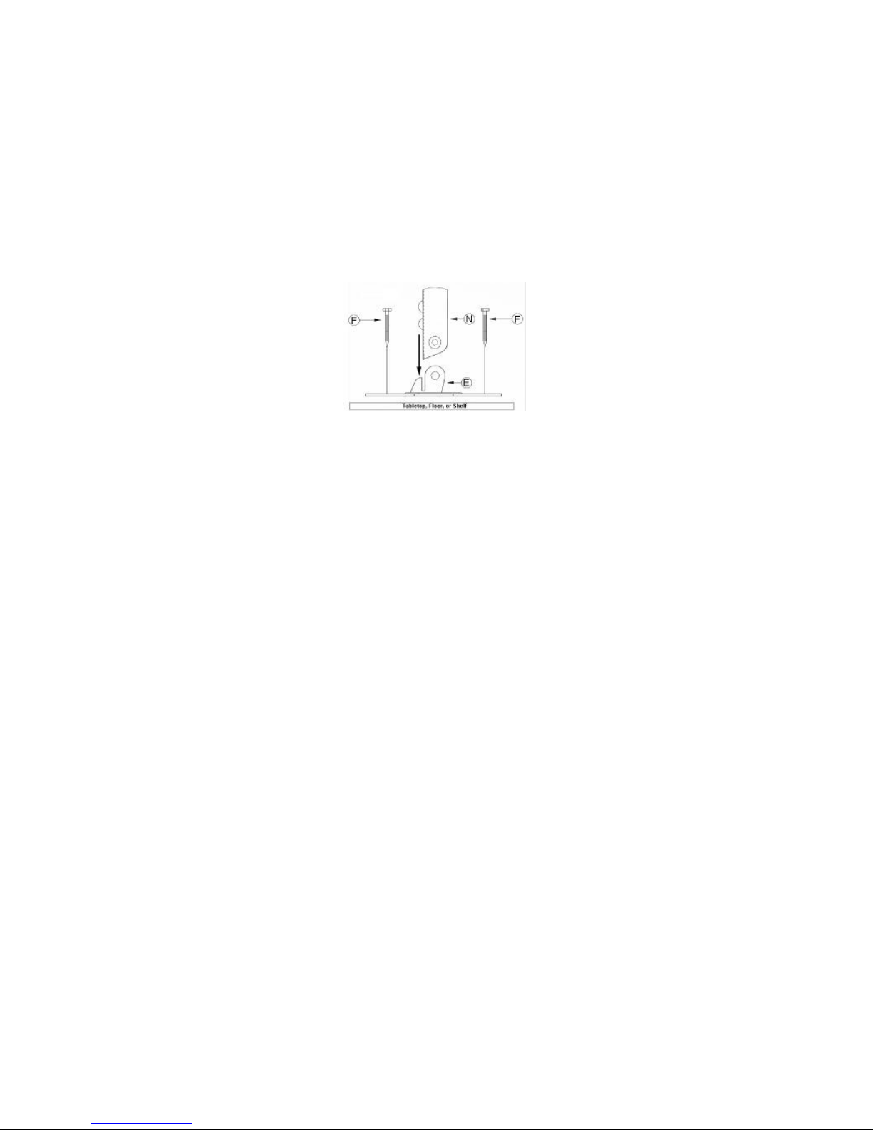
Tabletop, Shelf, or Floor Installation—for installing the Digital
Projector Mount on a tabletop, shelf, or floor
*If the required height range is greater than 12½", the optional SP-LTMT-
EXTP could be used to extend the length of the suspension adapter (see
(N) under “Hardware Description” on the next page). For further
information or ordering assistance, please contact us at the phone
number and address listed at the top of this column.
Before You Start the Installation
The wall, ceiling, tabletop, shelf, or floor where you want to install the
digital projector must be capable of supporting a weight that is five (5)
times the weight of the projector you are installing. Consult the projector’s
documentation for weight specifications. If the wall, ceiling, tabletop, shelf,
or floor is not strong enough to handle five (5) times the weight of the
projector, then you must reinforce the installation environment. If you are
unsure about theinstallation environment, please consider having it
reinforced and having the projector installed by qualified personnel.
Failure to do so could result in serious personal injury and damage to the
projector.
Copyrightby InFocus Corporation
Wilson
ville, OR. All rights reserved
•To avoid personal injury, use only an approved projector mount. Using
an unauthorized projector mount may lead to poor ventilation and
projector failure.
•When installing the projector mount, keep in mind that the projector’s
focus ring is not squarely in the center of the front of the projector, but
offset by several inches. Make sure that when you mount the projector
you offset the installation to match the amount of inches that the
projector’s focus ring is offset from thecenter of the front of the
projector.
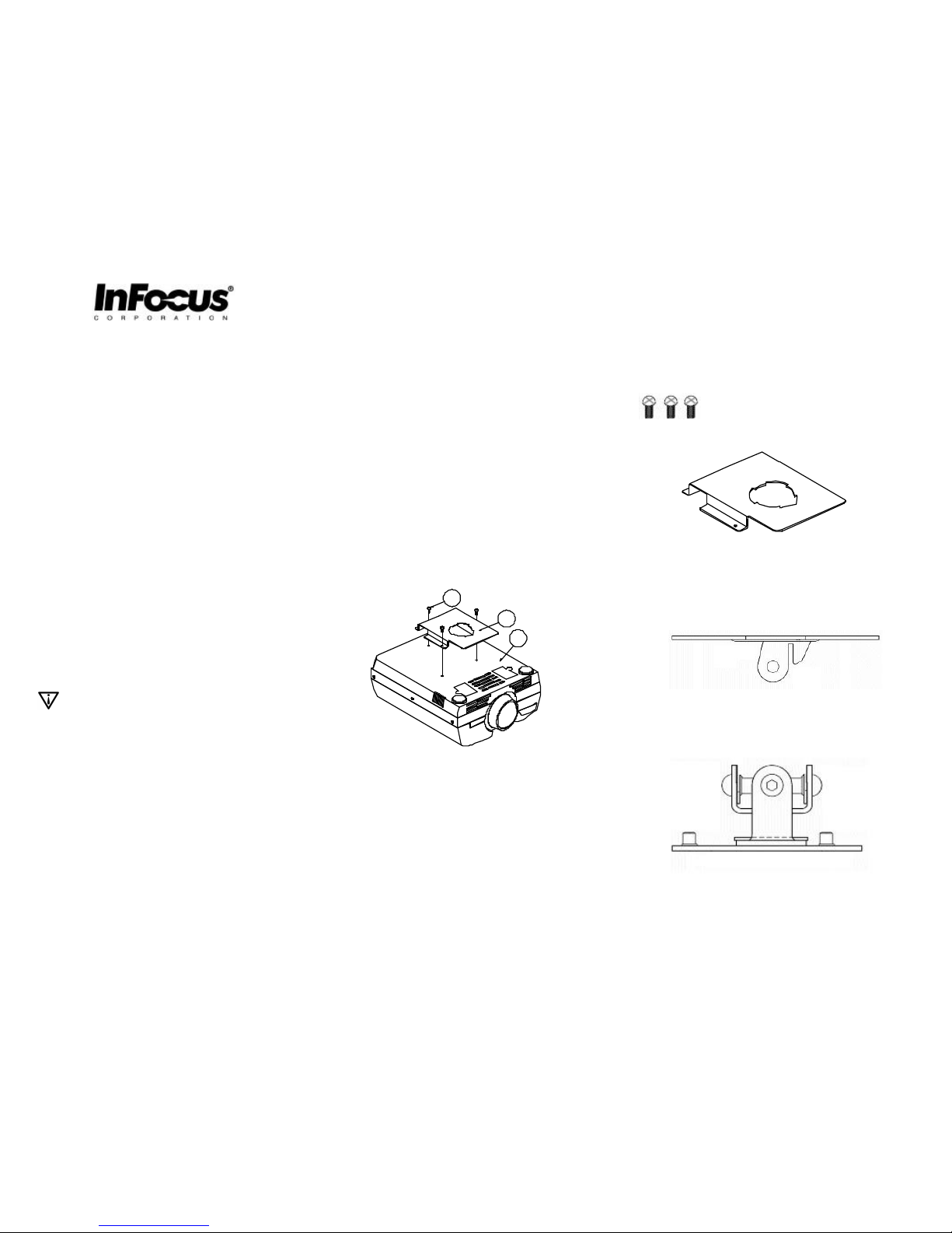
Getting the Digital Projector Ready
Before you start the installation process, prepare your Digital Projector by
performing the following steps
(FIGURE 1).
1. Turn the projector (C) upside down and place it on a clean flat
surface, preferably on a towel.
2. Locate the mounting bracket (B) and align it over the holes on the
projector.
3. Locate the three (3) 4 (mm) x 16 (mm) Phillips head screws (A).
4. Use the Phillips head screwdriver to secure the mounting bracket
(B) to the projector via the three (3) Phillips head screws (A).Do
not over-tighten the screws.
Figure 1
Tools Needed for Installing the Digital Projector Mount
You need the following tools to install the Digital Projector Mount:
•Phillips head screwdriver (not included)
•Allenwrench(included)
•Drill (for installation environment only -donot use a drill on the Digital
Projector or the Digital Projector Mount) and drill bit to match the
hardware for your installation environment (not included)
•Thecommercially available hardware (F) that is required by your
installation environment (not included)
Projected Image Sizes
For image sizes based upon the projector’s distance to the screen,
consult the ”Projected Image Size” section in your projector’s User’s
Guide.
Hardware Description
The Digital Projector Mount utilizes the following hardware. Note that the
letters associated with the hardware on this list correspond to the letters
listed in the instructions for each installation method.
(A) Three (3) 4 (mm) x 16 (mm) Phillips head screws
(B) One (1) mounting bracket
(C) Digital Projector (not included
(D) Ceiling structure (not included)
(E) One (1) upper plate
(F) Four (4) commercially available hardware anchors for the installation
environment (not included)**
(G) One (1) swivel bracket (unit-attached)
(H)One (1)safety screw
(I) One rotation plate unit attached
(J) Two (2) tension screws
(K) Two (2) height adjustable screws
(L) Single wood stud (not included)
(M) Wall structure
(N)One (1)suspension adapter
(O) One (1) Litemount Plusassembly (this contains (E), (G), and (I)
** Hardware item (F) is what secures the Digital Projector Mount to your
ceiling, wall, tabletop, shelf or floor. Make sure you consult with your
local hardware store staff for the type of hardware that works best for
your installation environment.
Fixed Height Ceiling Installation
Complete the following steps to install the projector mount and projector
onyourceiling. This installation works best with low ceilings (FIGURE 2).
Note: Look at the bottom of the swivel bracket (G) and locate the arrow.
Make sure you install the projector mount with the arrow pointing toward
your screen.
1. Secure the upper plate (E) to the ceiling (D) using the commercially
available hardware (F) suitable for your environment. Be sure that
the swivel bracket (G) arrow is pointing toward your screen.
2. Carefully raise the projector (C) with the mounting bracket (B)
attached and insert it intothe bottom of the swivel bracket (G) by its
tabs.
3. Rotate the projector (C) with the mounting bracket (B)attached
180º so that the projector’s focus ring is pointing toward your
screen.
4. Align the safety screw (H) on the swivel bracket (G) with the end of
the arrow-shaped slot on the mounting bracket (B)and screwit
through the opening to prevent further rotation. Hand-tighten the
screw(H).
5. Hand-tighten the remaining two clamp screws (J) to secure the
mounting bracket (B) to the swivel bracket (G).
Check all of the hardware for proper tightness and security. Do not over-
tighten the screws.
Figure 2
Adjustable Height Ceiling Installation
Complete the following steps to install the projector mount and projector
on your ceiling with the suspension adapter (N). This installation works
bestwith highceilings (FIGURE 3).
Note: Look at the bottom of the swivel bracket (G) and locate the arrow.
Make sure you install the projector mount with the arrow pointing toward
your screen.
6. UsetheAllen wrench to remove the upper plate (E) from the swivel
bracket (G).
7. Use the Allen wrench to remove the two screws from the enclosed
end of the of the suspension adapter (N), and place it (N) into the
slotted extension on the upper plate (E). Make sure that the two (2)
outer holes on the suspension adapter (N) align with the holes on
the slotted extension on the upper plate (E).
8. Screw the two screws removed in step 2 into the two (2) holes to
secure the suspension adapter (N) to the upper plate (E).
9. Attach the swivel bracket (G) to the suspension adapter (N) and
secure them with the two screws removed in step 1.
10. Secure the upper plate (E) to the ceiling (D) using the commercially
available hardware (F) suitable for your environment. Be sure that
the swivel bracket (G) arrow is pointing toward your screen.
11. Carefully raise the projector (C) with the mounting bracket (B)
attached and insert it into the bottom of the swivel bracket (G) by its
tabs.
12. Rotate the projector (C) with the mounting bracket (B)attached
180ºso that the projector’s focus ring is pointing toward your
screen.
13. Align the safety screw (H) on the swivel bracket (G) with the end of
the arrow-shaped slot on the mounting bracket (B)and screwit
through the opening to prevent further rotation. Hand-tighten the
screw(H).
14. Hand-tighten the remaining two clamp screws (J) to secure the
mounting bracket (B) to the swivel bracket (G).
Check all of the hardware for proper tightness and security. Do not over-
tighten the screws.
FIGURE 3
Wall Mount Installation
Complete the following steps to install the projector mount and projector
to your wall. (FIGURE 4)
Note: Look at the bottom of the swivel bracket (G) and locate the arrow.
Make sure you install the projectormount with the arrow pointing toward
your screen.
15. Use the Allen wrench to remove the upper plate (E) from the swivel
bracket (G).
16. Use the Allen wrench to remove the two screws from the enclosed
end of the of the suspension adapter (N), and place it (N) into the
slotted extension on the upper plate (E). Make sure that the two (2)
outer holes on the suspension adapter (N) align with the holes on
the slotted extension on the upper plate (E).
17. Screw the two screws removed in step 2 into the two (2) holes to
secure the suspension adapter (N) to the upper plate (E).
18. Attach the swivel bracket (G) to the suspension adapter (N)and
secure them with two screws removed in step 1.
19. Secure the upper plate (E) to the wall (M) using the commercially
available hardware (F) suitable for your environment. Be sure that
the swivel bracket (G) arrow is pointing toward your screen.
20. Carefully raise the projector (C) with the mounting bracket (B)
attached and insert it into the bottom of the swivel bracket (G) by its
tabs.
21. Rotate the projector (C) with the mounting bracket (B)attached
180º so that the projector’s focus rings is pointing toward your
screen.
22. Align the safety screw (H) on the swivel bracket (G) with the end of
the arrow-shaped slot on the mounting bracket (B)andscrew it
through the opening to prevent further rotation. Hand-tighten the
screw(H).
23. Hand-tighten the remaining two clamp screws (J) to secure the
mounting bracket (B) to the swivel bracket (G).
Check all of the hardware for proper tightness and security.Do not over-
tighten the screws.
FIGURE 4
Tabletop, Shelf, or Floor Installation
Complete the following steps to install the projector mount and projector
on a tabletop, shelf, or floor (FIGURE 5).
Note: Look at the bottom of the swivel bracket (G) and locate the arrow.
Make sure you install the projector mount with the arrow pointing toward
your screen.
24. Use the Allen wrench to remove the upper plate (E) from the swivel
bracket (G).
25. Use the Allen wrench to remove the two screws from the enclosed
end of the of the suspension adapter (N), and place it (N) into the
slotted extension on the upper plate (E). Make sure that the two (2)
outer holes on the suspension adapter (N) align with the holes on
the slotted extension on the upper plate (E).
26. Screw the two screws removed in step 2 into the two (2) holes to
secure the suspension adapter (N) to the upper plate (E).
27. Attach the swivel bracket (G) to the suspension adapter (N)and
secure them with two screws removed instep 1.
28. Secure the upper plate (E) to the tabletop, shelf, or floor (M)using
the commercially available hardware (F)suitable foryour
environment. Be sure that the swivel bracket (G) arrow is pointing
toward your screen.
29. Carefully lower the projector (C) with the mounting bracket (B)
attached and insert it into the bottom of the swivel bracket (G) by its
tabs.
30. Rotate the projector (C) with the mounting bracket (B)attached
180º so that the projector’s focus ring is pointing toward your
screen.
31. Align thesafety screw (H) on the swivel bracket (G) with the end of
the arrow-shaped slot on the mounting bracket (B)and screwit
through the opening to prevent further rotation. Hand-tighten the
screw(H).
32. Hand-tighten the remaining two clamp screws (J) to secure the
mounting bracket (B) to the swivel bracket (G).
Check all of the hardware for proper tightness and security.Do not over-
tighten the screws.
Figure 5
Figure5