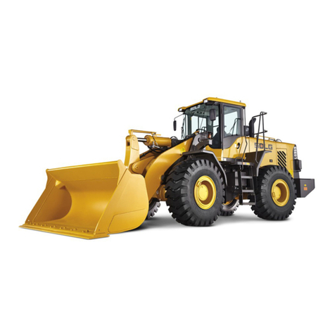
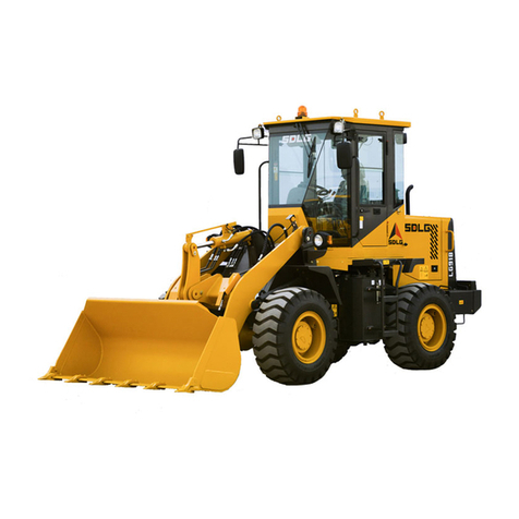
SDLG LG6210E User manual

LG6210E
Maintenance Manual
山东临工工程机械有限公司
Shandong Lingong Construction Machinery Co, Ltd

Maintenance Manual──LG6210E Hydraulic Excavator
II
Forward
This maintenance manual includes the
specifications, function information of systems and
units, maintenance instructions, checking and
adjustment methods, schematic diagrams and wiring
diagrams.
Safety
Please refer to "Safety” for safety notes for
maintenance operation on the machine.
Overall
Description I
Please refer to
Operation and Maintenance
Manual for safety problems in operating the
machine.
Maintenance
II
The operating steps are based on the special
purpose tools, E-tools and standard tools available in
the market.
The schematic diagram for E-tool can be found in this
manual.
All the lifting devices such as the belt, sling, and
ratchet wheel shell must confirm to the appropriate
national regulations regarding such devices.
If any lifting device, tool or operating method beyond
the descriptions of this manual is adopted, our
company will not be in such responsibility.
The information and data given in this manual were
valid at time of publication.
We reserve the right to make changes to the
specifications and equipment without prior notice.
Engine
III
Power
Transmission
IV
Braking
System V
Steering
System VI
Frame and
track device VII
Cab and
Interior Trim VIII
Hydraulic
System,
Working
Hydraulic
Pressure and
Other
Equipment
IX
Electrical and
Information
System X

Service Manual──LG6210E Hydraulic Excavator
I
PREFACE...............................................................................................................................................................I
SECURITY.............................................................................................................................................................1
Common precaution...................................................................................................................................1
Security precautions................................................................................................................................................. 1
Safety Devices ......................................................................................................................................................... 1
Clothing and Personal Protective Items.................................................................................................................... 1
Emergency matters preparation............................................................................................................................... 2
Fire Prevention for Oil and Fuel................................................................................................................................ 2
Properly dispose of scrap liquid................................................................................................................................ 2
Working in the dusty environmental ......................................................................................................................... 3
Preparation............................................................................................................................................................... 3
Reasonably and safely use of tools.......................................................................................................................... 4
Security locking system............................................................................................................................................ 4
.Use handrails or ladders.......................................................................................................................................... 5
Precautions when operating .........................................................................................................................5
Maintain the cooling system safety........................................................................................................................... 5
Avoid contacting with high-pressure liquid................................................................................................................ 6
Hoist goods .............................................................................................................................................................. 6
Electric System......................................................................................................................................................... 7
Welding on the machine........................................................................................................................................... 8
Move and operate machinery safely....................................................................................................................... 10
Ⅰ.WHOLE MACHINE DESCRIPTION...............................................................................................................11
1. SUMMARY .....................................................................................................................................................11
Components position......................................................................................................................................... 11
2. SPECIFICATION..............................................................................................................................................12
Standard tightening torque..................................................................................................................................... 12
Tightening torque of split flange screws ................................................................................................................. 13
Tightening torque of hydraulic plug with O ring ...................................................................................................... 14
Tightening torque of rotating nut device with O ring............................................................................................... 14
Engine, specifications............................................................................................................................................. 15
Engine, specifications............................................................................................................................................. 16
Valve clearance, specifications .............................................................................................................................. 16
Fuel pressure, specifications.................................................................................................................................. 16
Coolant, specifications............................................................................................................................................ 17
Engine speed control switch, specifications ........................................................................................................... 17
Electrical system, specifications............................................................................................................................. 17
Engine control, specifications................................................................................................................................. 18
Gauge control unit I-ECU, specifications................................................................................................................ 19
Connecting pins, specifications.............................................................................................................................. 19
Engine control unit E-ECU (EMR2 ), specification.................................................................................................. 20
Vehicle control unit V-ECU, specifications (I-ECU has been assembled.) ............................................................. 21
Battery, specifications ............................................................................................................................................ 24
AC generator, specifications................................................................................................................................... 24
Starting motor, specifications ................................................................................................................................. 24
Battery relay, specifications.................................................................................................................................... 25
Security starting relay, specifications ..................................................................................................................... 25
Preheating, specifications....................................................................................................................................... 25
Battery relay, specifications.................................................................................................................................... 25
Traveling warning, specifications............................................................................................................................ 26
Upper wiper motor, specifications .......................................................................................................................... 26
Cutting switch of battery, specifications.................................................................................................................. 26
Starting switch, specifications................................................................................................................................. 26
Security lever switch, specifications ....................................................................................................................... 27
Manual/auto switch, specifications ......................................................................................................................... 27
Fuse specifications................................................................................................................................................. 28
Slow melt fuse, specification .............................................................................................................................. 28
Relay box, specifications..................................................................................................................................... 29
Resistance box, specification............................................................................................................................. 29
Radio with cassette or CD player specifications............................................................................................... 30
CD and MP3 player with recorder...................................................................................................................... 30
DC-DC converter specification............................................................................................................................ 30
Track gearbox specification................................................................................................................................ 30
Rotary gearbox specifications............................................................................................................................ 30
Travel motor, specifications........................................................................................................................... 31
Rotary unit specifications.................................................................................................................................... 32
Frame and the track unit, specifications............................................................................................................ 32

Maintenance Manual──LG6210E Hydraulic Excavator
II
Rotary gear ring,specifications ........................................................................................................................ 33
Regulator, specifications..................................................................................................................................... 34
Cab specifications................................................................................................................................................ 34
Operator seat specifications............................................................................................................................... 35
Recommended hydraulic oil specifications....................................................................................................... 35
Hydraulic oil, specifications................................................................................................................................ 36
Hydraulic pressure,specifications ................................................................................................................... 36
Hydraulic tank, specifications............................................................................................................................. 36
Air conditioning unit,specifications................................................................................................................. 36
Proportional solenoid calve specifications........................................................................................................ 38
Main control valve specifications ....................................................................................................................... 38
Pump, specifications............................................................................................................................................ 40
Servo pump specifications.................................................................................................................................. 41
Accumulator specifications................................................................................................................................. 41
Servo-hydraulic selector valve, specifications.................................................................................................. 41
Solenoid valve, specifications ............................................................................................................................ 42
Remote control valve (lever)specifications.................................................................................................. 43
Remote control valve (pedal)specifications................................................................................................. 43
Walking pedal specifications .............................................................................................................................. 43
Straight pedal specification................................................................................................................................ 43
Hydraulic oil cooling system, specifications..................................................................................................... 44
Rotary oil pump, specifications .......................................................................................................................... 45
Rotary solenoid valve .......................................................................................................................................... 46
Solenoid valve, specifications ............................................................................................................................ 47
Servo-hydraulic selector valve, specifications.................................................................................................. 47
Boom specifications ............................................................................................................................................ 47
Boom cylinder specifications.............................................................................................................................. 48
Bucket arm, specifications.................................................................................................................................. 48
Bucket arm cylinder, specifications ................................................................................................................... 49
Bucket cylinder, specifications........................................................................................................................... 50
3TOOLS ...........................................................................................................................................................51
NET 8940-00200 remote control valve connector replacement tools .............................................................. 51
NET 8940-00190 Moving motor guide pins......................................................................................................... 52
NET 8940-00270 rotating ring replacement tool ................................................................................................ 52
NET 8940-00290 alignment pins of track motor................................................................................................. 53
NET 8940-00300 Rotary gear alignment pins..................................................................................................... 53
4MAINTENANCE INSTRUCTIONS;SECURITY INSTRUCTIONS ................................................................................54
Maintenance position........................................................................................................................................... 54
ⅡREPAIR AND MAINTENANCE.......................................................................................................................56
1LUBRICATING;FUEL;OTHER LIQUIDS...............................................................................................................56
1.1 Overview..............................................................................................................................................56
Recommend lubricants........................................................................................................................................ 56
2. MAINTENANCE...............................................................................................................................................58
2.1 Warranty services...............................................................................................................................58
Guarantee View .................................................................................................................................................... 58
Warranty checking 100 hours ............................................................................................................................. 58
Warranty checking 1000 hours ........................................................................................................................... 59
2.2 Maintenance ........................................................................................................................................60
Regular maintenance........................................................................................................................................... 60
Conditions for testing and maintenance plan.................................................................................................... 60
2.2.1 Maintenance plan ........................................................................................................................................ 60
Daily maintenance................................................................................................................................................ 60
Maintenance every 50 hours ............................................................................................................................... 61
Maintenance every 250 hours ............................................................................................................................. 61
Maintenance every 500 hours ............................................................................................................................. 62
Maintenance every 1000 hours ........................................................................................................................... 62
Maintenance every 2000 hours ........................................................................................................................... 63
Maintenance every 4000 hours ........................................................................................................................... 64
Maintenance every 6000 hours ........................................................................................................................... 66
Test running and checking.................................................................................................................................. 67
Machine, checking the external damage, cracking and worn damage............................................................ 67
Cleanser level, checking...................................................................................................................................... 67
Engine oil level, checking.................................................................................................................................... 68
Coolant level, checking........................................................................................................................................ 68
Hydraulic oil level, checking ............................................................................................................................... 69
Engine oil and filter, replacing............................................................................................................................ 69

Maintenance Manual──LG6210E Hydraulic Excavator
III
Draining............................................................................................................................................................. 69
Filling oil............................................................................................................................................................. 70
Fuel filter, replacing ............................................................................................................................................. 70
Additional fuel filter (oil-water separator core), checking / draining............................................................... 71
Water separator filter element, replacing........................................................................................................... 71
Fuel tank sediment, draining............................................................................................................................... 72
Fuel tank ventilation filter, replacing.................................................................................................................. 72
Hydraulic oil servo filter, replacing..................................................................................................................... 73
Main element air filter, cleaning.......................................................................................................................... 73
Main filter of air filter, replacing.......................................................................................................................... 74
Safety filter element of air filter, replacing......................................................................................................... 75
Battery status, checking...................................................................................................................................... 75
Belts and belt tension, checking, replace it if necessary ................................................................................. 76
External radiator / oil cooler outside, cleaning.................................................................................................. 77
Hydraulic tank, oil returning filter, replacing..................................................................................................... 78
Hydraulic oil draining filter, replacing................................................................................................................ 79
Hydraulic oil absorbing filter, cleaning .............................................................................................................. 79
Hydraulic tank, replacing the ventilation filter................................................................................................... 80
Removing .......................................................................................................................................................... 80
Installing ............................................................................................................................................................ 80
Hydraulic tank, hydraulic oil replacing............................................................................................................... 81
Valve clearance, checking / adjusting................................................................................................................ 82
Assembly........................................................................................................................................................... 85
Coolant freezing point, checking........................................................................................................................ 85
Coolant, replacing................................................................................................................................................ 86
Main filter of air conditioning, cleaning.............................................................................................................. 87
Main filter of air conditioning, replacing ............................................................................................................ 88
Cab, pre-filter, cleaning........................................................................................................................................ 89
Cab, pre-filter, replacing...................................................................................................................................... 90
Lubrication, refer to the lubrication chart.......................................................................................................... 90
Rotary motor gear box, changing the oil............................................................................................................ 91
Rotarying ring bearings, lubricating................................................................................................................... 91
Rotary oil bath grease, checking ........................................................................................................................ 92
Cab; door, lid, hinges, fittings and locks, lubricating....................................................................................... 92
Track plate bolts, checking ................................................................................................................................. 92
Track tension / condition, checking ................................................................................................................... 93
Oil level of track gearbox, checking ................................................................................................................... 95
Walking motor gearbox, gear oil replacing........................................................................................................ 95
Loose and missing bolts, checking.................................................................................................................... 95
Hydraulic pressure, checking ............................................................................................................................. 96
2.2.2 Conditional test ........................................................................................................................................... 96
Measurement conditions..................................................................................................................................... 96
Cylinder speed...................................................................................................................................................... 96
Preparation........................................................................................................................................................ 96
Measuring............................................................................................................................................................... 98
Peristaltic of cylinder........................................................................................................................................... 98
Preparation........................................................................................................................................................ 98
Measuring.......................................................................................................................................................... 98
Rotation speed ..................................................................................................................................................... 99
Preparation........................................................................................................................................................ 99
Rotation towards left/right at idle ..................................................................................................................... 100
Preparation...................................................................................................................................................... 100
Measuring........................................................................................................................................................ 100
Measuring clearance of bearing........................................................................................................................ 101
Measuring........................................................................................................................................................ 101
Installation conditions ...................................................................................................................................... 102
Walking speed .................................................................................................................................................... 103
Preparation...................................................................................................................................................... 103
Measuring........................................................................................................................................................ 103
Performance of moving straight ....................................................................................................................... 104
Preparation...................................................................................................................................................... 104
Measuring........................................................................................................................................................ 104
Track running speed.......................................................................................................................................... 105
Preparation...................................................................................................................................................... 105
2.3 Emergence measures.......................................................................................................................105
2.3.1 Jump connection starting......................................................................................................................... 105
Start the engine with the actuating cable......................................................................................................... 105
ⅢENGINE SYSTEM ........................................................................................................................................107
Maintenance Manual──LG6210E Hydraulic Excavator
IV
1OVERVIEW OF THE ENGINE ............................................................................................................................107
BF6M2012C Engine............................................................................................................................................ 107
Engine characteristics curves........................................................................................................................... 110
BF6M2012C engine......................................................................................................................................... 110
Basic examination, engine ................................................................................................................................ 110
Purpose of the basic examination.................................................................................................................... 110
Testing of the basic examination ..................................................................................................................... 111
Troubleshooting................................................................................................................................................. 111
1.1 Cylinder head ....................................................................................................................................112
Cylinder cover, indication.................................................................................................................................. 112
BF6M2012CEngine ......................................................................................................................................... 112
Valve.................................................................................................................................................................... 113
Decisive cylinder cover gasket......................................................................................................................... 113
Measuring projection of piston......................................................................................................................... 113
Installing cylinder cover .................................................................................................................................... 115
Tool.................................................................................................................................................................. 115
Tightening sequence ....................................................................................................................................... 115
1.2 Pistons...............................................................................................................................................116
Piston, indication ............................................................................................................................................... 116
BF6M2012C Engine ........................................................................................................................................ 116
Piston rings, indication...................................................................................................................................... 116
Piston cooling..................................................................................................................................................... 117
1.3 Valves mechanery.............................................................................................................................117
Valves, indication............................................................................................................................................... 117
Valve , adjusting................................................................................................................................................. 117
Assembly ............................................................................................................................................................ 120
1.5 Engine Assembly..............................................................................................................................121
Engine Assembly ............................................................................................................................................... 121
2LUBRICATION SYSTEM...................................................................................................................................122
Lubrication system, indication.......................................................................................................................... 122
Oil flow process chart ...................................................................................................................................... 122
Diagram, oil circuit........................................................................................................................................... 123
Lubrication system, working principle............................................................................................................. 123
Oil pipeline....................................................................................................................................................... 123
Lubricating oil pump......................................................................................................................................... 124
Oil cooling tank................................................................................................................................................ 125
3FUEL SYSTEM...............................................................................................................................................126
3.1 Overview............................................................................................................................................126
Fuel system, indication...................................................................................................................................... 126
Fuel flow system diagram................................................................................................................................ 127
Fuel injection system, indication...................................................................................................................... 128
Oil supply pump............................................................................................................................................... 128
3.2 Fuel pump; filter; oil mesh...............................................................................................................129
Fuel system, leakage.......................................................................................................................................... 129
Oil supply pump, replacing ............................................................................................................................... 130
Fuel filter, replacing ........................................................................................................................................... 131
Additional extra oil filter, replacing .................................................................................................................. 132
3.3 Fuel Tank ...........................................................................................................................................133
Description of the fuel tank............................................................................................................................... 133
3.4 Injectors; oil supply pipelines .........................................................................................................134
Injector, indication ............................................................................................................................................. 134
Injector, replacing one....................................................................................................................................... 135
Fuel rail pressure, checking.............................................................................................................................. 135
Test conditions ................................................................................................................................................ 135
Engine starting conditions................................................................................................................................ 136
The engine is running, but without load........................................................................................................... 137
In the case that the load of engine is too high ................................................................................................. 137
4AIR INTAKE SYSTEM;EXHAUST SYSTEM .........................................................................................................138
4.1 Overview............................................................................................................................................138
Air intake system, instruction........................................................................................................................... 138
Exhaust System, instruction............................................................................................................................. 139
Seal clamp, installation.................................................................................................................................... 139
4.2 Air cleaner with the connecting pipe; air preheater......................................................................140
Preheating coil, replacing.................................................................................................................................. 140
4.3 Inflatable cooler and connecting pipe............................................................................................140
Boost air cooler, indication............................................................................................................................... 140
Boost air cooler connections (hoses, rigid tube), replacing.......................................................................... 141
5COOLING SYSTEM ........................................................................................................................................142

Maintenance Manual──LG6210E Hydraulic Excavator
V
5.1 Overview............................................................................................................................................142
Cooling System,instruction............................................................................................................................... 142
Cooling system, operating ................................................................................................................................ 143
Coolant............................................................................................................................................................ 143
Draining the cooling system............................................................................................................................. 145
5.2 Radiator, including assembly and connection..............................................................................145
Coolant, replacing.............................................................................................................................................. 145
Draining the coolant......................................................................................................................................... 145
Filling the coolant in the cooling system.......................................................................................................... 146
5.3 Coolant pumps; thermostat.............................................................................................................146
Thermostat, replacing........................................................................................................................................ 146
Thermostat, checking ........................................................................................................................................ 147
5.4 Fan; fan cover; fan coupler..............................................................................................................148
Fan belt and / or generator belt, compressor belt, replace all belts .............................................................. 148
6ENGINE CONTROL.........................................................................................................................................150
6.1 Overview............................................................................................................................................150
Normal conditions (auto position).................................................................................................................... 150
Emergency ...................................................................................................................................................... 150
6.2 Speed control....................................................................................................................................151
Engine speed control switch description......................................................................................................... 151
Engine speed control switch, checking ........................................................................................................... 151
Checking.......................................................................................................................................................... 151
ⅣPOWER TRANSMISSION............................................................................................................................152
1GEAR BOX....................................................................................................................................................152
1.1 Track gearbox ...................................................................................................................................152
Track gearbox, instruction ................................................................................................................................ 152
Notes of track gearbox operation ..................................................................................................................... 155
Installation ....................................................................................................................................................... 155
Tightening torque............................................................................................................................................. 156
Replacement procedure of gear oil.................................................................................................................. 156
Operation Checking......................................................................................................................................... 157
Track gearbox, maintenance standards........................................................................................................... 157
Seal washer..................................................................................................................................................... 157
Components, replacement standard................................................................................................................ 157
Common tools ................................................................................................................................................. 158
Special tools.................................................................................................................................................... 159
Gasket thickness measurement fixtures.......................................................................................................... 159
Track gear box, removing.................................................................................................................................. 159
Track gear box, installing.................................................................................................................................. 160
Track gear box, replacing the lid ...................................................................................................................... 161
Track gearbox removing.................................................................................................................................... 162
Track gear box, assembly.................................................................................................................................. 166
Preparation...................................................................................................................................................... 166
Tightening torque............................................................................................................................................. 166
Track gearbox, troubleshooting........................................................................................................................ 172
1.2 Rotary gearbox + rotary pinion gear shaft.....................................................................................173
Rotary gear box, instruction.............................................................................................................................. 173
Model Code..................................................................................................................................................... 173
Rotary gear boxes, cross sections................................................................................................................... 174
Function........................................................................................................................................................... 175
Operating......................................................................................................................................................... 175
Turn gearbox, lubricating.................................................................................................................................. 176
Notes about lubrication.................................................................................................................................... 176
Maintenance standard of rotary gear box ........................................................................................................ 177
Seals................................................................................................................................................................ 177
Replacement standard of parts........................................................................................................................ 177
General Tools.................................................................................................................................................. 179
Special tools.................................................................................................................................................... 180
Rotary gearbox, disassembling ........................................................................................................................ 184
Note................................................................................................................................................................. 184
Disassembly.................................................................................................................................................... 184
Rotary gear box assembly................................................................................................................................. 188
Note................................................................................................................................................................. 188
Tightening torque............................................................................................................................................. 188
Assembly......................................................................................................................................................... 189
Troubleshooting of rotary gearbox................................................................................................................... 195
2HYDROSTATIC DRIVE (HYDRAULIC MOTOR,INCLUDING THE OPERATING SYSTEM).............................................197

Maintenance Manual──LG6210E Hydraulic Excavator
VI
2.1 Hydraulic motor 1, travel motor ......................................................................................................197
Travel motor,instruction.................................................................................................................................... 197
Operating, the hydraulic motor ........................................................................................................................ 200
Operating, brake valve..................................................................................................................................... 201
Operating, parking brake................................................................................................................................. 202
Operating, displacement conversion valve...................................................................................................... 203
Travel motor, operation precautions................................................................................................................ 205
Installing .......................................................................................................................................................... 205
Pipeline system ............................................................................................................................................... 205
Lubricating....................................................................................................................................................... 205
Travel motor, maintenance standards.............................................................................................................. 205
Maintenance and replacement standards of parts........................................................................................... 205
Gasket............................................................................................................................................................. 206
Replacement standards of parts...................................................................................................................... 206
Pressure relief valve of travel motor, replacing............................................................................................... 209
Travel motor, disasembly.................................................................................................................................. 210
Note................................................................................................................................................................. 210
Travel motor, assembly ..................................................................................................................................... 218
Note................................................................................................................................................................. 218
Brake, assembly.............................................................................................................................................. 219
Troubleshooting of track motor........................................................................................................................ 226
2.2 Hydraulic motor 2, rotary motor......................................................................................................230
Rotary motor instruction ................................................................................................................................... 230
Rotation system, components... ...................................................................................................................... 230
Rotary motor, structure.................................................................................................................................... 231
Rotary motor working principle ........................................................................................................................ 233
Hydraulic motor ............................................................................................................................................... 233
Anti-cavitation valve......................................................................................................................................... 234
Valve (Model: KRD22EK10C).......................................................................................................................... 234
Rebound damping valve.................................................................................................................................. 236
Rotation brake ................................................................................................................................................. 238
Maintenance standards of rotary motor........................................................................................................... 239
Lubrication and exhaust of rotary motor .......................................................................................................... 239
Note about lubrication...................................................................................................................................... 239
Maintenance and replacement standard of parts............................................................................................. 239
Gasket............................................................................................................................................................. 239
Replacement standards of parts...................................................................................................................... 240
Cross safety valve, pressure adjustment......................................................................................................... 241
General Tools.................................................................................................................................................. 242
Special tool...................................................................................................................................................... 242
Rotary motor, replace ........................................................................................................................................ 242
Pressure relief valve of travel motor, replacing............................................................................................... 242
Rotary motor has been removed, replacing the seals .................................................................................... 244
Rotary motor, replacing the brake piston seals .............................................................................................. 245
Pressure reducing valve of rotary motor, replacing ....................................................................................... 247
Rotary motor, disassembly ............................................................................................................................... 248
Rotating motor assembly...................................................................................................................................... 251
Tightening torque. ................................................................................................................................................ 251
Rotary motor troubleshooting............................................................................................................................... 256
Determine the possible causes ............................................................................................................................ 256
Be careful of dirt................................................................................................................................................. 256
Operating components...................................................................................................................................... 256
Motor troubleshooting....................................................................................................................................... 256
Check the oil in the tank.................................................................................................................................... 256
Abnormal noise .................................................................................................................................................. 256
Pressure measurement of all the components................................................................................................ 256
Measuring the displacement of motor.............................................................................................................. 256
Motor can’t rotate............................................................................................................................................... 257
Rotation of motor is reverse.............................................................................................................................. 257
Rotation speed is not up to the set value......................................................................................................... 258
Torque is not enough......................................................................................................................................... 258
Hydraulic motor slides too much...................................................................................................................... 258
Hydraulic is leak from the seals........................................................................................................................ 259
Hydraulic is leak from the mating surface. ...................................................................................................... 259
2.3 Hydraulic pump includes couplers, running including the operation system......................................260
Flexible coupling................................................................................................................................................... 260
Flexible coupling, removing.............................................................................................................................. 261
Flexible coupling, installation ........................................................................................................................... 261
2.4.Rotary joints; pipeline..........................................................................................................................262

Maintenance Manual──LG6210E Hydraulic Excavator
VII
Rotating joints description .................................................................................................................................... 262
Rotary joints,assembly...................................................................................................................................... 263
Rotary joints, tools............................................................................................................................................. 264
Common tools ................................................................................................................................................. 264
Special tools.................................................................................................................................................... 265
Rotary joint soft hose (valve - rotary joints), replacing................................................................................... 266
Rotary joint hose (Rotary joints - motor), replacing........................................................................................ 267
Rotary joints, dismantling ................................................................................................................................. 268
Rotary joints, assembly..................................................................................................................................... 270
Rotary joint,checking and troubleshooting ..................................................................................................... 273
Inspection after assembly..................................................................................................................................... 275
Troubleshooting................................................................................................................................................. 276
3UPPER ROTARY SYSTEM................................................................................................................................277
Rotary Gear Description....................................................................................................................................... 277
Ring gear lubricating pipe, replacing ............................................................................................................... 278
ⅦFRAME AND TRACK EQUIPMENT ............................................................................................................279
1FRAME .........................................................................................................................................................279
1.1 Overview.............................................................................................................................................279
Upper structure, dissembbly................................................................................................................................. 279
Upper structure, installing................................................................................................................................. 279
1.2 Counter weight....................................................................................................................................280
Additional weight and mining equipment.............................................................................................................. 280
Counter weight, removing................................................................................................................................. 280
Balancing weight, installing Important! Move the control locking lever downwards to lock the system. . 281
1.3 Frame, the lower part of body.............................................................................................................282
Underframe / chassis, indication ...................................................................................................................... 282
2TRAVELLING DEVICES(WHEELS;TRACK;TIRES;HUB).....................................................................................282
Select the track pieces....................................................................................................................................... 282
The method selecting track pieces................................................................................................................... 282
2.1.Front idle control, including the front fork.....................................................................................284
Guiding wheel, specification............................................................................................................................. 284
Guiding wheel, measuring................................................................................................................................. 285
Measuring thread surface and flange wear...................................................................................................... 286
Guiding wheel,dissembly or assembly tools................................................................................................... 287
Guiding wheel, dissembling.............................................................................................................................. 287
Guide wheel assembly....................................................................................................................................... 289
Front guide wheel, replacement........................................................................................................................ 290
2.2 Sprocket teeth...................................................................................................................................291
Sprocket, wear measurement............................................................................................................................ 291
Measure the profile of sprocket tooth .............................................................................................................. 292
Measure sprocket tooth width........................................................................................................................... 292
Sprocket, replacement....................................................................................................................................... 292
2.3 Steel Track.........................................................................................................................................293
Track, adjust the track tension.......................................................................................................................... 293
Track chain,specification................................................................................................................................... 294
Track chain ......................................................................................................................................................... 294
Track chain, wear limitation .............................................................................................................................. 294
Track chain,wear measurement ..................................................................................................................... 296
Measure the wear of track connection pitch.................................................................................................... 296
Measure wear of the outside diameter of bushing.......................................................................................... 296
Wear measurement of connection height........................................................................................................ 297
Measure the wear of the height track plate...................................................................................................... 298
Track chain, removing ....................................................................................................................................... 299
Track chain, installing........................................................................................................................................ 300
Main pin ,assembly ............................................................................................................................................ 301
Track chain assembly, removing...................................................................................................................... 302
Track chain assembly, assembling .................................................................................................................. 303
Track chain assembly, removing...................................................................................................................... 305
2.4 Supporting sprocket; sliding rail..................................................................................................306
Description of the top roller .............................................................................................................................. 306
Supporting sprocket; measuring...................................................................................................................... 306
Measure the wear of outside diameter of supporting sprocket thread.......................................................... 307
Measure the wear of flange width of supporting sprocket............................................................................. 308
Top rollers,dissembly and assembly tools ...................................................................................................... 308
Top roller, dismantling....................................................................................................................................... 309
Supporting wheel, assembly............................................................................................................................. 309
Top roller, replacing one.................................................................................................................................... 311

Maintenance Manual──LG6210E Hydraulic Excavator
VIII
Installation............................................................................................................................................................ 311
2.5 Bottom roller .....................................................................................................................................312
Bearing wheel specification.............................................................................................................................. 312
Bearing wheel,wear limitation........................................................................................................................... 313
Measure the wear of outside diameter of roller thread................................................................................... 314
Measure the wear of flange width of roller....................................................................................................... 314
Bearing wheel, installing ................................................................................................................................... 315
Bearing wheel, dissembly and assembly tools ............................................................................................... 316
Roller, dismantling............................................................................................................................................. 316
Bearing wheel, assembly................................................................................................................................... 318
Track plate, replacing one................................................................................................................................. 320
2.7 Spring kit; tensioning device...........................................................................................................321
Spring group description................................................................................................................................... 321
Spring group, dismantling................................................................................................................................. 322
Spring group, dissembly ................................................................................................................................... 323
Track tension spring(Tensioner) assembly, replacing.................................................................................... 324
ⅧCAB AND INTERIOR TRIMMING................................................................................................................326
1. CAB .......................................................................................................................................................326
Cab specifications (Refer to overview)............................................................................................................. 326
Cab, removing .................................................................................................................................................... 326
Cab, installing..................................................................................................................................................... 326
Fiber plastic device, description....................................................................................................................... 327
Fiber plastic device, removing.......................................................................................................................... 327
Fiber plastic device, installing .......................................................................................................................... 328
2OPERATOR SEAT ..........................................................................................................................................329
The operator seat specifications (Refer to Overview)..................................................................................... 329
Operator seat instructions................................................................................................................................. 329
Operator seat, tightening torque....................................................................................................................... 330
Seat, replacing.................................................................................................................................................... 330
3AIR CONDITIONING UNITS...............................................................................................................................331
3.1 Overview ..........................................................................................................................................331
Air-conditioning unit, specifications (Refer to Overview)............................................................................... 331
Air-conditioning unit, instruction...................................................................................................................... 331
Air Conditioning Components .......................................................................................................................... 334
Air conditioning switch...................................................................................................................................... 338
Automatic air conditioning switch..................................................................................................................... 338
Air conditioning switch function........................................................................................................................ 339
Control system, indication ................................................................................................................................ 342
Temperature setting......................................................................................................................................... 343
Initial heating mode.......................................................................................................................................... 343
Air mixture throttle control................................................................................................................................ 343
Blower fan speed control................................................................................................................................. 343
Model throttle control....................................................................................................................................... 344
Gas inlet control............................................................................................................................................... 344
Memory and Replay......................................................................................................................................... 344
Protection of compressor................................................................................................................................. 345
Self-diagnostics and instruction of system status............................................................................................ 345
Emergency mode ............................................................................................................................................ 346
Expansion valve ................................................................................................................................................. 346
Expansion valve ,description........................................................................................................................... 346
Expansion valve, operation.............................................................................................................................. 347
Evaporator .......................................................................................................................................................... 348
Evaporator,instruction...................................................................................................................................... 348
Compressor........................................................................................................................................................ 348
Compressor,instruction.................................................................................................................................... 348
Condenser........................................................................................................................................................... 350
Condenser,instruction...................................................................................................................................... 350
Dry Filter.............................................................................................................................................................. 350
Dry cleaner, instructions.................................................................................................................................. 350
Drier................................................................................................................................................................. 350
Pressure Switch............................................................................................................................................... 351
Safety valve..................................................................................................................................................... 351
Drier, replacing................................................................................................................................................... 352
Refrigerant hose................................................................................................................................................. 352
Blower motor...................................................................................................................................................... 353
Ceramic resistor................................................................................................................................................. 353
3-point relay........................................................................................................................................................ 354
Actuator, foot / face driver................................................................................................................................. 355

Maintenance Manual──LG6210E Hydraulic Excavator
IX
Actuator, air mixing valve driver....................................................................................................................... 356
Water temperature sensor................................................................................................................................. 357
Pipe temperature sensor ................................................................................................................................... 358
Temperature sensor inside the vehicle............................................................................................................ 359
Air conditioning units, maintenance................................................................................................................. 359
Periodic inspection ............................................................................................................................................ 359
Inspection items................................................................................................................................................. 359
Ambient temperature sensor............................................................................................................................. 362
Air conditioning unit, refrigerant inspecting and filling.................................................................................. 363
Special tools ....................................................................................................................................................... 363
Connection method of quick joints................................................................................................................. 363
Disconnection method of quick joints.............................................................................................................. 363
Pressure check procedure ................................................................................................................................ 363
Use the test values of meter to troubleshoot................................................................................................... 364
Abnormal readings of pressure gauge, reason............................................................................................... 364
Steps of refrigerant filling.................................................................................................................................. 368
Refrigerant draining........................................................................................................................................... 368
Draining............................................................................................................................................................... 369
Refrigerant filling................................................................................................................................................ 369
Ⅸ.HYDRAULIC SYSTEM, HYDRAULIC WORK, AND OTHER EQUIPMENT...............................................371
Summary............................................................................................................................................................. 371
Instruction, summary......................................................................................................................................... 371
Hydraulic oil, indication..................................................................................................................................... 372
Hydraulic systems, hydraulic components in the maintenance of repair plant ........................................... 372
Hydraulic oil, storage and processing.............................................................................................................. 373
Hydraulic system, the cleanliness when dealing with the hydraulic components....................................... 373
Hydraulic components, storage and transportation....................................................................................... 373
1.HYDRAULIC OIL AND PIPELINE (WORKING HYDRAULIC,SERVO-HYDRAULIC).....................................................374
1.1 Overview............................................................................................................................................374
Hydraulic system, working notes ..................................................................................................................... 374
Hydraulic system, indication............................................................................................................................. 374
Hydraulic schematic diagram............................................................................................................................ 375
Hydraulic components, description.................................................................................................................. 376
1.2 Fuel tank; pipeline; hydraulic oil cooling; filter; ventilation device ............................................378
1.2.1 The fuel tank .............................................................................................................................................. 378
Hydraulic tank ,description ............................................................................................................................... 378
Hydraulic oil filter bypass valve........................................................................................................................ 379
SCBA................................................................................................................................................................... 379
Hydraulic tank, vacuum technology, and connection and disconnection of oil pump................................ 380
Hydraulic oil level gauge, replacing ................................................................................................................. 381
Respirator, replacing.......................................................................................................................................... 382
1.2.2 pipeline; fixtures; connection block; locator.......................................................................................... 382
Shuttle valve blocks, description...................................................................................................................... 382
Servo-hydraulic selector valve, instructions................................................................................................... 383
Check valve......................................................................................................................................................... 384
Servo-hydraulic pipeline.................................................................................................................................... 385
Remote control valve (operation lever) pipeline............................................................................................... 385
Remote control valve (pedal) pipeline.............................................................................................................. 387
Solenoid valve pipeline.................................................................................................................................... 388
Hydraulic oil pump pipeline............................................................................................................................... 390
Main valve pipeline............................................................................................................................................. 393
Hydraulic main pipeline..................................................................................................................................... 395
Descending pipeline........................................................................................................................................... 396
Oil returning pipeline and pump pipeline......................................................................................................... 396
1.2.3 Hydraulic oil cooling system.................................................................................................................... 398
Hydraulic oil cooling system,instruction ......................................................................................................... 398
1.3 Servo-hydraulic system ...................................................................................................................398
1.3.1 Pressure accumulator................................................................................................................................ 398
Description of the pressure accumulator......................................................................................................... 398
Valve block of accumulator.............................................................................................................................. 399
Accumulator, replacing...................................................................................................................................... 400
1.3.2 Solenoid valve, on / off function .............................................................................................................. 401
The electromagnetic valve,description ............................................................................................................ 401
Solenoid valve, disassembly and assembly.................................................................................................... 404
Tools and Torque ............................................................................................................................................ 404
Dissembling..................................................................................................................................................... 405
Assembly......................................................................................................................................................... 405
Solenoid valve, replacing .................................................................................................................................. 406

Maintenance Manual──LG6210E Hydraulic Excavator
X
Solenoid valve troubleshooting........................................................................................................................ 407
2MAIN CONTROL VALVE (DIRECTIONAL VALVE;CONTROL VALVE).....................................................................407
Hydraulic circuit, valve ...................................................................................................................................... 407
Description of the main control valve............................................................................................................... 409
Main control valve, partial view........................................................................................................................ 413
General notes ..................................................................................................................................................... 416
Notice for disassembly..................................................................................................................................... 416
Notice for disassembly..................................................................................................................................... 417
Notice for assembly......................................................................................................................................... 417
General Tools ..................................................................................................................................................... 419
Fixture(Material :copper).................................................................................................................................. 420
Main spool,removing........................................................................................................................................ 420
Description of the main pressure relief valve.................................................................................................. 422
Normal pressure (330 kgf / cm2)...................................................................................................................... 422
Pressurized (350 kgf/cm2) ............................................................................................................................... 422
Main pressure relief valve, adjustment............................................................................................................. 423
Limit the adjustment of pressure...................................................................................................................... 423
Measuring........................................................................................................................................................ 423
High-pressure adjustment (boost pressure)..................................................................................................... 424
Low pressure adjustment (standard pressure) ................................................................................................ 425
Throttle pressure relief valve, description....................................................................................................... 425
Overload operation.......................................................................................................................................... 425
Anti-cavitation operation.................................................................................................................................. 426
Main pressure relief valve,removing ................................................................................................................ 426
Main pressure relief valve,replacing................................................................................................................. 427
Throttle pressure relief valve , measurement and adjustment....................................................................... 428
Measurement conditions.................................................................................................................................. 428
Measuring........................................................................................................................................................ 428
Hydraulic pressure........................................................................................................................................... 429
Basic pump provides oil to each actuator and test throttle............................................................................... 429
Track motor, pressure measurement throttle................................................................................................... 429
Displacement control of pump ......................................................................................................................... 429
Adjust the throttle pressure reducing valve...................................................................................................... 431
Rotary motor throttle pressure relief valve, adjusting....................................................................................... 432
Throttle pressure relief valve, disassembly...................................................................................................... 432
Phase 2 throttle pressure relief valve, description.......................................................................................... 433
Overload operation (for selection) ................................................................................................................... 433
Anti-cavitation operation ................................................................................................................................ 435
Stage 2 section adjustable gate valve.............................................................................................................. 435
High pressure adjustment................................................................................................................................ 436
Low-pressure adjustment ................................................................................................................................ 436
Stage 2 throttle pressure relief valve, disassembly ........................................................................................ 436
Boom locking valve,instructions ...................................................................................................................... 437
Spool in neutral position .................................................................................................................................. 437
Spool operation ............................................................................................................................................... 438
Boom oil regeneration valve,instruction.......................................................................................................... 441
Boom back pressure check valve, removing ................................................................................................... 442
Bucket arm lock valve,instructions .................................................................................................................. 442
Spool in neutral position .................................................................................................................................. 442
Operation of spool ........................................................................................................................................... 443
Auxiliary lock valve, removing.......................................................................................................................... 445
Boom oil regeneration valve instructions........................................................................................................ 446
Negative pressure relief valve,description....................................................................................................... 449
Negative pressure relief valve, disassembly ................................................................................................... 449
Bucket arm flow regeneration and bucket arm confluence check valve, removing..................................... 450
Description of logic valve.................................................................................................................................. 451
In the neutral position and the position of boom descending........................................................................... 451
Boom up.......................................................................................................................................................... 452
Logic valve disassembly and assembly........................................................................................................... 453
Bucket arm parallel confluence valve ,disassembly and assembly .............................................................. 454
Bucket arm parallel confluence check valve, disassembly and assembly ................................................... 455
Central bypass valve, removing........................................................................................................................ 455
Straight transition valve, removing .................................................................................................................. 455
Load check valve - single valve, removing...................................................................................................... 456
Load check valve - double valve, removing..................................................................................................... 456
Troubleshooting of the main control valve...................................................................................................... 457
Troubleshooting of the pressure reducing valve ............................................................................................ 459
3MAIN PUMP AND THE SERVO PUMP (HYDRAULIC WORK;SERVO-HYDRAULIC)....................................................460
3.1 Oil pump, hydraulic work.................................................................................................................460

Maintenance Manual──LG6210E Hydraulic Excavator
XI
Pump instructions.............................................................................................................................................. 460
Pump, partial view ........................................................................................................................................... 462
Pump, exploded view....................................................................................................................................... 463
Operation principle of pump............................................................................................................................. 464
Maximum oil flow adjustment........................................................................................................................... 466
Minimum oil flow adjustment............................................................................................................................ 466
Pumps, maintenance standards ....................................................................................................................... 466
Precaution for use ........................................................................................................................................... 466
Lubrication and draining the air ....................................................................................................................... 467
Start................................................................................................................................................................. 467
General Considerations................................................................................................................................... 467
Check the abnormal circumstance of oil pump................................................................................................ 468
Check the hydraulic oil filter and draining the hydraulic oil .............................................................................. 468
Check the abnormal sound or vibration........................................................................................................... 468
Measure the pressure in different measurement points................................................................................... 468
Standard of maintenance and replacement of parts........................................................................................ 468
Wear limit of cylinder, the valve plate and the swash plate.............................................................................. 470
Tightening torque............................................................................................................................................. 470
Pump tools.......................................................................................................................................................... 471
Tool.................................................................................................................................................................. 471
Pump,removing .................................................................................................................................................. 472
Pump assembly.................................................................................................................................................. 475
Preparation...................................................................................................................................................... 475
Pump, installing.................................................................................................................................................. 478
Starting notice.................................................................................................................................................. 478
Installation Notes............................................................................................................................................. 478
Pump,troubleshooting....................................................................................................................................... 479
Regulation, specification................................................................................................................................... 480
Regulator, exploded view ................................................................................................................................ 482
Operation principle of regulator ....................................................................................................................... 483
Power Shift Control.......................................................................................................................................... 483
Negative oil flow control................................................................................................................................... 484
Reducing function of oil flow............................................................................................................................ 485
Increasing function of oil flow........................................................................................................................... 486
Regulator, full-power control............................................................................................................................ 486
Oil flow re-set function..................................................................................................................................... 487
Regulator, low-angle (low oil flow) command priority function......................................................................... 488
Regulator, power shift control.......................................................................................................................... 488
Regulator maintenance...................................................................................................................................... 488
Failure and corrective methods ....................................................................................................................... 488
Overload of engine .......................................................................................................................................... 489
Unable to obtain the maximum oil flow............................................................................................................ 489
Regulator, checking and adjustment ............................................................................................................... 489
Adjust the input horsepower............................................................................................................................ 490
Pump control curve............................................................................................................................................ 491
Regulator disassembly...................................................................................................................................... 492
Regulator disassembly...................................................................................................................................... 493
Regulator assembly ........................................................................................................................................... 496
Hydraulic pump, replacing ................................................................................................................................ 499
Hydraulic pump (removed), replace the shaft seals........................................................................................ 502
Pump regulator, replacing................................................................................................................................. 503
3.2 Servo-hydraulic system ...................................................................................................................503
3.2.1 Pump .......................................................................................................................................................... 503
Description of the servo pump.......................................................................................................................... 503
Servo-hydraulic pressure control..................................................................................................................... 506
Measuring........................................................................................................................................................ 506
Adjustment....................................................................................................................................................... 506
Servo pump, replacing....................................................................................................................................... 506
3.2.2 Proportional solenoid valve ..................................................................................................................... 507
Proportional solenoid valve instructions......................................................................................................... 507
Model code (KDRDE 5 K - 20 / 40 C L)........................................................................................................... 507
Operational records......................................................................................................................................... 508
Tightening torque............................................................................................................................................. 509
Inspection techniques...................................................................................................................................... 510
Measurement and adjustment of proportional solenoid valve....................................................................... 511
Measurement conditions.................................................................................................................................. 511
Adjustment....................................................................................................................................................... 511
Proportional solenoid valve (power shift), replacing...................................................................................... 512
Current/pressure, specification ........................................................................................................................ 513

Maintenance Manual──LG6210E Hydraulic Excavator
XII
Troubleshooting................................................................................................................................................. 513
4. REMOTE CONTROL VALVE(CONTROL PRESSURE VALVE)................................................................................514
4.1 Remote control valve(Operation lever)...........................................................................................514
Remote control valve(Operation lever),specification...................................................................................... 514
Remote control valve (Operation lever), instruction....................................................................................... 515
Maintenance standard of remote valve(operation lever) ................................................................................ 522
Remote control valve(operation lever),removing ....................................................................................... 523
Remote control valve (operation lever), assembly.......................................................................................... 530
Remote control valve (joystick),troubleshooting ............................................................................................ 537
4.2 Remote control valve (pedal)...........................................................................................................538
Remote control valve (pedal),specification...................................................................................................... 538
Remote control valve (pedal),instruction......................................................................................................... 539
Remote control valve (pedal), removing .......................................................................................................... 547
Remote control valve (pedal) assembly........................................................................................................... 555
Remote control valve (pedal) Troubleshooting ............................................................................................... 563
5. EXCAVATING DEVICE....................................................................................................................................564
5.1 Summary............................................................................................................................................564
Maintenance of excavating equipment............................................................................................................. 564
Cylinder, specification .......................................................................................................................................... 566
Cylinder, disassembly and assembly ................................................................................................................... 569
Cylinder, troubleshooting...................................................................................................................................... 588
5.2 Boom with a linkage.........................................................................................................................590
Boom, specifications ............................................................................................................................................ 590
Boom, removing ................................................................................................................................................... 592
Boom , installing .............................................................................................................................................. 593
Boom cylinder .................................................................................................................................................... 594
Boom cylinder, specification............................................................................................................................. 594
Description of boom cylinder................................................................................................................................ 594
Boom cylinder, removing...................................................................................................................................... 594
Boom cylinder, installing....................................................................................................................................... 594
Boom cylinder, disassembly and assembly.......................................................................................................... 595
Maintenance capacity limit ................................................................................................................................... 597
5.3 Bucket arm with a linkage................................................................................................................597
Bucket arm specification....................................................................................................................................... 597
Bucket arm, instruction......................................................................................................................................... 597
Bucket arm, removing........................................................................................................................................... 599
Linkage, instructions............................................................................................................................................. 600
Linkage, removing................................................................................................................................................ 601
Linkage, installing................................................................................................................................................. 601
Bucket arm cylinder, Specifications...................................................................................................................... 602
Bucket arm cylinder, Description.......................................................................................................................... 602
Bucket arm cylinder, removing............................................................................................................................. 602
Bucket arm cylinder, installing.............................................................................................................................. 603
Bucket arm cylinder disassembly and assembly.................................................................................................. 604
Tightening torque............................................................................................................................................... 604
Bucket arm Cylinder Troubleshooting .................................................................................................................. 606
Bucket removing.............................................................................................................................................. 606
Bucket, installating ............................................................................................................................................... 607
Bucket clearance adjusting................................................................................................................................... 607
Bucket cylinder, specification ............................................................................................................................... 608
Bucket cylinder, removing .................................................................................................................................... 609
Bucket cylinder disassembly and assembly ......................................................................................................... 609
Bucket Cylinder Troubleshooting.......................................................................................................................... 611
6. OPTIONAL EQUIPMENT (HYDRAULIC WORK;SERVO-HYDRAULIC).....................................................................612
6.1 Hydraulic equipment is installed on the machine for additional equipments............................612
6.1.1Other hydraulic system.............................................................................................................................. 612
Hammer and scissors (select X1),Description...................................................................................................... 612
Proportional solenoid valve, instructions........................................................................................................ 616
Proportional solenoid valve (X1 double switch)............................................................................................... 616
Hammer oil return filter...................................................................................................................................... 616
Description of the solenoid valve ..................................................................................................................... 617
X1, 3-section solenoid valve............................................................................................................................ 617
X12 pipeline of pump ......................................................................................................................................... 618
Proportional solenoid valve .............................................................................................................................. 619
Hammer and hydraulic shear selecting solenoid valve (1)............................................................................. 620
Hammer and shears with 2 pump oil flow pipe (2).......................................................................................... 621
Hammer and hydraulic shear shuttle valve -A type......................................................................................... 622
X1 logic valve...................................................................................................................................................... 623

Maintenance Manual──LG6210E Hydraulic Excavator
XIII
Check valve......................................................................................................................................................... 624
6.2 Machinery Equipment / Additional Equipment..............................................................................624
Hydraulic Quick Installation, instruction.......................................................................................................... 624
Hydraulic quick installation, adjusting............................................................................................................. 629
7TROUBLESHOOTING (WORKING HYDRAULIC,SERVO HYDRAULIC)....................................................................631
Troubleshooting diagnostics procedures........................................................................................................ 631
Examples of hydraulic system failure .............................................................................................................. 633
Power transmission example............................................................................................................................ 645
8HYDRAULIC DIAGRAM ...................................................................................................................................651
The interpretation of the hydraulic schematic................................................................................................. 652
Symbol............................................................................................................................................................. 652
Application....................................................................................................................................................... 655
Valve symbols ................................................................................................................................................. 655
Interpretation of the valve symbol.................................................................................................................... 655
Hydraulic circuit,throttle........................................................................................................................................ 656
Hydraulic diagram, neutral.................................................................................................................................... 667
Servo-hydraulic circuit (Safety lock lever is in the unlocked position).............................................................. 667
Hydraulic circuit, standard.................................................................................................................................... 668
Hydraulic circuit, bucket arm retracted confluence............................................................................................... 671
Hydraulic circuit, bucket arm extends................................................................................................................... 674
Hydraulic circuit, bucket arm withdraw / boom up ................................................................................................ 676
The operations that the bucket arm retracts and the boom rises work at the same time...................................... 676
Hydraulic circuit,swing (turn left)........................................................................................................................... 678
Hydraulic circuit, rotating priority (turn right / bucket retracting)............................................................................ 680
Hydraulic circuit, moving straight (low shift / automatic shift)........................................................................... 683
Hydraulic circuit, moving straight/Bucket arm (automatic shift,bucket arm withdraws)............................. 686
Ⅹ.ELECTRONIC AND INFORMATION SYSTEM(GUIDE)..............................................................................688
1OVERVIEW....................................................................................................................................................688
1.1 Overal information, electrical system..................................................................................................688
1.1.1 Overview of Electrical System..................................................................................................................... 688
Electrical system, instruction................................................................................................................................ 688
Special repair of electrical system maintenance, overview................................................................................... 689
Electrical system, work descriptions, electronic components, batteries ............................................................... 689
Specified instruction of electrical system maintenance, electrical components, alternators and charging regulator
............................................................................................................................................................................. 691
Specified instruction of electrical system maintenance, electrical components.................................................... 691
Specified instruction of electrical system maintenance while working on the machine......................................... 692
Auxiliary starting................................................................................................................................................... 693
Start with the starting cables ................................................................................................................................ 693
1.1.2 Overview of electronic systems................................................................................................................... 694
Electronic control system, indication .................................................................................................................... 694
Using data bus communication ............................................................................................................................ 695
CAN/J1939 control bus......................................................................................................................................... 696
Instrument Control Unit I-ECU, Function instruction............................................................................................. 696
Vehicle control components V-ECU, Function instruction .................................................................................... 697
Input signal........................................................................................................................................................... 698
Output signal........................................................................................................................................................ 699
Software functions, engine-related....................................................................................................................... 699
Safety starting and stopping,engine..................................................................................................................... 699
When the functions of V-ECU fails.................................................................................................................... 700
Mode selection and engine speed-sensitive power control.................................................................................. 700
P mode (full workload of operation)...................................................................................................................... 701
H mode(Heavy workload-operation)..................................................................................................................... 701
G mode (Normal workload operation) .................................................................................................................. 702
F mode (fine work operations).............................................................................................................................. 702
I mode (idle operation).......................................................................................................................................... 703
Auto single-touch power boost............................................................................................................................. 704
Automatic running speed control.......................................................................................................................... 705
Software functions of electrical system of (equipped with I-ECU) ........................................................................ 706
2BATTERY......................................................................................................................................................706
Batteries, instructions........................................................................................................................................... 706
Battery, charging .................................................................................................................................................. 707
Batteries, storage ................................................................................................................................................. 708
Batteries, replaing ................................................................................................................................................ 708
3ALTERNATOR;CHARGING TRANSFORMER.......................................................................................................708
Alternator, indication............................................................................................................................................. 708
Charge, indication ................................................................................................................................................ 709

Maintenance Manual──LG6210E Hydraulic Excavator
XIV
4.STARTING SYSTEM........................................................................................................................................709
4.1Overview ......................................................................................................................................................... 709
Starting operations ............................................................................................................................................... 709
4.2 Starting motor including coil................................................................................................................711
Starting engine , indication................................................................................................................................... 711
Battery relay instructions...................................................................................................................................... 711
Safety starting relay, instructions.......................................................................................................................... 712
Starting relay, replacing........................................................................................................................................ 712
4.3 Electronic air preheater, not including components Warm-up, indication........................................712
5OTHER ELECTRONIC EQUIPMENTS .................................................................................................................713
5.1 Sound warning from the speaker; assembly.................................................................................713
Electric horn, specifications.............................................................................................................................. 713
Backup warning; walking warning (optional)......................................................................................................... 713
5.2 Windshield wiper.................................................................................................................................713
Description of the windshield wipers .................................................................................................................... 713
Windshield wipers,position................................................................................................................................... 714
Wiper control, indication....................................................................................................................................... 714
Upper wiper motor, indication............................................................................................................................... 715
Window limit switch, indication............................................................................................................................. 715
5.3 Switch; connector................................................................................................................................716
Battery disconnects switch (optional), Description ............................................................................................... 716
Starting switch, specification ................................................................................................................................ 716
Auto/manual selecting switch,instruction.............................................................................................................. 716
5.4 Electrical standard component ...........................................................................................................716
E-ECU, replacement of ECU................................................................................................................................ 716
I-ECU, replace ECU ............................................................................................................................................. 717
V-ECU, replace ECU............................................................................................................................................ 717
6. INSTRUMENT;SENSOR;WARNING AND INFORMATION SYSTEM.........................................................................718
6.1 Transmitter, monitoring system ..........................................................................................................718
Description of engine oil pressure sensor............................................................................................................. 718
Fuel level sensor, indicating................................................................................................................................. 718
Coolant temperature sensor, description ........................................................................................................ 719
Engine speed sensor(Camshaft) ,instruction........................................................................................................ 719
Control lock lever switch, indication...................................................................................................................... 720
6.2 Warning / information devices, display unit ........................................................................................720
Gauge board,instruction (equipped with I-ECU)................................................................................................... 720
I-ECU circuit......................................................................................................................................................... 720
Alarm, indication................................................................................................................................................... 721
Alarms, specifications........................................................................................................................................... 721
Failure message................................................................................................................................................... 722
7.RADIO,CD PLAYER,VOLTAGE DIVIDER...........................................................................................................722
7.1 CD and MP3 player with radio .........................................................................................................722
Conection............................................................................................................................................................ 723
7.2 Voltage divider ..................................................................................................................................723
DC-DC Transformer, indication......................................................................................................................... 723
Inspection methods.......................................................................................................................................... 724
PARTS CATALOG:GENERATORS,BATTERIES,ELECTRONIC UNIT ........................................................................724
Parts list, heating coil ........................................................................................................................................ 725
Parts list,lamp..................................................................................................................................................... 725
Parts list, indicating lights, warning lights....................................................................................................... 725
Parts list, solenoid valve.................................................................................................................................... 726
Parts list, motor.................................................................................................................................................. 726
Parts list, relay.................................................................................................................................................... 727
Parts list, sensor ................................................................................................................................................ 727
Parts list, switch................................................................................................................................................. 728
Parts list, fuse..................................................................................................................................................... 729
Components table,other items.......................................................................................................................... 730
Circuit.................................................................................................................................................................. 731
SCH01.................................................................................................................................................................. 732
SCH02.................................................................................................................................................................. 734
SCH03.................................................................................................................................................................. 736
SCH06.................................................................................................................................................................. 738
SCH07.................................................................................................................................................................. 740
SCH07.................................................................................................................................................................. 742
SCH08.................................................................................................................................................................. 744
SCH10.................................................................................................................................................................. 746
SCH12.................................................................................................................................................................. 748
SCH13.................................................................................................................................................................. 750

Maintenance Manual──LG6210E Hydraulic Excavator
XV
SCH14.................................................................................................................................................................. 752
SCH15.................................................................................................................................................................. 754
SCH16.................................................................................................................................................................. 755
SCH17.................................................................................................................................................................. 758
SCH18.................................................................................................................................................................. 759
2.FUSE;RELAY;CIRCUIT CUT-OFF......................................................................................................................760
2.1 Fuse....................................................................................................................................................760
Fuse,instruction ................................................................................................................................................. 760
Slow-melt fuse,instruction................................................................................................................................. 761
Replacement process of fuse.......................................................................................................................... 762
Relay box,specification...................................................................................................................................... 762
Resistance box, indication................................................................................................................................ 763
Fault research(Troubleshooting) ..........................................................................................................763

Service Manual──LG6210E Hydraulic Excavator
I
Preface
Repair Manual contains specification, function
introduction of the system and components,
repair instruction, the method to check and adjust,
diagram and circuits.
The safety regulations about maintaining on the
machine refer to SAFE PART.
The safety problems refer to Operation &
Maintenance Manual.
Operation procedure is based on the special tool
on the market, e-tools and standard tools.
The schematic diagram of E-tools can be found
in the manual.
All the lifting devices, such as belts, slings,
ratchet housing, etc., must comply with related
national regulations for these devices.
If the lifting devices ,tool or operation methods
are applied, our company will not bear any
responsibility.
Information and data given in the manual is
effective when publicating.
We reserve the right to not notice the change of
specifications and equipments in advance.
Security
ⅠWhole machine instruction
Repair and maintenanceⅡ
ⅢEngine
ⅣPower transmission
ⅤBrake system(No)
ⅥSteering system(No)
ⅦFrame and track unit
ⅧCab and internal equipment
ⅨHydraulid equipments and other
equipment
ⅩElectrical and information system

Maintenance Manual──LG6210E Hydraulic Excavator
1
Security
Common precaution
Warning!
Please comply with the following rules for the security.
Security precautions
lIf you have been drinking, eating some pills or other
narcotics, do not operate the machine.
lOnly trained and authorized people can be permitted to
operate and maintain the machine.
lRead the Operation & Maintenance Manual carefully
when operating and maintaining the machine.Read the
warning labels fixed on the machine.
Safety Devices
lEnsure that all guards and covers are in their proper
position, and repair them when they are damaged.
lUse safety locking devices or safety belt properly.
lWear the safety belts when doing all the operations.
Clothing and Personal Protective Items
lAvoid wear loose clothing, jewelry and loose long hair.
They can be caught on control levers or in moving
parts and cause serious injury or death. Also, avoid
wearing oily clothes, because they are flammable.
lWear a hard helmet, safety glasses, shoes, mask or
gloves when operating or maintaining the machine.
Always wear safety goggles, a hard helmet and heavy
gloves if the operation involves scattering metal chips
or other minute particle particularly when driving pins
with a hammer or cleaning the filter elements of air
cleaner with compressed air, be sure that there is no
one near the machine. Check properly all protective
equipments before using.
Conform to safety
regulation
Protective Items
Emergency matter
preparation

Maintenance Manual──LG6210E Hydraulic Excavator
2
Emergency matters preparation
lKnow the position of fire-fighting equipmentsand how
to use them.
lKeep the emergency box and the tool used to wash the
eyes in the working site.
lKeep the phone number of doctor, emergency
car,hospital and the fire department.
Fire Prevention for Oil and Fuel
lFuels, oils and antifreeze fluids are flammable. Fire
prevention is extremely necessary, especially for fuel.
lKeep fire away from flammable fluids.
lStop the engine and not smoke while refueling.
lTighten all fuel and oil tank caps firmly.
lAdd refueling and lubricating oiling in well ventilated
areas.
lKeep oil and fuel in determined place and do not allow
unauthorized people to enter
Properly dispose of scrap liquid
lImproper treatment method for the wasted liquid may
cause environmental and ecological damages. Before
discharging any liquid before, we must understand the
waste treatment method of the local environmental
protection department at first.
lUse appropriate container to receive discharges of fuel,
oil or other liquids.
Do not use food tank or plastic storage tank, to avoid
people mistakenly drink. Clean the spilled liquid on the
ground immediately.
lDo not pour oil on the ground, or drain it into sewers or
streams, ponds or lake. When disposing of oil, fuel,
coolant, filters, batteries and other hazardous waste,
comply with relevant environmental requirements.
Avoid fire
Don’t spray the oil on
the ground
Other SDLG Compact Loader manuals
Popular Compact Loader manuals by other brands

Toro
Toro 22300 Operator's manual

RHINO
RHINO LOADER 4211 MSL Operator's manual

Worldwide Construction And Forestry Division
Worldwide Construction And Forestry Division 644K 4WD Operation and technical manual

BOXER
BOXER 700HDX Operator's manual

Doosan
Doosan Mega 500-V Operation and maintenance manual

Komatsu
Komatsu WB140-2N Operation & maintenance manual