SDS EM-6 User manual

1
EM-6 Aviation Installation and Tuning Manual for Version 33 Software.
July 2/23
Disclaimer
These products do not conform to any recognized set of standards or certifications for aviation
applications.
This ECU is not waterproof and will not function as designed if moisture invades the enclosure or
power/ ground connections are interrupted.
Failure of this unit may result in a complete loss of engine power.
Use of these products on amateur built/ experimental aircraft is at the discretion of the buyer who
accepts full responsibility for any consequences resulting from its use. Since Racetech Inc.
cannot control the installation, programming, application environment or use of its products, we
accept no responsibility for damage, loss or personal injury resulting from the use of SDS
products. By using SDS products, the user understands and accepts this.
If any user does not agree to this disclaimer, they may return the system/ parts in new condition
for a full refund.
*********************************************************************************************************
Please read the entire manual before attempting any hookup or running of the system.
Due to the technical nature of this system and depending on the engine type, we may include
supplement manuals to cover different applications.
For tech help email Racetech/SDS at race[email protected] or call 403-671-4015. When calling for help
please let us know which system you have. See below for descriptions of different systems.
System Description
SDS EM-6 is available in 2 different models for aviation applications:
EM-6-D controls fuel injectors only.
EM-6-F controls fuel and ignition timing using coil packs or multiple ignition coils.
EM-6 is a microprocessor based, digital, programmable EFI system intended to control port type injectors and
direct fire ignition coil packs. The EM-6 allows you to access all points in the engine operating map with the engine
running and alter them according to your own specific needs utilizing a panel mounted LCD programmer.
Dual EM-6 ECU with Design1 programmer and SDS card data logger shown

2
Theory of Operation
Air temperature, CHT (or coolant temperature), manifold pressure, throttle position and rpm are all
measured and taken into account by the EM-6 ECU which determines how often and how long the
injectors remain open. The ECU generates a precise triggering pulse, which is fed to the injectors. The
manifold pressure value multiplied by the rpm value determines the primary pulse width. Barometric
compensation also corrects AFR with altitude behind the scenes, regardless of MAP.
Mechanical Section
Fuel System
In order for any EFI system to function properly, an adequate supply of fuel at the proper pressure must
be present at the injectors. Problems are invariably blamed on the electronics when in fact 99% of all
running problems are due to mechanical deficiencies. Most running problems are due to poor electrical
connections or insufficient fuel supply/ pressure issues. Failure to follow proper fuel system
recommendations and layout can cause a partial or complete power loss.
Any fuel system design must ensure that fuel feeds from the tanks to pump inlets at all times
during normal flight conditions including uncoordinated flight at high bank angles.
Injectors
We supply properly sized and matched injectors for your application. You should consult us if you plan to
use different injectors for some reason. Improperly sized or matched injectors can create running or
tuning problems and our mapping recommendations may not be valid. Undersized injectors can
cause engine damage in extreme cases.

3
Fuel Pressure Regulator
We supply either an adjustable Borla regulator with AN-6 fuel fittings or a non-adjustable OEM type with
O-ring sealed inlet and either barb outlet or 1/8 or ¼ female NPT outlet fitting. We recommend the
adjustable type have its fuel pressure set to 45 psi using the adjusting screw on the top of the regulator
with the engine not running. Both regulator types have a MAP reference hose port for connection to
intake manifold vacuum. Using other unproven regulators is not recommended as failure can cause
partial or complete power loss. The adjustable regulator should be rigidly mounted to the firewall. The
plug may be removed on the Borla regulator for tapping off fuel pressure. Threaded mounting holes are
1/4NF.
Non-adjustable and AN6 adjustable fuel pressure regulators
Fuel Pumps
We recommend using only the supplied/ recommended genuine Walbro/ TI pumps to ensure maximum
reliability and safety with regards to re-priming in the event of a dry tank condition and to be sure they are
properly matched to the hp of your engine. The use of other brands is not recommended as failure
can cause a partial or complete power loss condition.
We can supply either a single pump or dual pumps mounted in a module to allow easier plumbing and
mounting. Be sure to follow the safety/ assembly instructions that come with the pump modules.
Improper fitting assembly can cause line or pump blockage, leading to a partial or complete
power loss. Dual pumps should have separate power feeds, breakers and ground points for maximum
redundancy. Fuse each pump with a 15 amp fuse or breaker. Nominal current draw is between 4.5 to 5.5
amps each at 14V, running at 45 psi pressure, depending on pump model.
Dual fuel pump module
On low wing aircraft, we recommend the pumps be mounted
as low as possible on the floor, preferably parallel to the floor.
If you must mount the pumps vertically, mount them with
the outlets facing UP, never down. Inlet lines to the pumps
should be 3/8 inch or AN6 with a minimum number of fittings
used. We recommend not using any 90 degree fittings if
possible on the pump inlets. Pump inlets should preferably be
flooded by fuel at all times. It’s normal that pumps can be rotated in the housing. They float on dual O-
rings at each end of the frame.
Be aware that the black pipe plugs are not sealed or tight. Permatex 56521 can be used to seal the
plugs.

4
Use caution tightening the nuts on the electrical terminal studs. Snug only. A number of people
have snapped these off.
Never place fuel pumps close to any hot engine parts unless they have proper heat shielding/
cooling.
We don’t recommend mounting pumps close to the engine due to fuel heating concerns. Inside the
cockpit is preferable.
Fuel Lines
Fuel lines from the fuel tanks to fuel selector and pumps may be rigid aluminum or steel tubing or Teflon
lined, stainless steel braided flexible hoses. Flexible hoses must have a conductive inner liner
designed to limit static electricity buildup when carrying gasoline.
Fuel lines between the airframe and engine must be flexible types of at least medium pressure rating
(over 100 psi burst strength). Never use rigid line between the airframe and engine which can lead
to vibration breakages and fire hazard. Never place fuel lines close to any hot engine parts
unless they have proper heat shielding.
Most installations will route fuel from the pumps to a fuel block, then use separate braided hoses to
connect to each injector boss. In this case, fuel from the pump enters on end of the block and return fuel
exits the regulator on the other end of the block. Other installations will use a rail or loop type system
where each injector is linked in series to each other. In this case, fuel from the pump enters the first
injector and Tee fittings on each injector boss routes fuel to each remaining injector in turn. The regulator
is placed after the last injector in the loop and fuel is returned to the selected tank through a Duplex fuel
selector or header tank in the case of many shoulder or high wing aircraft.
Fuel block with non-adjustable regulator Fuel block and template for rear baffle mounting
Top engine mount fuel block Return line using Earls Stat-o-seals
You must use fuel return lines with SDS EFI. Fuel return lines have little or no pressure present. Return
fuel should enter the tank(s) at least 4 inches from where the fuel feed exits. Installation of return lines

5
into many tanks can be made in the access/ sender cover plate. Bulkhead fittings sealed with Earls Stat-
o-Seals on both sides can make installation easier in many cases. We recommend 3/8 or AN-6 return
fittings and lines.
Fuel Filters
We provide either a large single or 2 smaller filters (40 micron)
to be mounted before the fuel pump module plus one small
filter to be mounted between the pumps and fuel block, usually
on the firewall. Note the arrow for flow direction. Ports are ¼
NPT. Fittings supplied are AN6. Secure with the provided Adel
clamps.
All fuel tanks should have screen type finger strainers on the
fuel feed lines and/or 35-50 micron filters between the tanks
and the pump inlets Be sure to check the filters annually.
On new build aircraft, construction debris can clog filters leading to pump damage or a loss of
fuel flow which can cause a partial or complete power loss. Check at 10 hours initially.
We recommend turning the fuel pumps on and listen to the tone prior to engine cranking. Establish what
the normal noise of the pumps is. Any increase in noise may mean that the fuel filters are clogging and
restricting flow to the pumps. Investigate before flight.
On the pressure side of the pumps, always be sure that any filters used are rated to at least 100
psi. Use 3/8 lines and AN-6 fittings.
Gascolators
We don’t recommend the use of gascolators with our EFI systems as they serve no useful purpose with a
high pressure return type fuel system. If regulations require them, best to install them on the high
pressure side between the pumps and injectors and use them as filters. Be sure gascolators are rated
to at least 100 psi.
Fuel Selector
On any system using more than one fuel tank, we recommend using a
Duplex selector which has a feed and return port for each tank. This
ensures that returned fuel always goes to the selected tank which prevents
pumping fuel overboard
Duplex fuel selector
Fuel Pump Cover
We supply a fuel pump plate to cover the hole where the old mechanical fuel pump was mounted. Seal
this with RTV before bolting in place. If you have the engine apart, you can leave the fuel pump drive rod
out (Lycoming), as it’s not required with the electric EFI fuel pumps.

6
Lycoming, Jabiru and Rotax fuel pump covers
Fuel injector Mounting
Lycoming Parallel Valve Engines
On these, you are usually supplied with our dedicated injector mounting system which mounts the EFI
injectors directly into the existing 1/8 NPT injector holes on the top of the heads. These use a special
high strength stainless steel lower portion for low heat transfer and a floating 7075T6 bolting flange to
hold the injector cap in place. We fit a stainless steel body injector for maximum temperature resistance.
To mount these, remove the 1/8 NPT plugs from the injector ports (heat may be required). Slide the gold
flange over the lower silver adapter from below. Apply Loctite 246 to the threads on the silver part and
thread by hand into the injector port. Thread in until finger tight then tighten 1 ½ more turns. You should
get about 4.5 turns of thread engagement. Be careful here, stripping the threads will be a very expensive
exercise! Lubricate the lower injector O-ring and slide the injector into the adapter. Rotate the injector so
that the electrical plug faces towards the spark plug. Lubricate the upper O-ring and slide the gold cap
over the injector. Apply Loctite 246 on the two 8/32 Stainless socket head cap screws as shown above
and tighten in place. Only Loctite 246 is acceptable.
We supply/ recommend –3 Stainless steel braided hoses to join the injector tops to the fuel blocks. The
top cap is threaded 1/8 NPT female. Apply pipe sealant (not Teflon tape) sparingly to the fitting (either
steel or aluminum) only, making sure not to get sealant on the first thread. Screw the fittings in at
least a ½ turn past finger tight to get it orientated towards the fuel block fittings. Never turn the fitting
backwards once you start screwing it in. Tighten the braided line swivel fitting in place being sure that
they do not touch any other parts and are supported from vibration at least on one point. The upper gold
parts should not rotate on the lower hex with hard hand pressure.

7
Lycoming Angle Valve Engines
We supply a different adapter for AV engines but the threaded silver base and gold ring are installed
using the same procedure as above. Test fit the hex fitting and lower gold ring dry to check for clearance
to the cylinder head. In some cases, you may have to relieve a small arc in the head for clearance with a
Dremel tool. See photos below. These parts cannot touch the head when tight.
Once the base and ring are installed, lubricate the
top and bottom injector O-rings and slide the
injector into the lower base. We recommend you
install the upper AN fittings into the gold top cap
prior to installing the cap since you will not be able
to tighten the fitting once the cap is installed. Use
pipe sealant on the fitting threads as described
above. Tighten and clock the fitting so it’s
perpendicular to the top cap flange holes as shown
below before installing the top cap assembly to the
injector.
Apply Loctite 246 to the stainless cap screws and slide
them through the tubular spacers. Alternately start to
tighten the cap screws with an Allen wrench but stop just
before the spacers start to touch the gold parts. Rotate
the lower ring and top cap to the orientation shown
below so you can get the Allen wrench on the cap
screw. Just before the cap screws are snug, squeeze
the two spacers together with your fingers so that
they engage the lower hex. Tighten the cap screws
fully. You can rotate the injector to orientate the
connector as desired. The upper gold parts should not
rotate on the lower hex with hard hand pressure.

8
Weld on Injector Bosses
Your kit might include either steel or aluminum base injector bosses which must be welded onto your
induction tubes on some Lycoming, Continental or Jabiru engines. In the case of weld on types, the
injectors should be mounted as near as possible to the intake ports, pointed towards the valve. Be sure
when determining placement, that you can run fuel lines and fitting to the boss tops which won’t be too
close to exhaust pipes or any other obstructions. Be sure you’ll be able to get the TIG torch all the way
around the boss to do a good weld. Also be sure to check that you’ll have cowling clearance for the boss
and fuel fittings feeding it.
Weld-in injector boss Make oval hole in induction tube
Mark the outside of the tube where the boss will be
placed. Find the center of your mark and center punch
it. Drill a 1/8 inch hole through the tube. Enlarge to 7/16
with a step drill. Take a 7/16 drill bit and put it straight
through the hole. Lean the drill down slowly so an oval
hole is cut into the tube to match your injector boss (45
degree angle). Line up the boss carefully with your hole
(a cut off 7/16 bolt through the boss base, clamped in
place, can help align it while tacking). Carefully tack the
bosses in place, recheck fit and clearance. Remove the
bolt before final welding. Final weld in place once you
are satisfied everything is right. Injector boss welded in place ( Lycoming)
Throttle Body Mounting
80, 60, 45 and 40mm throttle bodies
Lycoming Vertical Induction Engines
We supply a 60mm throttle body for these engines to fit in place of the carb or RSA-5 Bendix servo on O-
320- O-540 engines. The TPS and throttle arm are already mounted. Use an ACS 2.5 inch aluminum
flange and supplied 2.5 inch silicone hose coupler to connect to air filters or the SDS FAB kit mount for
Van’s aircraft.
O-235 and O-290 engines use the 45mm throttle body.

9
Lycoming Horizontal Induction Engines
We supply either the 60mm throttle body if you have a sump designed for a carb or an RSA-5 servo,
80mm TB if your sump was designed for an RSA-10 servo. Again, the TPS and throttle arms are already
mounted for you. The 60mm TB snout has a 2.5 inch snout and the 80mm TB has a 3.5 inch ID snout.
Continental O-200 Engines
These use the wide flange 45mm throttle body
Other engines
Engines below 120hp may use our 45mm TB in conjunction with a CNC’d adapter (Jabiru 2200/3300
engines) or bolted directly to a new fabricated or modified stock manifold. All TBs have O-ring sealed
bases and provision for a TPS. Throttle arms are available for vertical, forward or aft facing applications.
10-32 Allen bolts are used to hold the TB to the manifold.
Throttle Position Sensor
If you ordered the TPS option, it will already be installed on your throttle body. Some engines run well
without a TPS. The TPS offers quicker throttle response on most engines from low rpms. Wire color
connections are as follows: Pin 1 orange, Pin 2 blue, Pin 3 white.
MAP Sensor
The MAP sensor may be mounted forward or aft of the firewall. It
should be mounted with the vacuum port facing down to prevent
moisture from collecting inside. Never mount it with the port up.
Join the sensor port to intake manifold or TB ports with 5/32 vacuum
hose. You may tee the MAP sensor hose with MP gauges and fuel
pressure regulator if desired.
Throttle body fittings on 60 and 80mm models for connecting fuel pressure regulator and MAP sensor
Temperature Sensors
1/8 NPT, Bosch M 12 X 1.5mm and GM 3/8 NPT temp sensors

10
Air cooled engines usually use the SDS sensor provided. This has 1/8 NPT threads and is screwed into a
primer or injector port as shown below. Some engines can use a bolt on adapter where no 1/8NPT holes
are provided on the engine.
Other air cooled engines may use oil temperature. If this was your choice, you’d have a GM 3/8NPT,
1/8 NPT or Bosch 12 X 1.5mm sensor. Tap your sump accordingly.
SDS 1/8 NPT CHT sensor mounted in primer port hole.
(Lycoming). This sensor is used for cold start and warmup
enrichment only and will read much colder than dedicated
CHT sensors embedded in the center of the head. 6
cylinder dual systems use 2 CHT sensors.
When routing the Engine Temp sensor cable to the
sensor keep the cable away from spark plug wires by at
least 1 inch, and never zip tie this cable to the spark
plug wires. There is danger the plug wire could arc to to
the temp cable damaging this input in the CPU
Air Temperature Sensor
On Lycoming installations, we supply 1/8 NPT sensors. The
air temp sensor needs to see induction airflow. There are
provisions on 60 and 80mm throttle bodies to mount these
as below. 6 Cylinder dual systems use 2 air temp sensors.
Other engines may use 3/8 NPT or Metric 12 X 1.5mm
sensors. Tap accordingly. When routing the Air Temp
sensor cable to the sensor, keep the cable away from
spark plug wires by at least 1 inch, and never zip tie
this cable to the spark plug wires.

11
Lycoming Crankshaft Hall sensor mounting
We provide CNC’d Hall sensor mounts for 4 and 6 cylinder Lycomings using the 9.75”O.D. flywheel.
The hall sensors are offered in a single or dual setup for single or dual ECUs. The mounts can accept
either type. The mounts have multiple 10-32 threaded holes to attach cable protection shields if users are
concerned about a thrown or broken belt damaging the Hall sensor cables.
Wide mount for 3.50” spacing & dual Hall sensor. Narrow mount for 3.25” bolt spacing.
Wide 3.5 mounted rear view. Narrow 3.25 mounted front view.
Case Bolts install: On 540 engines, the upper fastener is a stud instead of a bolt as on the 4 cylinder
engines.
CNC’d mounts bolt to the front most Case Bolts on the right side of the case.
Steps to install the Case AN-6 bolts are as follows:
Setp 1. Remove your front most case bolts, original nuts will not be used as new longer hex nuts are
provided.
Step 2. Place one standard washer under the head of each Case Bolt. Factory washer is okay to use.
Step 3. From the case left side, pass the Case Bolts through the case so threads protrude on the case
right side.
Step 4. Place a washer onto each case bolt.
Step 5. Thread case bolts into the Hex Nuts provided
Step 6. Snug case bolts for now, final torque should be done after clearance checking.
Hall Bracket Bolts: Place one washer onto each Hall Bracket Bolt. Pass Hall Bracket bolts through the
gold Hall mount bracket, into the hex nuts provided. One issue only with the 3.25” bracket which can
occur is the Hall Bracket Bolt collides with the Case Bolt inside the Hex Nut. If this occurs remove Hall

12
Bracket Bolts and place another washer under the Hall Bracket Bolts. You could also do a depth
measurement from hex bolt surface down to the case bolt inside, and check against protrusion of bolt
through gold bracket. Snug tighten for now torque can be done after clearance checking.
Clearance checking Hall Sensor Air Gap to Magnets and Flywheel inner surface
For Either the Single or Dual Hall sensors you
need to have an air gap from the Hall Sensor
edges to the pulley inner surface of about
.025” to .040” See photo below. Use shim
washers under the Gold Hall sensor bracket if
you need to get the Hall sensor closer to the
pulley to achieve proper gap. See photo.
The wider Dual sensor vs Single Hall sensor
ends up with a larger magnet to sensor air
gap but this is okay since the magnets can still
trigger the sensor as far away as .250” Single Hall with edge gap of .025”
should end up with magnet-sensor gap of about .060”. Dual Hall with edge
gap of .025” should end up with magnet-sensor gap of about .090”.
Once correct gap is established, all bolts can be torqued to specs.
Torque Specs:
Case bolt/nut: 300 in-lbs.
Hall Bracket Bolts: 215 in-lbs.
Hall Sensor 10-32 Allen bolts: 25 in-lbs with blue Loctite on the threads, 30 in-lbs dry.
Hall Sensor mounting Rotax 912 engines This setup uses the “D” type or “F” type hall sensor and a
machined magnet disc, which bolts to the rear of the crankshaft (slides over dynamo ring stub) and a
machined Hall sensor mount which bolts to the upper left side of the engine. Magnets are already
installed for you. Follow factory recommended torque procedures for the rear crankshaft nut.
Rotax hall sensor mount Rotax magnet disc
Hall Sensor mounting Jabiru 2200 and 3300 engines use a split magnet collar, which bolts over the
crankshaft as shown below. The supplied Hall sensor mount bolts to the right front of the crankshaft seal
plate as shown below.

13
Jabiru magnet collar Jabiru Hall Sensor mount
Set magnet air gap from the sensor to .050 - .080 inches by shimming the sensor or moving the collar as
the case may be. Torque Hall Sensor 10-32 Allen bolts to 25 in-lbs with blue Loctite on the threads, 30
in-lbs dry.
Indexing of the magnet discs is not important on fuel-only systems. The ECU just needs a frequency. 4
cylinder engines will use 2 magnets 180 degrees apart, 6 cylinder engines have 3 magnets 120 degrees
apart. These are called the trigger magnets.
Important, if your engine has fuel and spark control, your magnet disc will have an extra magnet
mounted, inverted polarity from the rest. This is the synch magnet and identifies #1 cylinder to the ECU
for spark control purposes. You’ll also have a twin element Hall sensor instead of the single element one.
If you have spark control, you need to index the magnet disc so that, with the crank at TDC#1, the #1
trigger magnet (one of the equally spaced ones with the synch magnet closest to it) is around 80 degrees
past the black squares on the Hall sensor, in the direction of crank rotation. See the diagrams in the F
Supplemental Manual.
Lycoming Ignition Coilpack(s) Mounting
Most aviation systems will come with either 1 or 2 coilpacks. Dual ECU systems almost always have 2
coilpacks. Single ECU systems may
have just 1 coilpack and use a
conventional magneto as the 2nd
ignition. The 4cyl ones have integral
drive transistors, the 6cyl ones use
an external drive module bolted to
the coil mount with wiring
connections in between. Both types
may be engine mounted in any
orientation. We offer several
mounting brackets for Lycoming
applications and flat type bases for
firewall mounting.
4 cylinder and 6 cylinder coilpacks with rear mag mounts
Lycoming, Important! If you’re replacing the left magneto, be sure to remove the drive gear,
coupler and bearing on some models from the case before installing the SDS mag covers or coil
mounts. Use a thin layer of RTV on the mag covers before tightening the nuts. 6 cylinder engines
require removal of the bearings, gears and cush drives. See separate exploded view document.

14
Lycoming 4 cylinder top case coilpack mount Lycoming 6 cylinder top case coilpack mount
Coil pack upper case through bolts torqued to 75 inch/ lbs.
For VW, Subaru, Rotax, or other, either engine mount or firewall mount whichever is easier. Keep coil
pack at least 12 inches away from exhaust pipes or use heat shielding or air blast tube to keep the coil
pack temperature down.
Spark Plug adapters 18 to 14mm
We provide brass adapters to convert Lycoming 18mm plug threads over to 14mm in order to utilize less
expensive automotive type plugs. We also supply NGK or Denso plugs. Installation: Assembly: Install
plugs into adapters and slide the copper washer over the adapter. Use only a thin stripe of anti-seize
compound on the plug and adapter. Do not coat the threads.
Plug and adapter Installation:
1. Thread the spark plug into the adapter
2. Torque the assembly into the cylinder head using the PLUG hex to 19ft./lbs.
3. Torque the ADAPTER further to 25 ft./lbs.
Short reach Long reach
Plug gap should be set at .032. Mounting of electronic enclosures, engine firing order & coilpack cylinder
numbering and spark plug wires are covered in the Electrical section of this manual.
15
Electrical Section
ECU Mounting and Wiring Considerations
The ECU should be mounted in the passenger compartment in an area where it cannot get wet. If
mounted horizontally, be sure the wiring harnesses have a drip loop to prevent water from running down
them, into the ECU. The ECU is not waterproof! If possible, mounting the ECU with the connectors
facing down gives the best protection against water ingress. Never mount the ECU on top of the radio
stack or within 3 inches of any DC motors or high pulsing current/ voltage wires or devices. The
ECU does not need any cooling or vibration isolation.
You should plan the ECU mounting to make wiring routing from it logically flow towards your firewall
grommet holes. For best possible resistance to electrical noise, we prefer to have all ECU and other low
level voltage/ current wires (thermocouples etc.) routed on one side of the firewall and all other airframe
wires which carry higher voltages and current (alternator, starter, DC motors etc.) routed on the opposite
side of the firewall and engine compartment. Never tie wrap high voltage/current wires such as the
starter, spark plug wires, alternator, strobes, radio transmitter, transponder, DC motors etc. to
any of the ECU wiring. A minimum 2 inch separation is preferred.
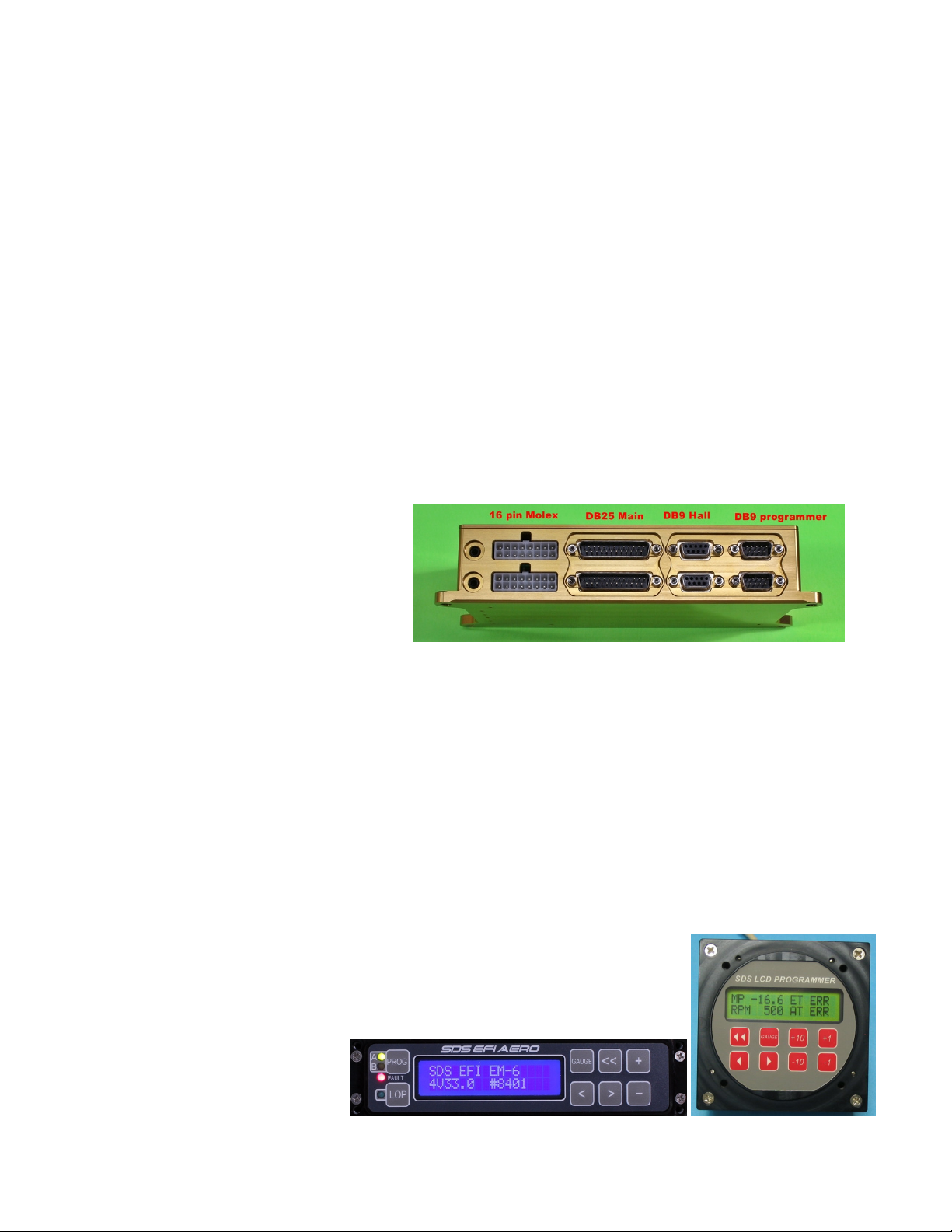
EM-6 ECU connectors
Injector drive Main harness Hall Programmer
Dual ECU
The dual board ECU enclosure stacks 2
boards in a single box. The upper board,
closest to the lid, is the Primary or “A”
computer. The lower, closest to the
mounting flange is the Backup or
“B”computer. The optional PC data
logging function can only be connected to the “A” computer. On 4 cylinder models using the dual board
ECU, there is no TPS, air temperature sensor, CHT sensor or mixture knob connected to the backup
computer since these are non-critical to running the engine. 6 cylinder dual board models use two air
temp and two CHT sensors, but share the TPS signal.
Dual board ECUs generally are used on engines with 2 spark plugs per cylinder. One ECU board drives
the upper plugs and the other board drives the lower plugs at all times. A relay switch box is used to
switch injector outputs between the 2 boards. The upper board is the Primary ECU, lower is the Backup.
Hole spacing for the ECU is 3.37 X 8.08 inches. Use the 10-32 stainless socket cap screws provided.
Nut plates are recommended.
SDS Programmers
The EM-6 comes with either the Design1-6.25” rectangular, or Round 3-1/8”
panel mount programmer which is used to adjust fuel and ignition timing values
and also display engine sensor data on several gauge screens. Both
programmer designs are Single ECU or Dual ECU capable as they have 2
DB9 ports on the rear to connect to the ECU be it Single or Dual ECU. The
programmer can be toggled to
either ECU as needed using the
Prog key or toggle switch(3-1/8”).

16
4 Cylinder
Switches and Breakers recommendations, Dual ECU
*** If Dual ECU using older round 3-1/8” programmer, add 1 more switch for ecu select, and if LOP
operation will be used, add 1 more switch again to arrive at a total of 9 switches. Add one 2A breaker for
the Fault LED light for a total of 14 Breakers.
The more modern Design1 6.25” wide programmer has its own ECU Pri/Bak select key and a LOP key
on its keypad.
Several items above do not need switches, but can just turn on with the Main Buss power
switch/contactor.
Some of the above options may not be needed such as the Octane Switch or Closed Loop switch so this
will change the total number of switches required.
Fuel pumps and ignition coils need dedicated switches to allow for individual function testing or “mag
check”.
Item Breakers
Quantity
Breaker
Amps
Switches
Quantity
Switch
included in
system
Fuel Pumps 2 15 2, SPST No
ECUs 2 2 Optional, SPST No
Ignition Coils 2 10 2, SPST No
Injectors 4 5 None Not needed
Injector Relays 1 2 1, to ground SPST Yes
Wideband
Controller
1 5 None. Relay
control through Pin
1 on 16 pin Molex
Not needed
Octane Select 0 None, switches ecu
input to ground.
1, SPST. Pin 10 on
16 pin Molex, switch
to ground.
No
SDS Card Logger 1 2 No Not needed
Closed Loop
Quick Enable/
Disable Switch
0 None, switches ecu
input to ground.
1, SPST, Pin 9 on 16
pin Molex, switch to
ground.
No
Totals 13 Breakers
Total***.
7 Switches
Total ***.

17
4 Cylinder Single Power Bus Schematic
*LOP switch only needed if using 3-1/8” programmer. Design1 Rectangular programmer has a built in
LOP Key on the keypad.

18
6 Cylinder Single Power Buss
Switches and Breakers recommendations, Dual ECU
* If Dual ECU using older round 3-1/8” programmer, add 1 more switch for ecu select, and if LOP
operation will be used, add 1 more switch again to arrive at a total of 9 switches. Add one 2A breaker for
the Fault LED light for a total of 14 Breakers.
** Injector relay switch: We supply a DPDT in event that customer wants to change to a Dual Power
Buss type system in the future. The switch 2nd Pole could be left unused, or it could be used for indicator
lights or fed to EFIS for switch position indication. If you change out this switch to a different type, make
sure it has a center Off position!
The more modern Design1 6.25” wide programmer has its own ECU Pri/Bak select key and a LOP key
on its keypad, so no need for a mechanical switch for these two functions..
Several items above do not need switches, but can just turn on with the Main Buss power
switch/contactor.
Fuel pumps and ignition coils need dedicated switches to allow for individual function testing or “mag
check”.
Item Breakers
Quantity
Breaker
Amps
Switches
Quantity
Switch
included in
system
Fuel Pumps 2 15 2, SPST No
ECUs 2 2 Optional, SPST No
Ignition Coils 2 10 2, SPST No
Injectors 6 5 None No
Injector Relay 6cyl 1 2 1, DPDT** On-Off-On
(Center Off)
Yes
Wideband
Controller
1 5 None. Relay control
through Pin 1 on 16
pin Molex
Not needed
Octane Select 0 None, switches ecu
input to ground.
1, SPST. Pin 10 on 16
pin Molex, switch to
ground.
No
SDS Card Logger 1 2 No Not needed
Closed Loop
Quick Enable/
Disable Switch
0 None, switches ecu
input to ground.
1, SPST, Pin 9 on 16
pin Molex, switch to
ground.
No
Mixture Knob relay 1 2 None Not needed
Totals for
6cyl Single
bus.
16
Breakers
Total.
7 Switches
Total *

19
6 Cylinder Single Power Buss Schematic
*LOP switch only needed if using 3-1/8” programmer. Design1 Rectangular programmer has a built in
LOP Key on the keypad.
Please also read about the Dual Power Buss option since the manual makes reference to Single Power
Buss and Dual Power Buss in some sections and being aware of this will reduce confusion. Dual Power
Buss info comes next.

20
6 Cylinder Dual Power Buss*
Switches and Breakers recommendations, Dual ECU
*Dual Power Buss means that normally both busses are powered on all the time and both ECU’s are
running all the time when the engine is running. Both Busses each have their own alternator and battery.
Power Buss A powers the Primary ECU & injectors 1,2,3 and Power Buss B powers the Backup ECU &
injectors 4,5,6. Each Buss powers an ignition coil pack on systems doing ignition control. The Injector
Relay Switch can redirect injector +12V power to either power bus when the switch is in PRI or BAK
positions and also redirect all 6 injector signals to either the PRI or BAK ecu. Dual Buss design is an
option when the airplane has dual high amperage alternators. If your 2nd alternator is lower amperage
emergency backup type do not choose the Dual Buss method.
*** If Dual ECU using older round 3-1/8” programmer, add 1 more switch for ecu select, and if LOP
operation will be used, add 1 more switch again to arrive at a total of 9 switches. Add 1 more 2A breaker
for Fault LED for a total of 19 Breakers.
The more modern Design1 6.25” wide programmer has its own ECU Pri/Bak select key and a LOP key
on its keypad.
Several items above do not need switches, but can just turn on with the Main Buss power
switch/contactor.
Some of the above options may not be needed such as the Octane Switch or Closed Loop switch so this
will change the total number of switches required. Fuel pumps and ignition coils need dedicated switches
to allow for individual function testing or “mag check”
Item Breakers
Quantity
Breaker
Amps
Switches
Quantity
Switch
included in
system
Fuel Pumps 2 15 2, SPST No
ECUs 2 2 Optional, SPST No
Ignition Coils 2 15 2, SPST No
Injectors 6 5 None No
Injector power Bus A 1 15 None No
Injector power Bus B 1 15 None No
Injector Relay 6cyl &
Knob Relay
2 2 1, DPDT On-Off-On
(Center Off)
Yes
Wideband Controller 1 5 None. Relay control
through Pin 1 on 16
pin Molex
Not needed
Octane Select 0 None, switches ecu
input to ground.
1, SPST. Pin 10 on 16
pin Molex, switch to
ground.
No
SDS Card Logger 1 2 No Not needed
Closed Loop Quick
Enable/ Disable
Switch
0 None, switches ecu
input to ground.
1, SPST, Pin 9 on 16
pin Molex, switch to
ground.
No
Totals for
6cyl Single
bus.
18
Breakers
Total.
7 Switches
Total ***.
This manual suits for next models
2
Table of contents
Other SDS GPS manuals


