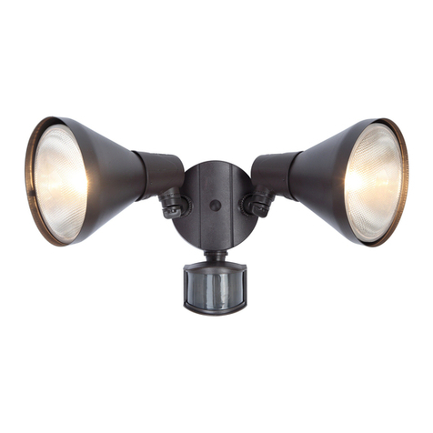
Sea-Dog 405620-3 Installation instructions

Installation
& Operation Instructions
Deluxe Spot & Flood Light
405620-3
To avoid the risk of accidents or
damage to this product, it is essential
to read these instructions thoroughly
before this product is installed and used. SDG 11-13

1
Contents
Product Features………………………………………………2
Specifications…………………………………………………..2
Installation………………………………………………………3
Spot Light Installation…………………………………….3
Diagrams…………………………………………………..4
Joystick Control Panel Installation……………………...5
Operation……………………………………………………..…6
Joystick Operation…………………………………….….6
Caution……………………………………………………….…7
Maintenance……………………………………………………7
Troubleshooting………………………………………………..8
Warranty Info……………………………………………….…..9

2
ProductFeatures
Certified in compliance with IEC 60598-2-5:1998 (safety), EN 55015 + EN 61547 (CE), EN
01 489-1/-3 + EN 300 440-2 (RF), EN 60945 (marine), and IP67 (protection).
Two light modes: spot light and flood light.
355° dual speed horizontal rotation, 50° vertical range.
Remote models can use multiple remote controls
Reliable digital remote control signal and resistant to interference.
Uses RJ11 telephone line. Simple connection compared to traditional wire harness.
Cast aluminum body with corrosion-resistant coating.
Completely sealed and waterproof.
12 Volts DC
Specifications
Material Aluminum body, glass front cover
Light Source Halogen H4 light bulb (100/90 Watts)
Light Coverage 0.25 Lux @ 849 m
Light Mode Spot light, flood light
Rotation 355° horizontal (dual speed), 50° vertical, jam protection
Power Cable 5 ft
Power Supply 12 V DC
Size L x W x H 8 x 8 x 10 inches
Weight 3.8 kg / 8.5 lbs
Control Joystick control, 2.4GHz remote control
Panel Connection RJ11 6P4C Pin 1-1 straight through, 15 ft / 25 ft / 35 ft
Controls Available Separately
A 12V Powered wireless remote is available (sold separately) for use as a second station control.
Please see our website www.sea-dog.com for more details.

3
Installation
Tools Needed for Installation
Electric drill
1” hole saw or drill bit
Jigsaw or small keyhole saw
Phillips head screwdriver
Crimping/cutting tool
User Supplied Items
Four (4) ¼” screws or bolts/nuts
10A fuse and fuse holder
Two (2) #8 self-tapping screws
Two (2) 10 – 12 gauge butt connectors
12 gauge wire in needed length less than 30 ft. and 10 gauge wire for longer runs
Spot Light Installation
1. The spotlight should be installed on a flat, level, non-metallic surface.
NOTE: If the spotlight is installed on a metallic surface, there must be 1-1/4” clearance
between the spotlight and the metal surface in order to allow the operation of the
wireless remote control (not included and sold separately, part number 405683-1).
See drawing #1 on page 4.
2. Use the foam gasket to mark the spotlight mounting holes and wiring access hole -
1”/25.4mm diameter – and drill the wiring access hole. See drawing #2 on page 4.
3. Connect the RJ11 joystick control panel phone cable to the base of the spotlight and
route the power wires and the joystick control panel cable through the wiring access
hole in the gasket and the deck.
4. Ensure that the foam gasket is properly seated and fasten the spotlight to the surface
using four ¼” self-tapping screws or four ¼” bolts and nuts.

4
!Do not mount directly onto metal surface; remote control will not work.
!Provide at least 1-1/4 inch (32 mm) clearance underneath the mounting surface to allow reception
of remote signal. Remote control may not work if clearance is insufficient.
Drawing #1
Drawing #2

5
Wiring
1. Use 12 gauge wire for distances up to 30 feet (9 meters) and 10 gauge wire for longer
runs.
2. Use a 10A fuse and fuse holder or circuit breaker connected to the positive terminal.
See drawing #3 below.
NOTE: The power switch on the joystick panel should be in the off position before
supplying power to the spotlight.
Joystick Control Panel Installation
1. The joystick control panel should be installed on a flat surface. The panel is watertight
and moisture resistant, but should be installed in a protected location to allow proper
operation.
2. Use the foam gasket to mark the mounting holes and rectangular hole (3-1/2” x 2-3/8”)
for the panel and cut out the hole. See drawing #4 on page 6.
3. Pull the RJ11 phone line cable from the spotlight through the mounting hole and
connect it to the panel.
4. Remove the frame/cover from the panel, remove the clear protective coating, and fit
panel into the rectangular hole. Secure the control panel with two #8 self-tapping
Drawing #3

6
screws or two #8 bolts and nuts and replace the frame/cover.
NOTE: The vertical and horizontal movements of the spotlight are controlled by the joystick.
The speed switch is for the horizontal rotation only. See drawing #5.
Operation
Joystick Control
1. The control of spot light by joystick is straightforward. The vertical movement is controlled by
moving the joystick forward and back. The horizontal movement is controlled by moving the
joystick left and right.
2. The speed switch is for horizontal rotation only. See drawing #5 below.
Drawing #5
Drawing #4
Joystick Control
Power Switch

7
Caution
1. Do not try to move the spotlight head beyond its normal horizontal or vertical range as
it will damage the spotlight.
2. Do not look directly into the spotlight when the light is turned on.
3. Given that the spotlight is powder-coated aluminum and is waterproof, it is
recommended that a cover NOT be used with this light. If a cover must be used, be
careful that the light it is not accidentally turned on because the heat build-up may
result in a fire.
Maintenance
1. Use a diluted mild liquid cleaner or cleanser for general cleaning – do not use harsh
chemicals or strong abrasives cleaners.
2. All moving parts are sealed and lubricated during production – no additional lubrication
is needed.
Serial Number Location
The individual product serial number is located on the lower left side of the spotlight
frame, this is visible when the frame is removed. See drawing #6 above. The serial
number is also on the box.
Drawing #6

8
Troubleshooting
What to do if …
… the spot light does not respond to remote control.
Press and hold button for 2 seconds.
Move to a location that is less than 15 m away.
Move to a location that has no obstructing structure between remote control and spot light.
Make sure the light is not mounted on any metal surface and there is sufficient clearance below.
Replace battery for remote control.
Check whether the last digits of serial numbers inside light housing and inside remote control are
identical.
… the light cannot be turned on.
Secure light bulb.
Replace light bulb.
Check if correct type of telephone line (RJ11 6P4C Pin 1-1 straight through) is used.
… the spot mode or flood mode does not function.
Replace light bulb.
… the spot light does not respond to any control.
Check voltage of inboard battery.
Check the fuse or circuit breaker that protects spot light and joystick control panel.
Carefully uninstall the spot light. Examine the electrical connections and wire harness.
Check if correct type of telephone line (RJ11 6P4C Pin 1-1 straight through) is used.
!Do not replace a blown fuse until the cause of spot light malfunction is identified and resolved.
!DO NOT replace a blown fuse with a fuse that takes higher current.
… the spot light halt during operation.
Return spot light and joystick control panel to dealer for further inspection.
… the spot light cannot rotate in certain direction.
Installation work and repairs to electrical components of this product must only be
carried out by a suitably qualified and competent person in accordance with current
local and national safety regulations. Repairs and other work by unqualified persons
could be dangerous. The manufacturer cannot be held liable for unauthorized work.

9
Carefully uninstall the spot light and examine the electrical connections and wire harness.
Replace joystick control panel.
… the brightness of the light significantly decayed.
Replace light bulb.
For other problems, and when problem is not solved with the above tips …
Return complete product with proper packaging to dealer for inspection. Include a description of the
problem, user contact information, and proof of purchase if requesting warranty service.
LimitedWarranty
Sea-Dog LIMITED FIVE YEAR WARRANTY
SEA-DOG warrants that this product manufactured by SEA-DOG is free from defects
in workmanship or materials for a period of 5 years from the date of purchase. No
other express warranty is given and no affirmation of SEA-DOG, by words or action,
will constitute a warranty. This warranty does not apply to any defects caused by
negligence, misuse, or accidents, improper installation, or use in violation of the
accompanying instructions and intended purpose. During warranty period, defects
will be repaired or the defective product will be replaced, at SEA-DOG’s option,
without charge.
The buyer must notify SEA-DOG of any defect, malfunction, or nonconformity within
thirty (30) days after discovery of such defect, malfunction, or nonconformity.
SEA-DOG's maximum liability shall not, in any case, exceed the contract price for the
product claimed to be defective or unsuitable. Any and all implied warranties are
limited to the duration of this Limited Warranty, which is 5 years from the date of the
purchase. Some States do not allow the exclusion or limitation of implied warranties
or consequential or incidental damages, so the above limitations or exclusions may
not apply to you. This warranty gives you specific rights, and you may also have
rights that vary from State to State.
Date Purchased___________________
Serial Number____________________
Table of contents
Popular Floodlight manuals by other brands
American DJ
American DJ Micro Galaxian User instructions
Gewiss
Gewiss COLOSSEUM GW 84 646 quick start guide

Robus
Robus RHL1030-04 manual
EXTOL LIGHT
EXTOL LIGHT 43122 Translation of the original user manual
Hubbell
Hubbell Progress Lighting PCOLF Series Installation instructions manual
Altman
Altman Phoenix Series Operation, programming and safety manual
Knightsbridge
Knightsbridge FLP Series Installation & maintenance manual
Show Atelier
Show Atelier DIALighting LED Par IP65 White user manual
Martec
Martec Patrol MLXP34520MS instruction manual
Kemot
Kemot URZ3225 owner's manual

Hoftronic
Hoftronic 7439628522572 user manual

Milwaukee
Milwaukee M18 HAL user manual
