Sea Tel Side Exit User manual


Procedure, Field Replacement, Level Cage Kit, Side Exit
Page1of8
Document No
135265 Rev B
Copyright © Sea Tel, Inc 2011 - The information contained in this document is proprietary to Sea
Tel, Inc.. This document may not be reproduced or distributed in any form without prior written
consent of Sea Tel, Inc.
1. BriefSummary:
Troubleshootingdocumentfordiagnosingafaultwithandreplacingthelevelcageassembly.
2. Checklist:
VerifyRemoteTilt
VerifyInitialization
VerifySensorOutputsusingDacRemP
AzimuthandRelativeTargeting
DriftandSensorMonitoring
3. TheoryofOperation:
Thelevelcagecontains4sensors,afluidfilledtiltsensorwhichisusedasthesystemshorizonreference(levelposition)
aswellaslongtermstabilizationreference,and3solidstateratesensors;oneforeachaxiswhichactastheantennas
shorttermstabilizationreference.Afaultysensorinsidethelevelcagewillcausetheantennatolosestabilityand
mispointfromthesatelliteunderdynamicconditions.However,thesystemmayappeartobeoperationalintheport
whenthereisnomotiontocounteract.Thisdocumentwillrunthroughtestingthesensorsinsidethelevelcage,
replacingthelevelcageassemblyandcalibratingthesystemsremotetiltsetting.
4. VerifyRemoteTilt:
Ifthepedestalishavingstabilityproblems,firstly,checktheremotetiltsettingbylookingatthelevelbubbleontopof
thelevelcage(note:oldersystemsdidn’thaveabubbleinstalledontopofthelevelcage).Itisonlypossibletodoso
whenthevesselisstationary.Ifthebubbleisn’tasclosetocentralaspossible,theremotetiltsettingisn’tcorrectly
calibratedmeaningtheratesensorswon’tbecorrectlyalignedwiththeiraxis.Thiswillcausetheratesensorstooutput
incorrectfeedbackintothePCU’scontrolloop,potentiallycausingastabilizationissue.Calibratetheremotetiltsetting
aspertheinstructionsattheendofthisdocumentandcontinuetotestthelevelcageusingthefollowprocedures.
5. VerifyInitialization:
Powercyclethepedestal
1. Brakesrelease(ifapplicable)
2. Levelcagedrivestoitsendstopandthenbacksoffexactly45degrees.Elistrackedbasedonstepsissued
bytransistorsinthePCU.
3. Elevationaxisdrivesto45degreesbasedonfeedbackfromthelevelcagestiltsensor.
4. Crosslevelaxisdrivestolevel,againbasedonfeedbackfromthetiltsensor.
5. Unlimitedazimuthsystemsdriveclockwiseuntilthehallaffectsensor/switchseesthehomeflag(magnet
ornotch)ontheAZdrivepulley.
6. Limitedazimuthsystemsdriveclockwiseintotheend‐stopthendrivesCCWawayfromthestop.Ifa
6003A/6004system,theRELwouldatthispointbe580.0degrees.
Ifanyofthesestepsfail,ortheACUreportsmodel"xx03/xx97",theantennasN0parameterneedscalibrating.Once
entered,verifythattheparameterhassavedcorrectlytothePCU’sNVRAM.Amotordriveissueorpedestalerror
requiresfurthertroubleshooting.
Procedure, Field Replacement, Level Cage Kit, Side Exit
Page2of8
Document No
135265 Rev B
Copyright © Sea Tel, Inc 2011 - The information contained in this document is proprietary to Sea
Tel, Inc.. This document may not be reproduced or distributed in any form without prior written
consent of Sea Tel, Inc.
6. VerifyStabilization:
Usingthebelowprocedurewewillphysicallymovethesystemsaxisunderstaticconditions,thusintroducinganerror
intothePCU’scontrolloop.Thiswillallowustoverifythatthesystemisabletoreturntoitslevelposition(stabilizeitself)
efficiently.WeareabletomonitorthesensoroutputsonDacRemPtoobservewhatishappening,orwecanjustwatch
thepedestalandobservehowitresponds.
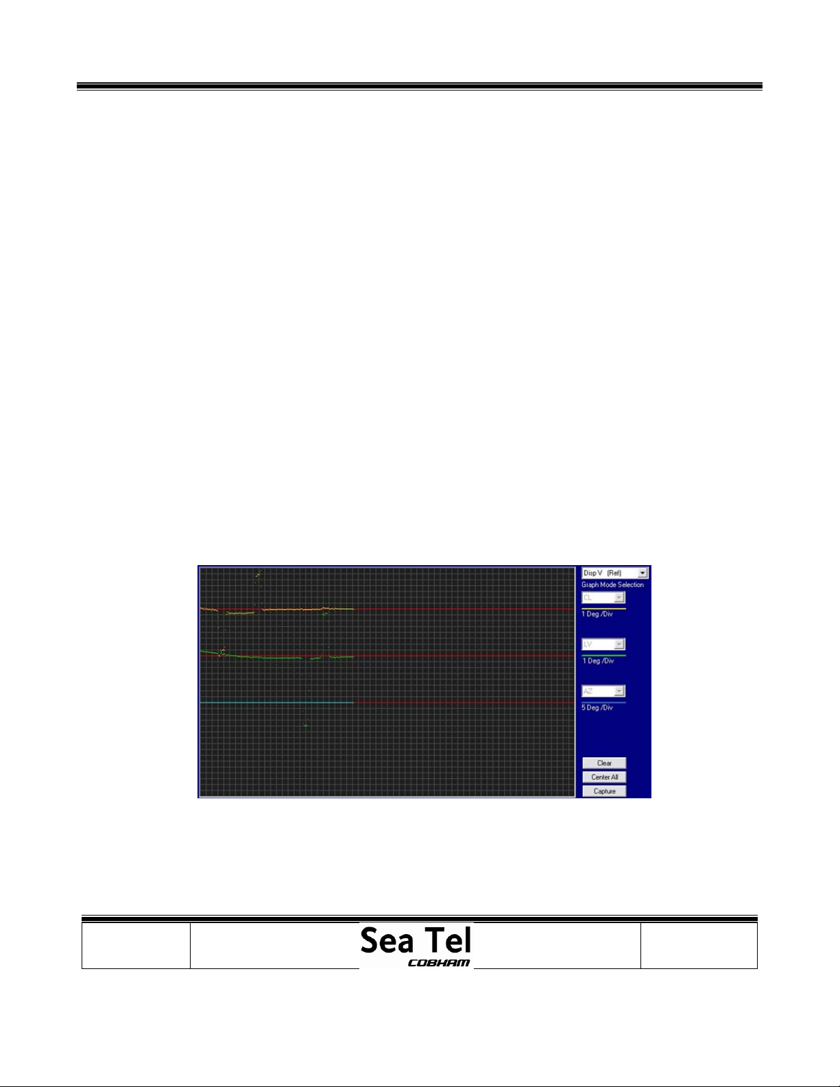
1. Turndishscanandtrackingoff.SelecttheDISP_VchartofDacRemP;youwillseethecurrentoutputfromthetilt
sensoringraphform.Oncearemotetilthasbeensetandwheninstableconditions,thetraceshouldbestableand
nomorethan+/‐4divisionsfromtheredreferenceline.Ifoutsidethislimitthenre‐checktheremotetiltandthenif
necessary,replaceandre‐calibratethelevelcage.
2. VerifyCrossLevelresponse:
Pushthecrosslevelbeamdowntotheleft(CCW)andholditinposition.VerifythattheCLtraceonDacRemP
movesdownanequalamounttothemovementexertedontheaxis.ReleasetheCLbeamandverifythatthe
DacRemPtracereturnsbacktoitsoriginalposition,withoutdeviatingortakingtimetosettle.Nowpushthecross
levelbeamdowntotherightandholditinposition.ThistimeverifythattheCLtraceonDacRemPmovesupan
equalamounttothemovementexertedontheaxis.ReleasetheAxisandverifytheDacRemPtraceandcrosslevel
beamreturnbacktotheiroriginalpositions,withoutdeviatingortakingtimetosettle.
3. VerifyLevel(Elevation)response:
PushthereflectorupinElevationandholditinposition.VerifythattheLVtraceonDacRemPmovesdownanequal
amounttothemovementexertedontheaxis.ReleasetheaxisandverifytheDacRemPtracereturns(orthe
systemsaxisreturns)backtoitsoriginalposition,withoutdeviatingortakingtimetosettle.Pushthereflectordown
inelevationandholditinposition.VerifythattheLVtraceonDacRemPmovesupanequalamounttothe
movementexertedontheaxis.ReleasetheaxisandverifytheDacRemPtracereturns(orthesystemsaxisreturns)
backtoitsoriginalposition,withoutdeviatingortakingtimetosettle.
IfusingDacRemPthetraceshouldlooksimilartotheimagetotheleft.Notehowaftereachmovementthesystem
returnstoitslevelpositionefficientlywithouttakingtimetosettle.

Procedure, Field Replacement, Level Cage Kit, Side Exit
Page3of8
Document No
135265 Rev B
Copyright © Sea Tel, Inc 2011 - The information contained in this document is proprietary to Sea
Tel, Inc.. This document may not be reproduced or distributed in any form without prior written
consent of Sea Tel, Inc.
7. RateSensorMonitoring:
RatesensoroutputscanalsobemonitoredusingtheDISP_WscreenofDacRemPtoverifyanydeviationsunderstatic
conditions.Thetracesshouldremainconsistent.Anydriftingorspikesareanindicationthesensorsvoltageoutputis
changingandthesensorisdefective(providednoforcesarebeingexertedonthesystem).Normaltraceis+/‐1division
fromredline.
8. AzimuthTargeting:
Shouldtheantennahaveissuestargetinginazimuth,suchasnotaccuratelyfindingthesatelliteorrepeatedlyfindingthe
satelliteindifferentazimuthpositions,thenit’simportanttodiagnoseifthesystemismispointinginazimuthorrelative.
RelativefeedbackfromtheAZencodercanbeverifiedbyinitializingthesystem,verifyingitcalibratesitselfcorrectlyand
thendrivingthepedestalclockwisein90degreeincrementsovera360degreerotation.Makenotethatthesystem
pointscorrectly(bow,starboard,aft,port,bowandstarboard)andthatnoAZreferenceerrorisflaggedbythePCU.A
mechanicalproblemsuchasthebeltslippingonthepulleycouldalsocausethiskindoferror,ascouldsomeother
mechanicalissue.Skewingtheantennainazimuthbyholdingtherightorleftarrowkeytodrivetheantennaslowlymay
alsopresentanissue.
Ifthesystemkeepsfindingthesatelliteatdifferentazimuthpositionsbutatthesamerelative,theencoderisfunctioning
correctlyandoneofthereferenceinputs(Levelcage,gyro)tothePCUiscausingtheantennatomispoint.
9. Drift:
Anotherfailurewhichcanoccurisifaratesensorstartsdrifting;thismeansthesensorsvoltageoutputdeviatesfrom
whatthePCUisexpectingunderstablecondition(2.50VDC).Thisfaultwillintroduceanerrorintothecontrolloop.Itis
morecommontoseethisintheAzimuthaxisastheCLandELaxishavethetiltsensorastheirlongtermreference
(althoughshouldtheratesensorsdriftbelargeenoughtooverpowerthetiltsensoryouwouldseethesystemdriving
intooneoftheCLorELendstops).Thisismorenoticeablewithtrackingturnedoff.
ToverifyifthesystemisdriftinginAzimuth,firstturnofftrackingandthenmonitortherelativeposition.Understatic
conditions(thevesselsheadingisn’tchanging)therelativeshouldremainstill.Iftherelativevaluebeginsto
increase/decreasefromitsnominalpositionthentheazimuthratesensorisdrifting,creatinganerrorintothePCU’s
controlloop.ThiswillcausethePCUtobelievethevesselsheadingischangingandinturndrivetheazimuthaxisinthe
oppositedirectiontocompensate.

Procedure, Field Replacement, Level Cage Kit, Side Exit
Page4of8
Document No
135265 Rev B
Copyright © Sea Tel, Inc 2011 - The information contained in this document is proprietary to Sea
Tel, Inc.. This document may not be reproduced or distributed in any form without prior written
consent of Sea Tel, Inc.
10. Diagnostics:
Anyincorrectreadingsfromtheabovetestswouldrelatetoanerrorintheantennascontrolloopcausingthesystemto
notstabilizecorrectly.Themostlikelycauseofthisisadefectivesensorinthelevelcage.Thenextstepwouldbeto
replaceandre‐calibratethelevelcage.Nowrepeatthefailedtesttoverifythatthesystemisnowfunctioningcorrectly.
Shouldtheproblemremain,anotherpossiblecausemaybeafaultwiththereferenceharnessbetweenthelevelcage
andPCU.ThePCUitselfshouldnotberuledoutasfaultyeither.Evenso,thelevelcageisthemostlikelycomponentto
becausingthisissue,thereforereplacingitisthefirststepwhentroubleshooting.
Oncetheproblemhasbeenrectified,itisgoodpracticetorefittheoriginallevelcageandseeifthefaultreturns.Itis
possiblethatcorrosiononthepinsofthereferenceharnessand/orconnectorsofthePCU/levelcagecausedtheinitial
fault.Byconnectingthereplacementlevelcage,itislikelythatanypincorrosionmayhaverubbedoff,creatingacleaner
electricalcontact.Youmayhavebeenundertheimpressionthatreplacingthelevelcagerectifiedthefaultwhenin
actualfact;theissuewasapoorelectricalcontactcausingvaryingresistance.
11. FurtherInformation:
Shouldthesystemfailtotargetthecorrectelevation(physicallypointingatadifferentpositiontothereadingonthe
DAC),orhaveissuesdrivingpastacertainelevationpositionthenthemostlikelycauseisadefectivelevelcagemotor.
Ifthesystemisdisplayingapedestalerror(error8),thereisadriveissuewiththeantennaandattentionwillneedtobe
paidtothemotorandmotordriver(servoamp)fortherelevantaxis.Thereisnoerrorcodethatdirectlytellsyouifthe
levelcageorlevelcagesteppermotorhasfailed,however,apointingorstabilizationissueisagoodindication.
Anotherpotentialissuewhichcouldcausetheantennatolosethesatelliteisifthevesselsgyrocompassisdrifting.This
accumulatingerroristhenfedintothecontrolloop.ThiscanbeverifiedbyrunningaDacRemPlogfileatseatomonitor
thepedestalsreadingswhentheAGCdrops,orbyputtingthesystemintosatellitereferencemodetouncouplethegyro
feedfromtheazimuthstabilizationloop.
Procedure, Field Replacement, Level Cage Kit, Side Exit
Page5of8
Document No
135265 Rev B
Copyright © Sea Tel, Inc 2011 - The information contained in this document is proprietary to Sea
Tel, Inc.. This document may not be reproduced or distributed in any form without prior written
consent of Sea Tel, Inc.
12. ReplacingtheLevelCageAssembly:
12.1. Tools.
2mmFlatBlade(Terminal)Screwdriver
#1PhillipsScrewdriver
½”Wrench/Spanner
12.2. Procedure.
Procedureforreplacingthelevelcageassembly,SeaTelkitpartnumber:135344(levelcageassemblypartnumber:
122208‐1)andtensioningthelevelcagebelt.
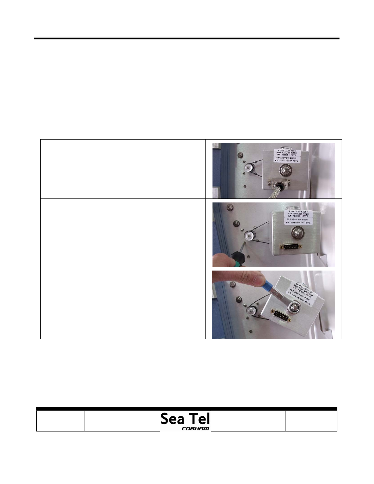
*CAUTION:Powerdownthepedestalbeforefollowingthis
procedure.
1.Usinga2mmflatbladescrewdriver,loosenthescrews
securingthereferenceharnessD‐Subconnectortolevelcage.
2.Usinga#1Phillipsscrewdriver,loosenthefourscrews
attachinglevelcagemotortotheELpan(donotfully
remove).
3.Usinga½”socketorspanner,removetheNylocknut
securingthelevelcagetothespindle.

Procedure, Field Replacement, Level Cage Kit, Side Exit
Page6of8
Document No
135265 Rev B
Copyright © Sea Tel, Inc 2011 - The information contained in this document is proprietary to Sea
Tel, Inc.. This document may not be reproduced or distributed in any form without prior written
consent of Sea Tel, Inc.
4.Slidethemotortowardsthelevelcagetoallowenoughslack
onthebelttoremoveitwithoutstressingit.
5.Removethedefectivelevelcage,takingcarenottoremove
thestandoffspacerfromthespindle.
6.Installthereplacementlevelcageontothespindle,slipping
thebeltoverthelevelcagepulleyandmakingsureitsend
stopsarealignedcorrectly.
7.Secureitwiththe1/2”Nylocknut.Whentight(sothatthere
isnohorizontalplayalongthespindle)addanadditional½a
turnforagoodground.Rotatethelevelcagebyhandand
verifyithas90degreesofmotionandthatthecagerotates
freely,ensuringthestopsdonotrubagainsttheELpan.
8.Tensionthebeltbyslidingthemotorassemblybyhand
awayfromlevelcageandthentightenthefourscrews.
9.Acorrectlytensionedbeltwillallow¼turnwithyourfingers.
Ifthebelttensionistootight/looseadjustuntilcorrect.
10.Ifthebelttensionisincorrectloosenthescrewsandre‐
tension.NoLoctiteisrequiredaslockwashersareusedonthe
securingscrews.
11.Re‐connectthereferenceharnesstothelevelcageand
tightentheretainingscrews,againnoneedtouseLoctiteas
lockwashersareinstalledontheconnectorshell.
Procedure, Field Replacement, Level Cage Kit, Side Exit
Page7of8
Document No
135265 Rev B
Copyright © Sea Tel, Inc 2011 - The information contained in this document is proprietary to Sea
Tel, Inc.. This document may not be reproduced or distributed in any form without prior written
consent of Sea Tel, Inc.
13. CalibratingtheRemoteTiltSetting:
Thisprocedureisrequiredtocalibratethelevelcagesothatallthesensorswillbeaccuratelyalignedtotheiraxis.The
fluidfilledtiltsensorprovidesatwodimensionalhorizonreference.Thesystemisnotabletoautomaticallycalculatethe
exactcentervalue,thereforeitisnecessarytoperformthisproceduretomanuallyenteranyoffsetrequiredtomakesure
thePCUreceivesatruehorizonreference.
1. Turndishscanoff:
EnterintotheSetupMenubypressingandholdingthearrowstogetheruntiltheELTrimorAutoTrim
parameterisdisplayed.
Usethearrowkeytoscrollthroughthemenuuntilthedishscanwindowisdisplayed.
Pressthearrowtoactivatethewindowandthenpressthearrow,followedbythebuttontoturn
dishscanfromontooff.
*Note:Whenyoupressthearrowtoturndishscanoffyouwon’tseethedisplaychangeuntilyoupressthe
button.
(Steps2‐7requiresassistancetoobserveandoperateantennasimultaneously)
2. EnterintotheSetupMenubypressingandholdingthearrowstogetheruntiltheELTrimorAutoTrim
parameterisdisplayed.
3. PushthearrowkeyuntiltheRemoteTiltwindowisdisplayed.
4. PushthearrowkeytoactivatetheRemoteTiltsetting.
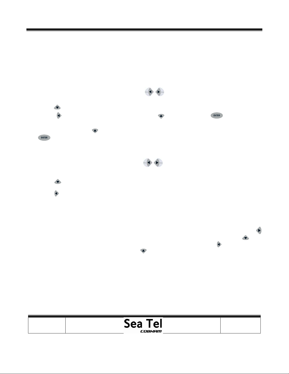
5. Usethearrowkeystopositionthebubbleasclosetothecenteraspossible.Eachpressofanarrowkeyonthe
directionalpadwillmovetheRemoteTilt½adegree.Itisadvisedthatyouonlypressthebuttononceandwaitfor
theaxistomovebeforepressingitagain.
Whenstandingbehindtheantennalookingatthebubble,ifthebubbleisovertotheright,youneedtopressthe
(right)arrowtobringthebubbleintothecenter.Ifthebubbleisdowntowardsyou,youneedtopressthe
(down)arrowtobringittowardsthecenter.Ifthebubbleistotheleft,youneedtopressthe(left)arrowandif
thebubbleisuptowardsthetop,youneedpressthe(up)arrowtomoveittowardsthecenter.

Procedure, Field Replacement, Level Cage Kit, Side Exit
Page8of8
Document No
135265 Rev B
Copyright © Sea Tel, Inc 2011 - The information contained in this document is proprietary to Sea
Tel, Inc.. This document may not be reproduced or distributed in any form without prior written
consent of Sea Tel, Inc.
Whencorrectthebubbleshouldbeasclosetothecenterofthefluidaspossible
6. WhenthebubbleisascentralaspossiblepressthebuttontodeactivatetheRemoteTiltsetting.
7. Turndishscanon:
EnterintotheSetupMenubypressingandholdingthearrowsuntileithertheELTrimorAutoTrim
parameterisdisplayed.
Usethearrowkeytoscrollthroughthemenuuntilthedishscanwindowisdisplayed.
Pressthearrowkeytoactivatethewindowandthenpressthearrowkey,followedbythebuttonto
turndishscanfromofftoon.
*Note:Whenyoupressthearrowtoturndishscanonyouwon’tseethedisplaychangeuntilyoupressthe
button.
8. SavetheRemoteTiltsettinginthePCU:
PressthearrowkeyuntiltheRemoteParameterswindowisdisplayed.
Pressthearrowkeytoactivatethewindowfollowedbythebutton(you’llseeaconfirmationonthe
displaysaying“Saved”).
9. AsgoodpracticemakeanoteofyourN4andN5parametersonceyouhavecorrectlysettheremotetilt.TheN4and
N5parametersareanumericreadoftheremotetilt.Todothisgototheremotecommandwindowandkeyin
N4999toreadtheCLsetting,followedbyN5999toreadtheELsetting.
Table of contents


