SEA USA GATE 1 DG R2BF User manual
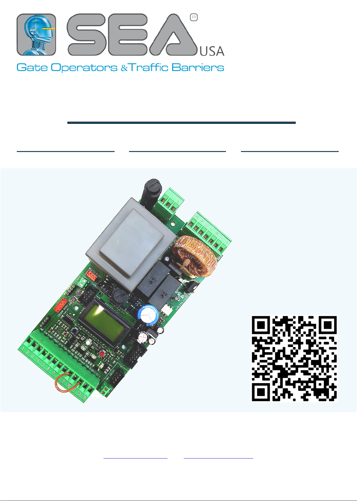
GATE 1 DG R2BF GATE 1 DG R2EF GATE 1 DG R3BF
67412252 REV. 00 - 06/2022
QUICK START
FULL MANUAL
(Rev. 15)
&
SAFETY
INFORMATION
SEA USA Inc.
10850 N.W. - 21st - unit 160 - Doral - MIAMI - Florida (FL) - 33172 - USA
Telephone - Toll free: : ++1-305.594.1151 ++1-305.594.7325 800.689.4716
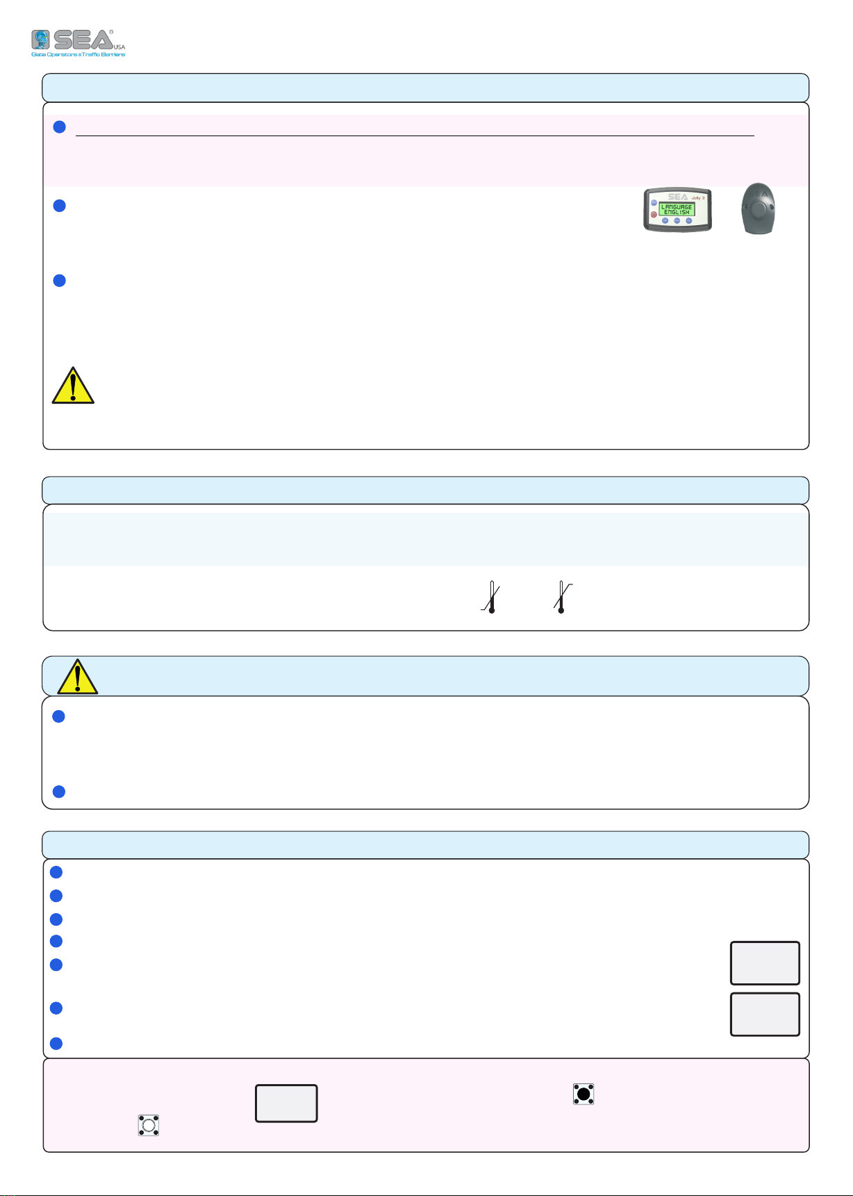
JOLLY 3 SEACLOUD
T
JOLLY 3
SEACLOUD
T GATE 1 DG (
7);
!
F
; ,
A (, )
;
PRELIMINARY
TECHNICAL INFORMATION
-
230V - 50/60 H
115V - 50/60 H
30 mA
-20° C +50°C
( )
IP 55
GATE 1 DG R2BF (SOFTWARE REV. 03.04)
QUICK START
F « 1 3» : ,
;
a
, ,
192
MOVE
GATE UP
DOWN
7
TIMER TO
CLOSE
3
MOTOR
M ( OFF): ,
DO NOT N.C. ( .. )
P ( 5)
O - «» ( 6)
S 7 «» ( )
«-» ( )
C 3 ( )
S 7
IMPORTANT SAFETY INFORMATION - RESET BUTTON
GATE 1 DG « » UL STANDARDS (UL325).
A , BUZZER .
T B , « »
C « » , 5 6 CN1
GATE 1 DG R2EF (SOFTWARE REV. 03.04) GATE 1 DG R3BF (SOFTWARE REV. 00.01)
2
1
Common
Light (-)
*24VAUX 500mA max.
-
UP DOWN OK
BLACK WHITE RED
+
EXTERNAL MODULE
CONNECTOR
JOLLY3/SEACLOUD
CONNECTOR
RF RECEIVER
CONNECTOR
PRIMARY
SECONDARY
CONNECTOR
OPEN
(Firmware update)
RF FIX RECEIVER
CONNECTOR
PROGRAMMING
BUTTONS
* A 24V 500mA, 24V
, (30 mA)
ANT COM START STPD STOP COM PH1 PH2 EDGE1 24VAUX COM 24V(FL) FL(-)
ANT COM START STPD STOP COM PH1 PH2 EDGE1 24VAUX COM 24V(FL) FL(-)
OPTIONAL JUMPERS
AUTOMATIC RECOGNITION OF THE
N.C. INPUTS NOT IN USE - NO JUMPER IS
REQUIRED ON THE N.C. CONTACTS
UP DOWN OK
TR1
98
7
6
5
4
3
2
110 13
12
11
CN1
98
7
6
5
4
3
2
110 13
12
11
CN1
CN1 CN2
JOLLY
CLOUD
CNS
CNS
CN4
CNA
DISPLAY
CMS
PRIMARY
SECONDARY
EXP
--------
--------
- - - - - - - -
- - - - - - - -
NL
CNP
CN7
CN6
CN5
20
19
18
17
16
15
14
20
19
18
17
16
15
14
CN2
CN3
F2
R1
R2
F1
T1
155 mm
85 mm
+
-
*24V 500mA max.
(accessories)
98
7
6
5
4
3
2
110 13
12
11
THE INPUTS EXCLUDED DURING THE
WORKING TIMES PROGRAMMING CAN BE
RESTORED THROUGH THE «INPUTS
MANAGEMENT» MENU (CHAPTER 7).
NO NEED TO SET UP THE UNIT AGAIN
NL
Courtesy light (phase)
Courtesy light (neutral)
Motor 1 opening
Motor 1 capacitor
LIGHT LIGHTN MCL MN MOP CAPACITOR
Motor 1 closing
Motor 1 neutral
M
CN3
Neutral
Line
CN4
24Vac *
Max. 150 mA
CN5
CN6
Red/Brown
Blue/White
Black/Green
CONNETTORE
ENCODER
1
Opening limit switch (green)
Closing limit switch (yellow)
Common (white)
* 24V (red)
Opening limit switch (green)
Closing limit switch (yellow)
CN7
CNP
T1
R1
R2
F1
F2
TR1
EXP JOLLY/CLOUD
CMS
CNA CNS
=
=
=
=
=
=
MOTOR CONTROL TRIAC
MOTOR AND COURTESY LIGHT RELAY
MOTOR EXCHANGE RELAY
FUSE 6.3AT (230V) OR 10AT (115V)
FUSE ACCESSORIES 1A
POWER TRANSFORMER
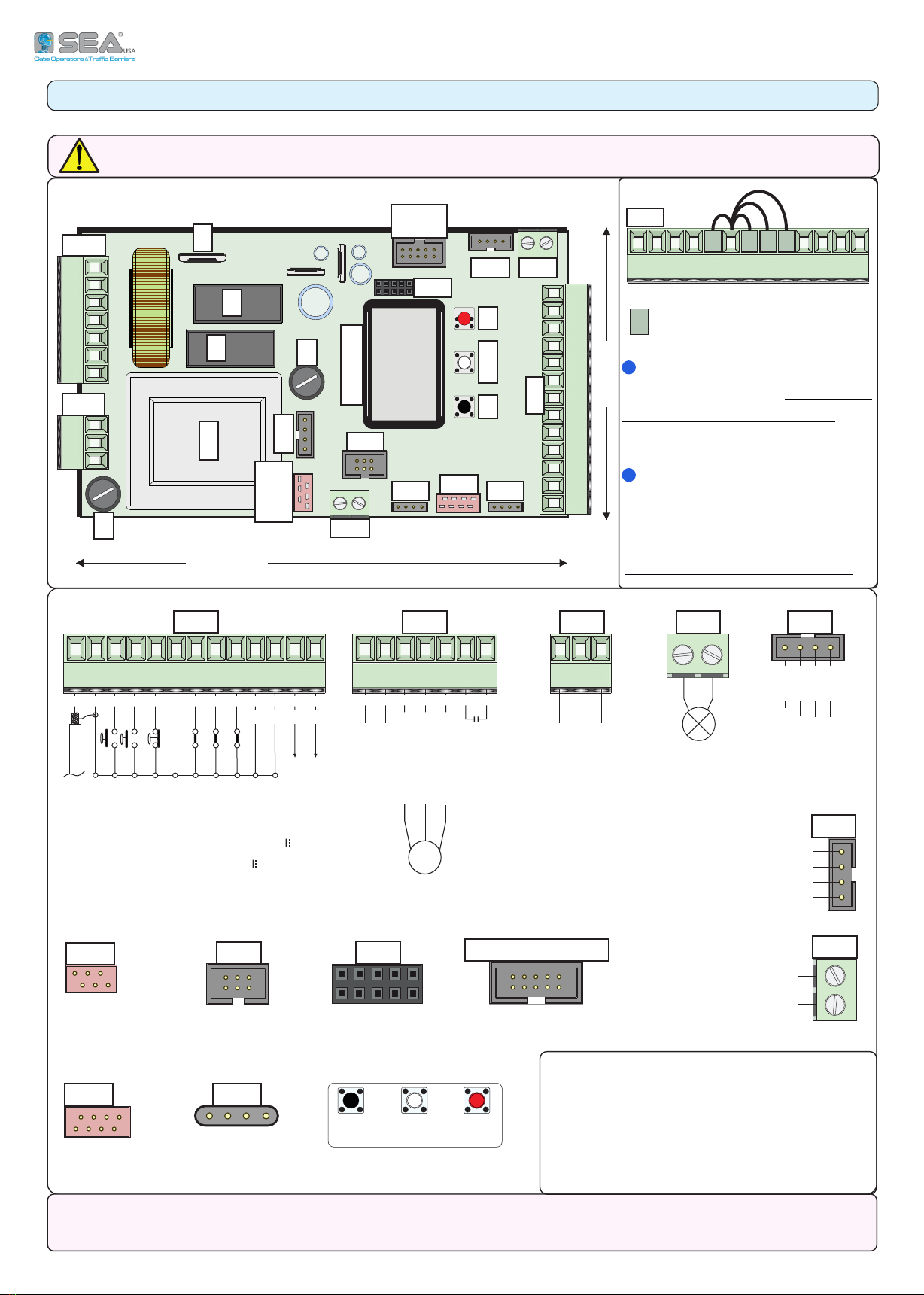
1 - CONNECTIONS
WARNING: CONNECT ALL DEVICES WHEN THE CONTROL UNIT IS SWITCHED-OFF
Start
Stop
Common
Antenna
Common
Photocell 1
Photocell 2
Partial START
Safety edge
3

2 - MAIN WIRINGS
EXAMPLES OF LIMIT SWITCH WIRINGS
EXAMPLE OF ENCODER WIRING
EXAMPLE OF
ANTENNA
START
PARTIAL START
STOP
PHOTOCELLS
WIRINGS
1
CN6
RED
RED = 24V
BLACK
YELLOW
YELLOW = CLOSING LIMIT SWITCH
13
12
11
10
9
CN1 CN7
GREEN
GREEN = OPENING LIMIT SWITCH
WHITE
WHITE = COMMON
CN5
1
2 1
OFF
DIP SWITCH 1 = OFF
DIP SWITCH 2 = OFF
P11
D1
P01
POTENTIOMETER
EXAMPLE OF POTENTIOMETER WIRING via «LSE» UNIT
M1
1 2 4 56 73
8
9 10 11
M2
DS1
2 1
ON
CN1
POT
ENC
CNP
+
-
P01 P02
GND
I3
D1 P11 D2 P12 I1 I2 I4
LSE
8
7
6
5
4
3
2
1
CN1
TX1
TX2
CN1
RX1
RX2
Start
Stop
Antenna
13
12
11
910
24V (+)
Common
Common
Common
Photocell 1
Photocell 2
Partial Start
YELLOW
GREEN
PRE-WIRED
LIMIT SWITCH
NON
PRE-WIRED
LIMIT SWITCH
(EXAMPLE)
BLACK
ENCODER NEW MODEL: BLACK - BLUE - RED
ENCODER OLD MODEL: GREEN - WHITE - BROWN
BLUE
RED
BLACK (WHITE) D1
BLUE (GREEN) P01
BROWN P11
98
710 12
11
CN1
Common
Edge 1
24V (+)
98
710 12
11
CN1
Photo 1
Photo 2
Common
CN1
13
12
11
10
9
-
+
BUZZER
Lamp FL(-)
7 8
24V (+)
EXAMPLES OF 10K PHOTOCELLS WIRINGS
10K PHOTOCELL
10K PHOTOCELL
UP TO 4 10K PHOTOCELLS
24V (+)
EXAMPLE OF 10K PHOTOCELL
AND BUZZER WIRINGS
EXAMPLE OF SAFETY EDGE AND
WARNING LAMP WIRINGS
Common
Edge 1
GATE 1 DG R2BF
GATE 1 DG R2EF
GATE 1 DG R3BF
YELLOW = CLOSING LIMIT SWITCH
GREEN = OPENING LIMIT SWITCH
BLACK = COMMON
13
12
11
10
9
24V (+)
SAFETY EDGE
Edge 1
Common
Lamp FL(-)
CN1
(EXAMPLE)
4

3 - OPERATOR WIRING ON CONTROL UNIT
CN2
20
19
18
17
16
15
14
MCL MN MOP CAPACITOR
a
OK UP
3
OK
4 - CONTROL UNIT POWER SUPPLY
NL
CN3
-
-
5 - INPUTS STATUS
00111110
1 2 3 4 5 6 7 8
9 10 11 12 13 14 15 16
1
2
3
4
5
6
7
8
9
10
11
12
13
14
15
16
11000000
-
-
-
-
01
00111110
11000000
START
(N.O.)
START
(N.C.)
10111110
11000000 11000000
00111110
11000000
00101110
= MCL - M1 CLOSING
= MN - M1 NEUTRAL (WHITE)
= MOP - M1 OPENING
= CAPACITOR
16
17
18
19 - 20
M
~
*
*
MOTOR 1 (115V)
BLUE 230V
(EXAMPLE)
CAPACITOR
O
A ,
3
SLIDING
MOTOR
(EXAMPLE)
T !
F 16AT 230V~
F 16AT 115V~
U 10A
F
I ,
UPS .800VA
E ,
E : (0) - (1)
N.O. - N.C. -
START
PARTIAL START
STOP
PHOTOCELL 1
PHOTOCELL 2
SAFETY EDGE 1
SAFETY EDGE 2
NOT IN USE
MOTOR 1 OPENING LIMIT SWITCH
MOTOR 1 CLOSING LIMIT SWITCH
NOT IN USE
NOT IN USE
NOT IN USE
NOT IN USE
NOT IN USE
NOT IN USE
PHOTOCELL 1
(N.C.) PHOTOCELL 1
(N.O.)
S P S N.O. (0) - A N.C. (1)
5
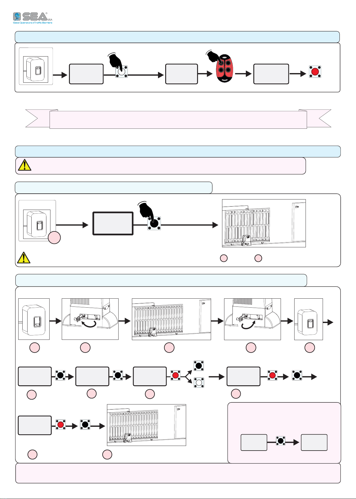
7 - WORKING TIMES LEARNING
ON
POWER ON
UP
TENERE PREMUTO
5 SECONDI
CHIUDE
APRE
CHIUDE
00111110
11000000
5
WORKING TIMES LEARNING PROCEDURE - MORE DETAILS ON TECHNICAL MANUAL
ON
POWER ON
00111110
11000000
DOWN OK
6 - «START» COMMAND QUICK LEARNING ON THE TX
a
HOLD PRESSED
5 SECONDS
EXIT
PRESS
BUTTON
STORED
HAVE A QUALIFIED SERVICE PERSON TO CARRY OUT THE OPERATIONS IN SAFE CONDITIONS
QUICK START - ONLY FOR SEA SLIDING OPERATORS
1
OFF
POWER OFF
23 4
POWER ON
ON
5
UP
11000000
00111110
03.04
UP OK
UP
DOWN
OK
OK
UP
UP
9
789
10
6
11
CLOSE - OPEN - CLOSE
UP
ON
5
a
UNLOCK LOCK
(EXAMPLE)(EXAMPLE)
LEAVES ON HALFWAY
(EXAMPLE)
3
MOTOR
1-HYDRAULIC
(EXAMPLE)
(EXAMPLE)
CHOOSE THE MODEL
PROGRAM-
MING
(EXAMPLE)
I
,
5:
REVERSE
MOTOR
T ;
F ,
! 1 5
F ,
!
6
SET DESCRIPTION DEFAULT NOTES
Italiano
Italian
English
English
Français
French
Español
Spanish
Dutch
Dutch
Start
Start
Partial opening
Partial opening
External module
External module
Stop
Stop
Bistable Stop
Pressed once, it stops the gate.
Pressed twice, it reactivates the START input
Latch opening
One impulse opens and keep open.
A second impulse restore the movement
Latch closing
One impulse closes and keep closed.
A second impulse restore the movement
Unlock
To store a command for unlocking the electric brake
Delete a transmitter
To delete a single transmitter (TX)
Move to EEP
Menu available on model
R3BF only
To transfer the transmitters stored on the control unit to
the external EEPROM (MEM), if connected
Clear memory
To delete the full transmitters memory on the receiver
End
To exit the menu "transmitters"
1- Hydraulic
Hydraulic operators
2- Sliding Sliding operators
3- Reversible Sliding Reversible sliding operators
4- Mechanic Swing
Electro-mechanic swing operators
5- Three-phase
and Bollards
Three-phase operators
Bollards
6- Magnetic Sliding Sliding operators with magnetic limit-switch
7- Barrier Barriers
12- B-200 Sliding operator
13- Chain sliding operator
Sliding chain operator
Slowdown OFF
deceleration 70%
Buzzer in ON
PHOTO 2 as shadow loop
14- B-200 chain Sliding chain operator
15- Erg Garage door operator
On
To reverse the opening with the closing and vice-versa
(both motors and limit-switches are reversed)
Off Off
3
MOTOR
Mechanic
1
LANGUAGE
English
2
TRANSMITTERS
Start
Partial
Opening
5
REVERSE MOTOR
Off
MENU
GATE 1 DG (R2BF) - (R2EF) - (R3BF) MENU FUNCTIONS TABLE
THE DESCRIBED FUNCTIONS ARE VALID FOR ALL GATE 1 DG VERSIONS, EXCEPT WHERE EXPRESSLY STATED
7

SET DESCRIPTION DEFAULT NOTES
Automatic
Automatic logic - automatic reclosing enabled
Open-stop-close-stop-open
Step by step type 1
Open-stop-close-open
Step by step type 2
2 button
Two buttons
Safety
Safety
Dead man
Dead man
Off
Semi-automatic logic enabled
(a START command opens and another START closes the
gate - automatic reclosing disabled)
1 240
To set a pause time (from 1 second to 4 minutes) before
the automatic reclosing
Off
The Start command is not accepted during pause
On
The Start command is accepted during pause
9
PROGRAMMING Off On To start the working times self-learning Off
10
TEST START Off On To give a Start command for testing the automation Off
13
LATCH PAUSE
Menu available on
model R3BF only
Off On
If "ON" the operator complies with the pause time set
when the function "LATCH OPENING" is disabled. When
"OFF" the pause time set is not respected
Off
14
RESET
192
MOVE GATE 1 *
Menu available on
model R3BF only
- - - -
15
END
16
SPECIAL MENU
MENU
6
LOGIC
Auto-
matic
7
TIMER TO CLOSE
Off
8
START IN PAUSE
Off
Press OK to return to the display of the firmware version
and to the one of inputs state
Press OK to enter the special menu
A count-down of 5 seconds will start by holding the UP button; at its end "INIT" will appear on the
display as confirmation of the control board reset
Allows the movement of the gate in a temporary "dead man" mode
(for example to test the correct running of the motor)
HOLD UP PRESSED = THE GATE OPENS
HOLD DOWN PRESSED = THE GATE CLOSES
* The command is accepted only at the end of the cycle or after a STOP command; it is not accepted during the cycle and
during the pause
8
SET DESCRIPTION DEFAULT NOTES
28
OPENING TORQ 1 10 100
Motor 1 opening torque:
by increasing the torque, more strength will be required
to execute the inversion in case of obstacle.
with hydraulic motors the torque will be on 100%
It
depends
on
model
29
CLOSING TORQ 1 10 100
Motor 1 closing torque:
by increasing the torque, more strength will be required
to execute the inversion in case of obstacle.
with hydraulic motors the torque will be on 100%
It
depends
on
model
32
ENCODER On
ON = Encoder enabled
OFF = Encoder disabled
(when OFF, the working times learnt are only shown)
Off
47 ENCODER PAR.
M1
xxx.
48 ENCODER TOT.
M1
xxx.
32
ENCODER Potentiometer
To enable the reading of the potentiometer
(only with LE or LSE management unit)
Off
51 I.PAR. M1 *- - - - - - - -
52 I.AP. M1
From the value learned
to ± 100 pulses
53 I.CH. M1
From the value learned
to ± 100 pulses
32
ENCODER Off
ON = Encoder enabled
OFF = Encoder disabled
(when OFF, the working times learnt are only shown)
Off
65 OPENING TIME M1 xxx.s
66 CLOSING TIME M1 xxx.s
10% (Fast intervention)
99% (Slow intervention)
To adjust the Encoder or Potentiometer intervention time
on Motor 1 in opening
Off (Intervention excluded) Disabled
10% (Fast intervention)
99% (Slow intervention)
To adjust the Encoder or Potentiometer intervention time
on Motor 1 in closing
Off (Intervention excluded) Disabled
10% (Fast intervention)
99% (Slow intervention)
To adjust the amperometric sensitivity in slowdown
Function available only on electro-mechanic operators
Off
With potentiometer
To set the inversion time in slow-down from 0to 5
seconds (= 99%) - Only with potentiometer enabled
It
depends
on model
Impulses read by Encoder during operation (Motor 1)
Impulses stored during programming (Motor 1)
To show the current position of the potentiometer on the leaf moved
by Motor 1. This parameter is useful to see if the potentiometer is
correctly read
To show the impulses stored by the control unit when the leaf moved
by Motor 1 is fully open
To show the impulses stored by the control unit when the leaf moved
by Motor 1 is fully close
To display the learnt value during the working times self learning, in
opening and closing (Motor 1) . With UP or DOWN it is possible to
increase or reduce the working times
33
OPENING SENSITIVITY
MOTOR 1
Off
37
SLOWDOWN
SENSITIVITY MOTOR
SPECIAL MENU
SPECIAL MENU
PRESS AT THE SAME TIME FOR 5 SECONDS TO ENTER OR TO EXIT THE SPECIAL MENU
34
CLOSING SENSITIVITY
MOTOR 1
Off
THE DESCRIBED FUNCTIONS ARE VALID FOR ALL GATE 1 DG VERSIONS, EXCEPT WHERE EXPRESSLY STATED
* While the partial impulses are displayed, it is possible to OPEN (by pressing UP) or CLOSE (by pressing DOWN) the operator
to verify the correct reading of the potentiometer - Function available only on model R3BF
9

SET DESCRIPTION DEFAULT NOTES
38
POTENTIOMETER
THRESHOLD
OPENING 1
39
POTENTIOMETER
THRESHOLD
CLOSING 1
42
POTENTIOMETER
SLOWDOWN THRESHOLD
OPENING 1
43
POTENTIOMETER
SLOWDOWN THRESHOLD
CLOSING 1
Total
In case of obstacle or safety edge it totally reverses the
movement during closing. If the automatic reclosing is
enabled (automatic logic) , it is attempted for 5 times
Partial
In case of obstacle, safety edge or potentiometer, it
partially reverses direction (of about 30 cm) then stops
59
OPENING
SLOWDOWN 1
Off (*) 50 Adjustable from OFF to the 50% of the stroke
It depends
on model
60
CLOSING
SLOWDOWN 1
Off (*) 50 Adjustable from OFF to the 50% of the stroke
It depends
on model
63
DECELERATION 0 %
100%
To adjust the change from normal speed to slowdown
speed
It depends
on model
64
ACCELERATION 0 %
100%
Acceleration ramp.
To adjust the motor start
It depends
on model
70
OPENING POSITION
RECOVERY
0 20 seconds
To retrieve the inertia of the motor in opening after the
Stop or the reversing
1s
71
CLOSING POSITION
RECOVERY
0 20 seconds
To retrieve the inertia of the motor in closing after the
Stop or the reversing
1s
72
OPENING TOLERANCE
MOTOR 1
0 100
To adjust the Motor 1 tolerance between the stop and
the obstacle, in opening
0
73
CLOSING TOLERANCE
MOTOR 1
0 100
To adjust the Motor 1 tolerance between the stop and
the obstacle, in closing
0
Time
Pushing Off - 3 sec
Stroke
Before opening, the motor starts in closing for the time
set, in order to simplify the lock release
Repeat
Lock Off – On
Release
If ON, the lock will be released both before and after the
pushing stroke
End
To exit the menu
Only opening
Only closing
Opening and closing
Off
For menu 47 and 48 see menu 32- ENCODER = On
For menu from 51 to 53 see menu 32- ENCODER = Potentiometer
* For motors with hydraulic brake (CF) or double hydraulic brake (2CF) this parameter must be on Off
0 100
To adjust the threshold of the potentiometer intervention
in slowdown. By default this value is set on 10. but can be
manually increased on the condition that the set value is
higher than the value shown in VP1 (instantaneous
speed values which can be shown by accessing the
DEBUG menu)
It
depends
on
model
79
ANTI INTRUSION
If the gate is forced manually, the control unit starts the
motor and restores the state of the gate before forcing
(function only available if limit switches are installed)
Off
76
PUSHING STROKE
Off
0 1000
To adjust the threshold of the potentiometer
intervention. This parameter self-determines during the
working times learning but can also be adjusted later, on
the condition that the set value is higher than the value
shown in VP1 (instantaneous speed values which can be
shown by accessing the DEBUG menu). NOTE: The lower
the threshold value, the slower will be the response of
the potentiometer.
It
depends
on
model
46
CLOSING INVERSION
It
depends
on
model
For menu from 65 to 66 see menu 32- ENCODER = Off
SPECIAL MENU
10

SET DESCRIPTION DEFAULT NOTES
Off
Opening and closing
Only closing
Only opening
81
PERIODICAL PUSHOVER Off 8
To activate the repetition of the pushover function at a
distance of time adjustable from 0to 8 hours, at hourly
intervals
Off
Opening 1 Off - 3 s
Closing 1 Off - 3 s
Opening 2 Off - 3 s
Closing 2 Off - 3 s
End
83
EXTRA TIME 0.0 s 10 s
If the limit switches are installed, it is possible to add an
extra time (max. 10 seconds) to the movement of the
operator after the reading of the limit switches
Note: If an Encoder is installed, the space can be set by
impulses (from 0 to 100)
0.0 s
84
BRAKE Off 100% To adjust the braking on the limit switch 0
Only closing
To enable the pre-flashing only before closing
(to access: press DOWN button when 0.0 value is shown)
0.0 10 s
To set the pre-flashing duration
Normal
Normal
Light
Warning lamp function
Always
Always ON
Buzzer
Buzzer
Off
The flashing light will be OFF with enabled timer and open
gate
On
The flashing light will be ON with enabled timer and open
gate
Off
Disabled
1 240
Adjustable from 1 second to 4 minutes
In cycle
Courtesy light only in cycle
89
TRAFFIC LIGHT
RESERVATION
Off On
To get the priority in entry or exit. The function is
available only with SEM management unit and by the
use of the partial opening contact
Off
90
PARTIAL OPENING 20 100 Adjustable from 20 to 100 100
= Start
The pause in partial opening is the same as in total
opening
Off
Disabled
1 240
Adjustable from 1 second to 4 minutes
Off
On photo2
On partial input
Off
Disabled
On Photo2
The function can be enabled on the Photocell 2 input
On partial input
The function can be enabled on the partial opening Start
input
82
MOTOR RELEASE
SPECIAL MENU
80
PUSHOVER
The gate leaf makes an extra movement at the maximum
torque to ensure the tightening of the gate
Off
Normal
87
FLASHING LIGHT AND
TIMER
Off
92
TIMER
The selected input will be turned into an input (on CN1)
to which connect an external clock
Off
91
PARTIAL PAUSE
= Start
20
If different from OFF, the operator slightly reverses its
direction at the end of the cycle
Off
(hydraulic)
0.1
(mechanic)
85
PRE-FLASHING
Off
Off
FIRE SWITCH
93
88
COURTESY LIGHT
86
FLASHING LIGHT
11

SET DESCRIPTION DEFAULT NOTES
Always
AUX output always powered
In cycle
AUX output powered only during cycle
Opening
AUX output powered only during opening
Closing
AUX output powered only during closing
In pause
AUX output powered only during pause
Phototest
AUX output powered for safety devices testing
In cycle and phototest
AUX output powered only during cycle and for safety
devices testing
Positive brake
management
(connected through relay)
Positive Electric-brake - connected through relay
(AUX output powered only with stationary gate)
Negative brake
management
(connected through relay)
Negative Electric-brake - connected through relay
(AUX output powered during cycle and 1 second before
starting the movement)
Negative brake
(connected through relay)
Photocell management
Negative Electric-brake (AUX output powered during
cycle and 1 second before starting the movement; AUX
output disabled when the photocell is activated)
Open gate
warning light
1 flash per second during opening
2 flashes per second during closing
Steady lit in "Stop" or "Open" status
Lock
(connected through relay)
The AUX output allows the connection of a relay for the
management of a lock Note: to connect the lock, a relay
and an external power supply are necessary
Opening and open AUX output powered during opening and with open gate
Courtesy light
(connected through relay)
The AUX output allows the connection of a relay for the
management of a courtesy light which will work as per
Menu-88 settings
Start 3 s
(connected through relay)
AUX output powered at every Start input or at every
photocells or safety edge intervention, for 3 seconds
(ie. management of lights connected through the relay)
Barrier Led lights
Closed barrier - the light is switched-on
Open barrier - the light is switched-off
Moving barrier - the light blinks
Photo 1
Self-test enabled only on photocell 1
Photo 2
Self-test enabled only on photocell 2
Photo 1 and 2
Self-test enabled on photocells 1 and 2
Off
Disabled
Edge
Self-test enabled only on safety edge
Photo 1 and Edge
Self-test enabled on photocell 1 and safety edge
Photo 2 and Edge
Self-test enabled on photocell 2 and safety edge
All
Self-test enabled on photocell 1 and 2 and safety edge
Always
95
FOTOTEST
Off
SPECIAL MENU
94
24V AUX
(Max. 500 mA)
The AUX output allows
the connection of a relay
for the additional
accessories management
12

SET DESCRIPTION DEFAULT NOTES
Closing
If the photocell is occupied during closing, the gate
reverses the movement; If the photocell is occupied
during the pause, it prevents the gate reclosing
Opening and closing
If the photocell is occupied during opening or closing, it
stops the gate movement; when the photocell is released,
the movement continues
Stop
If the photocell is occupied before the Start input, the
Start will be ignored. If the photocell is occupied after the
Start input, the photocell will be ignored. If the photocell
is occupied during closing, the gate will reopen
Stop and close
If the photocell is occupied during closing, it stops the
gate movement; when released, the closing movement
continues
Close
The photocell stops the gate until it is occupied in both
opening and closing; when released, the photocell gives a
closing command (the gate closes one second after the
photocell release)
Pause reload
If the photocell is occupied during opening or closing, it
stops the gate movement; when released, the movement
continues. If the photocell is occupied during the pause, it
recharges the pause time set
Shadow loop
When the gate is open, the shadow loop prevents the
reclosing until it is occupied. The Shadow loop is switched
off during closing
Delete pause time
If the photocell is occupied during opening, pause or
closing, the gate reopens completely and closes without
observing the pause time set
Shadow loop RP
(pause reloading)
When the gate is open, the shadow loop prevents the
reclosing until it is occupied. When released, the gate
repeats the pause time set, then it closes. The Shadow
loop is switched off during closing
97
PHOTOCELL 1
SHADOW LOOP 1
Closing
SPECIAL MENU
13

SET DESCRIPTION DEFAULT NOTES
Closing
If the photocell is occupied during closing, the gate
reverses the movement; If the photocell is occupied
during the pause, it prevents the gate reclosing
Opening and closing
If the photocell is occupied during opening or closing, it
stops the gate movement; when the photocell is released,
the movement continues
Stop
If the photocell is occupied before the Start input, the
Start will be ignored. If it is occupied after the Start input,
the photocell will be ignored. If the photocell is occupied
during closing, the gate will reopen
Stop and close
If the photocell is occupied during closing, it stops the
gate; when released the closing movement continues
Close
The photocell stops the gate until it is occupied in both
opening and closing; when released, the photocell gives a
closing command (the gate closes one second after the
photocell release)
Pause reload
If the photocell is occupied during opening or closing, it
stops the gate movement; when released, the movement
continues. If the photocell is occupied during the pause, it
reloads the pause time set
Pause reload
Photo closing
If the photocell is occupied during the pause, it reloads
the pause time set. If the photocell is occupied during
closing, the gate reverses the movement
Shadow loop
When the gate is open, the shadow loop prevents the
reclosing until it is occupied. The Shadow loop is switched
off during closing
Delete pause time
If the photocell is occupied during opening, pause or
closing, the gate reopens completely and closes without
observing the pause time set
Shadow loop RP
(pause reloading)
When the gate is open, the shadow loop prevents the
reclosing until it is occupied. When released, the gate
repeats the pause time set, then it closes. The Shadow
loop is switched off during closing
Stop and open
If the photocell is occupied during opening, the gate will
stop; when released, the gate continues the opening
movement. The photocell is ignored during closing
Stop N.O. Stop connection on ERG push-button panel
Safety edge 2
It is possible to connect a second safety edge;
Only with the "R3BF" model: is it possible to select the
type of safety edge through menu 101;
For all models: it is possible to choose the working
direction of the second safety edge through menu 103
Opening
and
Closing
SPECIAL MENU
98
PHOTOCELL 2
SHADOW-LOOP2
14

SET DESCRIPTION DEFAULT NOTES
Normal
Normal N.C. contact
8K2
Safety edge protected by a 8K2 resistor enabled
8K2 Double
Two safety edges protected by a 8K2 resistor enabled
Photo 1 10K
Photocell protected by a 10K resistor enabled
Photo 1 10K Double
Two photocells protected by a 10K resistor enabled
Normal Normal N.C. contact
8K2 N.C. Safety edge protected by a 8K2 resistor enabled
8K2 N.C. Double Two safety edges protected by 8K2 resistor enabled
8K2 RES Resistive edge protected by 8K2 resistor enabled
8K2 RES Double Two resistive edges protected by 8K2 RES enabled
Normal Normal N.C. contact
8K2 N.C. Safety edge protected by a 8K2 resistor enabled
8K2 N.C. Double Two safety edges protected by 8K2 resistor enabled
8K2 RES Resistive edge protected by 8K2 resistor enabled
8K2 RES Double Two resistive edges protected by 8K2 RES enabled
Opening and closing
Safety edge enabled in opening and closing
Only opening
Safety edge enabled only in opening
Only closing
Safety edge enabled only in closing
Opening and closing
Safety edge enabled in opening and closing
Only opening
Safety edge enabled only in opening
Only closing
Safety edge enabled only in closing
Automatic
Automatic detection of the limit switch
Only opening
Limit switch enabled only in opening
Only closing
Limit switch enabled only in closing
Motor internal
To be enabled if the operator is equipped with an inner
limit switch that stops the motor phase
Primary
To set the control unit as PRIMARY on applications with
two operators in primary/secondary mode
Secondary
To set the control unit as SECONDARY on applications
with two operators in primary/secondary mode
Off Disabled
106
DIAGNOSTICS 1 10 To display the last event (See alarms table)
107
MAINTENANCE CYCLES 100 240000 Adjustable from 100 to 240000 cycles 100000
108
PERFORMED CYCLES 0 240000
To display the executed cycles.
Hold pressed OK to reset the cycles
0
109
THERMOMETER On Off
To enable the probe for measuring the piston oil
temperature; The temperature probe must be connected
via the LE or LSE management circuit
Off
103
SAFETY EDGE 2
DIRECTION
Menu available only if
the menu 98 is set on
"SAFETY EDGE 2"
Opening
and
Closing
104
SELECT LIMIT SWITCH
Automatic
105
Opening
and
Closing
101
SAFETY EDGE 2
DIRECTION
Menu available on
model R3BF only and if
the menu 98 is set on
"SAFETY EDGE 2"
102
SAFETY EDGE 1
DIRECTION
PRIMARY/SECONDARY
(MASTER/SLAVE)
SPECIAL MENU
SAFETY EDGE 1
Menu available on
models R2BF and R2EF
only
Normal
100
Normal
SAFETY EDGE 1
Menu available on
model R3BF only
15

SET DESCRIPTION DEFAULT NOTES
110
LOWER THRESHOLD
TEMPERATURE
From -20° to +50°
To adjust the temperature threshold to enable the oil
heater (This menu is shown only if the menu 109-
Thermometer is set to ON)
-10°
111
UPPER THRESHOLD
TEMPERATURE
From -20° to +50°
To adjust the temperature threshold to disable the oil
heater (This menu is shown only if the menu 109-
Thermometer is set to ON)
0°
112
PASSWORD
Note: "0000" setting is
not allowed
To enter a password for blocking the control unit
parameters modification
- - - -
Off Disabled
Last opening
In case of power failure, as soon as the battery charge
drops below 22V, the gate opens one last time and
remains open until the power is restored
Last closing
In case of power failure, as soon as the battery charge
drops below 22V, the gate closes one last time and
remains closed until the power is restored
117 ALWAYS CLOSE Off 240 seconds
In case of power failure, if the gate has been manually
open, it closes only after the set time has elapsed (from 0
to 240 sec.) as soon as the power is restored
Off
Off Disabled
Opening
The gate opens and stay open till a new Start input.
The latch function uses the "Partial Opening" N.O. input
(the "Partial Opening" function is so disabled)
Closing
The gate closes and stay closed till a new Start input.
The latch function uses the "Partial Opening" N.O. input
(the "Partial Opening" function is so disabled)
119
DISPLAY WRITING
SPEED From 30% to 100% See Note 2 at the end of the table 80%
120
BASIC MENU
Normal Standard photocell without 10K control
Photo 1 10K Photocell with 10K control
Photo 1 10K DOUBLE Double photocell with 10K control
Normal Standard photocell without 10K control
Photo 2 10K Photocell with 10K control
Photo 2 10K DOUBLE Double photocell with 10K control
Normal
In case of a power failure or in case of obstacle, the
operator restarts at the normal speed set
Deceleration
In case of a power failure or in case of obstacle, the
operator restarts at a lower speed than the normal speed
set
190
BASIC MENU
On model R3BF only
SPECIAL MENU
Note 1: after initialization, the parameters set on menu 3 - MOTOR and 104 - SELECT LIMIT SWITCH always remain set to the
value chosen during the programming operation
Note 2: if the menu 119 - DISPLAY WRITING SPEED is set to the minimum value of 30%, the display writing speed will be low. On
the contrary, if it is set to the maximum value of 100%, the writing speed will be very high
Please note: the writing speed will not change on the JOLLY 3 programmer
Off
Press OK to exit the special menu.
The special menu switches off automatically after 20 minutes
118
LATCH
121
PHOTO 1 TYPE
Menu available on
model R3BF only
Normal
113
EMERGENCY
Off
122
PHOTO 2 TYPE
Menu available on
model R3BF only
Normal
189
HOMING
Menu available on
model R3BF only
Normal
Press OK to exit the special menu.
The special menu switches off automatically after 20 minutes
16

NOTES

NOTES


SEA USA Inc.
10850 N.W. 21st - unit 160 - DORAL - MIAMI
Florida (FL) 33172
Phone: ++1-305.594.1151
Toll Free: 800.689.4716
www.sea-usa.com
This manual suits for next models
2
Table of contents
Popular Control Panel manuals by other brands


FAAC
FAAC 455 D Supplemental installation instructions

Autronica
Autronica AutroSafe BS-60 Commissioning Handbook

Satel
Satel PERFECTA-32-SET-A/IT Installer manual

jcm-tech
jcm-tech CONT-R15 user manual

Helo
Helo Elite Free Installation guide and quick start guide

DITEC
DITEC Entrematic HomeLink E2H installation manual