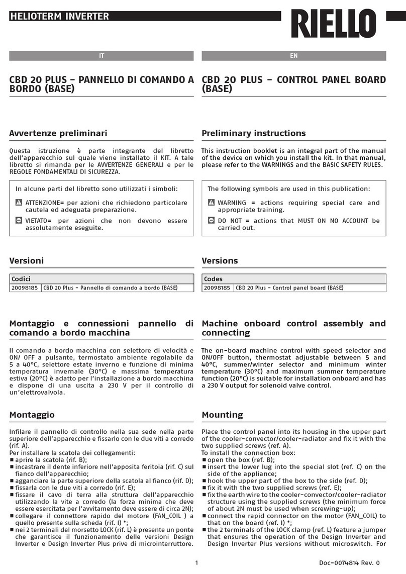
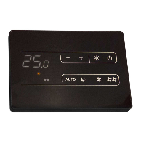
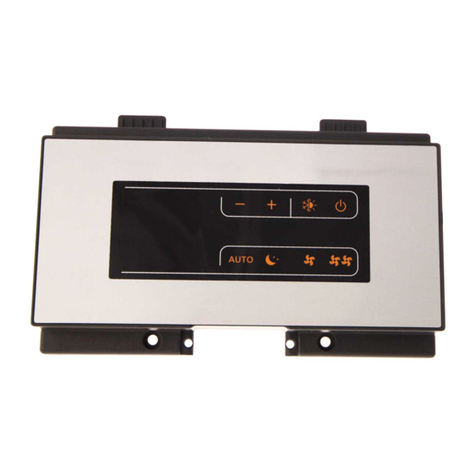
Riello 20081467 User manual

HYDROLINE
Cod. 20081969 Rev. 1
3
2
1
78
5
6
4
IT
1. Avvertenze preliminari
Questa istruzione è parte integrante del libretto
dell’apparecchio sul quale viene installato il KIT. A tale
libretto si rimanda per le AVVERTENZE GENERALI e per le
REGOLE FONDAMENTALI DI SICUREZZA.
COMANDO A BORDO PER IMPIANTI A 2
TUBI
2. Versioni
Codici
20081467 Comando Plus a bordo 2T
In alcune parti del libretto sono utilizzati i simboli:
ATTENZIONE= per azioni che richiedono particolare
cautela ed adeguata preparazione.
VIETATO= per azioni che non devono essere
assolutamente eseguite.
3. Composizione del kit
1 Comando 1
2 Viti + tasselli ad espansione 2
3 Istruzioni di installazione 1
4 Cavo collegamento (cablato) 1
5 Staffa fissaggio comando 1
6 Sensore aria 1
7 Viti 2
8 Mastice -
EN
1. Preliminary instructions
This instruction booklet is an integral part of the manual
of the device on which you install the kit. In that manual,
please refer to the WARNINGS and the BASIC SAFETY RULES.
BUILT IN CONTROL FOR 2 PIPES SYSTEM
2. Versions
Codes
20081467 2T Built-in Plus control panel
The following symbols are used in this publication:
WARNING = actions requiring special care and
appropriate training.
DO NOT = actions that MUST ON NO ACCOUNT be
carried out.
3. Kit composition
1 Control 1
2 Screws + Screw anchors 2
3 Installation instruction 1
4 Connecting cable (wired) 1
5 Metal plate to fix the control 1
6 Air sensor 1
7 Screws 2
8 Sealing material -

HYDROLINE
Cod. 20081969 Rev. 1
IT
Linea continua Cablaggio del costruttore
Linea tratteggiata Cablaggio dell’installatore
IFM Motore ventilatore
FC Condensatore motore ventilatore
EV Elettrovalvola
EC Contatto esterno
TB Morsettiera
CF/CM Connettori motore
CS Cambio stagionale remoto
* Opzionale
** Non usate
AS Sensore aria
WS Sensose acqua
A Marrone
B Blu
C Nero
R Rosso
W Bianco
O Arancio
V Viola
D Azzurro
Y Giallo
Y/G Giallo/verde
G Grigio
Aprire il comando rimuovendo la vite di sicurezza posta
lateralmente. Effettuare il collegamento del cavo in
dotazione come da figura allegata (3a) in funzione del
tipo di comando scelto.
Inserire il sensore di temperatura (rif.A) nell’apposito
connettore CN1, posizionare il ponticello JP1 come
indicato nella figura (2a).
Eseguire se necessario la configurazione dei ponticelli
PS (rif C).
Richiudere il comando con la vite di sicurezza tolta
precedentemente.
Togliere l’alimentazione elettrica.
Rimuovere il mobile.
Accedere alla parte superiore del quadro elettrico
posizionando il comando come da fig 1, inserendolo
nelle apposite linguette e bloccandolo con le due viti in
dotazione.
Aprire il quadro elettrico dell’unità ed effettuare i
collegamenti alla morsettiera come rappresentato nelle
figura (4a). Inserire i due connettori 4, 6 poli come
indicato nella figura 4A.
Infine fissare con il mastice in dotazione il sensore aria in
prossimità del ventilatore (vedi manuale di installazione
unità).
4. Comando a bordo macchina
EN
Continuous line Factory wiring
Dotted Line Wiring by others
IFM Fan motor
FC Fan motor capacitor
EV Solenoid valve
EC External contact
TB Terminal block
CF/CM Motor connector
CS Remote change over switch
* Optional
** Non usate
AS Air sensor
WS Water sensor
A Brown
B Blue
C Black
R Red
W White
O Orange
V Violet
D Light blue
Y Yellow
Y/G Yellow/Green
G Gray
Open the control by removing the side security screw.
Connect the cable supplied as shown in the attached
figure (3a) according to the type of control chosen.
Insert the temperature sensor (ref.A) into the
corresponding CN1connector, position the JP1 jumper as
shown in the figure (2a).
If necessary, configure the PS jumpers (ref C).
Close the control using the security screw which had
been removed before.
Disconnect the power supply.
Remove the cabinet.
Access the upper part of the electrical panel positioning
the control as shown in figure 1. It has to be inserted
in the dedicated tabs and secured with the two screws
provided.
Open the electrical panel of the unit to connect the
terminal box as shown in figures 4a and 4b. Insert the
two connectors with 4 or 6 poles as indicated in figure
4A.
Finally, secure the air sensor near the fan using the
sealing material provided (see the installation manual
of the unit).
4. Unit-mounted control

HYDROLINE
Cod. 20081969 Rev. 1
IT EN

HYDROLINE
Cod. 20081969 Rev. 1
W.CC.HEAT C.COOL NL HF MF LF VALE
CN2
CN1
1 2 3
P5P4P3P2P1
CN4
Fig. F1ig. 2 A
Fig. 3 FA ig. 4 A
VALE LF MF HF LN COOL HEAT W_C
JP1
123
A
TO ELECTRONIC CONTROL - AL COMANDO ELETTRONICO
C
IT EN

HYDROLINE
Cod. 20081969 Rev. 1
IT
Il comando viene utilizzato negli impianti a 2 tubi.
Il comando provvede a mantenere la temperatura
interna impostata dalla manopola tra 10°C e 30°C.
Tramite il pulsante di selezione della velocità del
ventilatore è possibile scegliere in modo manuale o
automatico la modalità di funzionamento del ventilatore.
In modalità manuale è possibile scegliere tre tipi di
velocità bassa/media/alta) in funzione delle necessità
oppure la modalità economica.
In modalità auto la velocità del ventilatore è regolata
dal microprocessore del comando in funzione della
temperatura scelta.
Durante l’installazione è tuttavia possibile selezionare
la ventilazione continua, agendo sui microinterruttori
presenti sulla scheda elettronica (vedere configurazione
ponticelli).
Mediante apposito sensore (optional) è possibile
escludere la ventilazione quando in modalità
riscaldamento la temperatura dell’acqua è inferiore a 35
°C e in modalità raffrescamento è superiore a 18°C.
Queste due funzioni permettono di ottenere un maggior
comfort durante il funzionamento invernale evitando
ventilazioni indesiderate, mentre in modalità estiva
consentono lo spegnimento e l’accensione in modo
automatico di tutti i ventilconvettori in funzione della
temperatura dell’acqua.
5. Funzioni
6. Ventilazione
1 Pulsante POWER
2 LED blu funzione raffrescamento
3 Pulsante FAN
4 LED rosso funzione riscaldamento
5 Pulsante MODE
6 LED verde funzione risparmio energetico
7 Manopola temperatura
8 LED giallo funzione selezione automatica della velocità
del ventilatore
9 LED rossi funzione velocità del ventilatore
EN
Control is used in 2-pipe systems.
Control have a knob to select the temperature, with
a range from 10°C to 30°C, and room temperature is
maintained at the selected value.
Use the speed selection button of the fan to select the
manual or automatic operating mode of the fan.
In manual mode, it is possible to select three fan speeds
(low/medium/high) according to the need, or the
economy mode.
In the auto mode fan speed is regulated by a
microprocessor in the control in relation to the
temperature chosen.
During installation, it is possible to select continuous
fan operation via the switch located on the electronic
board (see section dipswitch configuration).
As an option, fan operation can be disabled during
heating by means of a sensor if water temperature is
below 35°C, and during cooling if water temperature is
above 18°C.
These two functions allow improved comfort levels
during winter by avoiding undesired fan operation
and during summer by turning the fan coils on and off
automatically in relation to the water temperature.
5. Functions
6. Fan operation
1 POWER button
2 Blue LED - cooling operation
3 FAN button
4 Red LED - heating operation
5 MODE button
6 Green LED - energy saving operation
7 Temperature knob
8 Yellow LED - fan automatic speed selector
9 Red LEDs - fan speed operation

HYDROLINE
Cod. 20081969 Rev. 1
IT
La funzione antigelo permette di evitare in ambienti non
frequentati per lunghi periodi che la temperatura scenda
sotto 7°C.
Raggiunta questa temperatura il controllo provvede ad
attivare la valvola e il ventilatore alla alta velocità.
La funzione antigelo può essere attivata configurando il
relativo microinterruttore (vedi configurazione ponticelli);
se abilitata è attiva anche con comando in posizione OFF.
Questa funzione è particolarmente utile durante il
funzionamento notturno o negli ambienti climatizzati
nei quali si suppone di dover rimanere assenti per un
certo periodo di tempo. In questo caso selezionando la
funzione mediante ripetuta pressione del tasto FAN è
possibile aumentare di 4°C la temperatura impostata
durante il funzionamento in modalità raffrescamento e di
ridurre di 4°C la temperatura durante il funzionamento in
modalità riscaldamento. L’abilitazione di questa funzione
(LED verde inserito) esclude le altre visualizzazioni.
Manuale
La selezione riscaldamento/raffrescamento, viene effettuata
manualmente tramite il pulsante sul comando.
Centralizzato
Il cambio stagionale centralizzato può essere effettuato in due
modi:
tramite un deviatore posizionato nella centrale di comando
che permette di commutare la modalità riscaldamento/
raffrescamento;
tramite una sonda di tipo a contatto (Accessorio) da
posizionare sulla tubazione di ingresso dell’acqua.
In quest’ultima modalità, il funzionamento del ventilconvettore
viene pilotato dal comando in riscaldamento o in raffrescamento
a seconda della temperatura rilevata dal sensore.
Sia il deviatore che la sonda, funzionano con tensione di 230V,
per cui devono essere adeguatamente isolati. La pressione sul
tasto cambio stagionale manuale mentre è attivo il cambio
stagionale centralizzato provoca un breve lampeggio del LED
relativo alla modalità di funzionamento attiva.
Ad ogni modo il cambio stagionale centralizzato esclude il
funzionamento del cambio stagionale locale.
Il comando è dotato di un ingresso da utilizzare come
contatto finestra, o sensore di presenza (vedi schema
elettrico).
Quando tale segnale è abilitato (presenza del potenziale di
linea al contatto della morsettiera) il comando viene posto
in OFF (finestra aperta) o in Energy Saving (ambiente non
occupato), a secondo di come il comando è configurato. Nel
caso in cui il comando venga posto in OFF, la conseguenza
è che vengono disabilitate tutte le uscite (ventilatore,
valvole, etc.) e rimane attiva la sola funzione di antigelo se
abilitata dal relativo ponticello. Nel caso in cui il comando
venga posto in Energy Saving, la temperatura interna
viene aumentata di 4°C in raffrescamento e diminuita di
4°C in riscaldamento.
Il cambio di configurazione tra queste due possibilità di
funzionamento avviene mediante pressione continuativa,
per almeno 5 secondi, del tasto Power e del tasto di
7. Antigelo
8. “Energy saving” (risparmio energetico)
9. Cambio stagionale
10. Contatto esterno
EN
This function keeps the temperature from dropping below
7°C in rooms not used for long periods of time.
When this temperature is reached, the control activates
the valve and puts the fan on high speed.
The frost protection function can be activated through
the associated micro-switch (see section dip-switch
configuration); if enabled, this function activates even
when the control is in the OFF position.
This function is especially useful when air conditioning at
night or in rooms where the user is likely to be absent for
a longer period of time.
In this case, by selecting the function e and pressing the
FAN button repeatedly it is possible to raise the setpoint
temperature by 4°C in cooling mode and reduce it by 4°C in
heating mode.
Enabling this function (Green LED ON) cuts out other
displays.
Manual
Selection of heating/cooling is done manually by pushing
the button on the control.
Centralised
Centralised seasonal changeover can be done in two ways:
by a switch located on the central control panel that
allows heating/cooling mode changeover;
by a temperature sensor (Accessory) located in contact
with the entering water pipe.
In this last mode, fan coil operation is driven by the control,
in cooling or heating, depending on the temperature read
by the sensor.
Switch and sensor operate on 230V power supply, so both
must be adequately insulated.
If the seasonal manual changeover button is pushed
while the centralised changeover mode is activated, the
corresponding LED will briefly flash while maintaining the
activated mode.
In any case, centralised changeover takes priority over
local changeover.
The control has an input that can be used as window
contact or presence detection (see wiring diagram). When
such a signal is activated (presence of line voltage on the
terminal block contact) the control is set to OFF (open
window) or to Energy Saving (empty room), depending on
the control configuration.
If the control is set to OFF, as a consequence all outputs
are disconnected (fan, valves, etc.) and only the frost
protection function is active if it has been enabled by its
corresponding dip-switch. If the control is set to Energy
Saving, the internal temperature is raised by 4°C in cooling
mode and reduced by 4°C in heating mode.
To switch from one operating mode to the other, keep the
Power button and the speed selection button pressed for
at least 5 seconds.
7. Frost - protection
8. Energy saving
9. Seasonal changeover
10. External contact

HYDROLINE
Cod. 20081969 Rev. 1
IT
Dopo 10 secondi in cui tasti e manopola non vengono
toccati dall’utente, i LEDs affievoliscono l’intensità della
luce emessa, in modo da disturbare meno la vista. Questo
effetto è definito modalità “Notte”. Mediante apposita
selezione, c’è la possibilità di oscurare completamente la
luce dei LEDs (modalità “Oscuramento”).
La selezione della modalità “Oscuramento viene fatta
posizionando la velocità del ventilatore al massimo, e
tenendo premuto per 5 secondi il tasto di selezione della
velocità del ventilatore. La selezione viene indicata da 4
lampeggi del LED rosso che indica la massima velocità del
ventilatore.
Con analoga operazione si può tornare alla modalità
“Notte”. In questo la caso la selezione è accompagnata da
3 lampeggi del medesimo LED.
Permette di regolare la temperatura desiderata. Il valore
di riferimento a centro scala è di 20°C.
Ruotando la manopola verso il simbolo ( – ) si ha una
riduzione del valore della termperatura impostata (valore
minimo 10°C).
Ruotando la manopola verso il simbolo ( + ) si ha un
aumento del valore della temperatura impostata (valore
massimo 30°C).
POWER
Questo pulsante serve per accendere e per spegnere
il comando. Una volta spento, tutte le funzioni
sonodisabilitate ma il comando resta comunque
alimentato con 230V.
Se la funzione antigelo (frost-protection) viene selezionata
tramite l’apposito microinterruttore, questa diventa attiva
anche con comando spento.
MODE
Questo pulsante serve per cambiare manualmente
la modalità di funzionamento, da raffrescamento a
riscaldamento e viceversa.
FAN
Questo pulsante serve per selezionare manualmente la
velocità del ventilatore (bassa, media ed alta velocità).
Continuando a premere questo pulsante si può selezionare
la scelta automatica della velocità del ventilatore, gestita
dal microprocessore.
Se selezionata questa modalità di funzionamento, il LED
giallo è acceso. Inoltre, sempre con lo stesso pulsante si
può selezionare anche la modalità Energy Saving, in cui
la temperatura richiesta in ambiente viene aumentata di
4°C in raffrescamento, diminuita di 4°C in riscaldamento.
La modalità Energy Saving è accompagnata dall’accensione
del LED verde.
11. Modalità “Notte” e “Oscuramento”
13. Selettore temperatura
12. Funzione dei pulsanti
selezione della velocità.
Il cambio di configurazione è accompagnato da un segnale
luminoso, 3 lampeggi del LED verde per il passaggio da
configurazione OFF a Energy Saving e LED verde acceso per
3 secondi per il passaggio opposto.
EN
If the buttons and the knob are not pressed or used for
10 seconds, the light is dimmed by the LEDs to reduce the
disturbing light. This function is called “Night” mode. By
a special selection, the LEDs light can be fully darkened
(“Darkening” mode).
The “Darkening” mode can be selected by setting the fan
speed to its maximum value and keeping the selection
button of fan speed pressed for 5 seconds. 4 flashes of the
red LED indicate the fan maximum speed.
With the same operation it is possible to return to “Night”
mode.
In this case, the same LED is flashing 3 times.
POWER
This button is used to turn the control on and off. When it
is OFF, all functions are disconnected but the control is still
powered at 230V.
If the frost protection function is selected by the special
microswitch, this function is activated even if the control
is off.
MODE
This button is used to manually switch from cooling to
heating mode and vice versa.
FAN
this button is used to select the fan speed manually (low,
medium and high speed).
Keep on pressing this button to select the automatic fan
speed selection, which is controlled by the microprocessor.
If this operating mode is selected, the yellow LED is on.
Moreover, by using the same button it is possible to select
the Energy Saving function where the room temperature
required is raised by 4°C in cooling mode and reduced by
4°C in heating mode. The green LED turns on when the
Energy Saving mode is active.
Its purpose is to maintain the temperature at the desired
level. The reference value at the centre of the range is 20°C.
By turning the knob towards the symbol ( – ) the
temperature is reduced from the original setting (minimum
value is 10°C).
By turning the knob towards the symbol ( + ), the
temperature is raised from the original setting (maximum
value is 30°C).
11. “Night” and “Darkening” mode
12. Button operation
13. Temperature selector
The switching from one configuration to the other is
signalled by a light. The Green LED flashes 3 times when
switching from OFF to Energy Saving and the same green
LED remains ON for 3 seconds when switching from Energy
Saving to OFF.

HYDROLINE
Cod. 20081969 Rev. 1
IT
LED blu
Acceso Indica che il comando è in modalità
raffrescamento ( ).
Lampeggiante Indica che il comando è in modalità
antigelo ( ).
LED rosso (gruppo di destra)
Acceso Indica che il comando è in modalità
riscaldamento ( ).
Lampeggiante Indica la presenza di una anomalia (sonda
interrotta).
LED rossi (gruppo di sinistra)
Acceso Indica che il ventilatore sta funzionando
alla velocità selezionata.
LED giallo
Acceso Indica che la selezione della velocità dei
ventilatori è determinata automaticamente
().
LED verde
Acceso Indica che il comando è in modalità Energy
Saving (risparmio energetico) ( ).
Lampeggiante Indica che il comando è in modalità OFF
forzato dal contatto esterno.
LED rosso / blu
Lampeggiante Indicano che il comando è in modalità
“Autotest”.
Ponticello n° 1 (P1)
In posizione di contatto aperto permette l’attivazione
della funzione antigelo ( ).
Ponticello n° 2 (P2)
In posizione di contatto aperto consente il funzionamento
del ventilatore alla velocità selezionata anche quando è
stata raggiunta le temperatura di set-point.
Ponticello n° 3 (P3)
In posizione di contatto aperto limita il campo di
regolazione della manopola temperatura secondo i
seguenti limiti:
Raffrescamento: temperatura minima selezionabile: 23°C.
Riscaldamento: temperatura massima selezionabile: 21°C.
Ponticello n° 4 (P4)
In posizione di contatto aperto consente di attivare il
ventilatore ad intervalli regolari di tempo anche quando è
stata raggiunta la temperatura di set-point (Air sampling).
14. Indicazioni luminose
15. Funzioni “ponticelli” (microinterruttori)
EN
Blue LED
ON
Indicates that the control is in cooling mode ( ).
Flashing Indicates that the control is in frost protection
mode ( ).
Red LED (group on the right)
ON
Indicates that the control is in heating mode ( ).
Flashing Indicates the presence of a fault (sensor failed
or not connected)
Red LEDs (group on the left)
ON Indicates that the fan is operating at the
selected speed.
Yellow LED
ON Indicates that the selection of the fan speed is
set automatically
( )
.
Green LED
ON Indicates that the control is in Energy Saving
mode ( ).
Flashing Indicates that the control is in O FF mode forced
by the external contact.
Red / Blue LED
Flashing Indicates that the control is in “Autotest” mode.
Dip-switch no. n° 1 (P1)
In open contact position, it allows to activate the frost
protection function ( ).
Dip-switch 2 (P2)
In open contact position, it permits the fan operation at
the selected speed even if the set point temperature is
satisfied.
Dip-switch 3 (P3)
In open contact position, it restricts the range of the
temperature selection knob according to the following
limits:
Cooling: minimum selectable temperature: 23°C.
Heating: maximum selectable temperature: 21°C.
Dip-switch 4 (P4)
In open contact position, it permits to activate the fan
periodically even if the set point temperature is satisfied
(air sampling).
14. Light indicators
15. “Dip-switch” function (microswitches)

HYDROLINE
Cod. 20081969 Rev. 1
IT
Ponticello 1 (P1)
Chiuso Antigelo ( ) disabilitato.
Aperto Antigelo ( ) abilitato.
Ponticello 2 (P2)
Chiuso Ventilazione controllata dal termostato.
Aperto Ventilazione continua.
Ponticello 3 (P3)
Chiuso Blocco temperature disattivato.
Aperto Blocco temperature attivato.
Ponticello 4 (P4)
Chiuso “Air Sampling” disattivato.
Aperto “Air Sampling” attivato.
La configurazione di fabbrica è con tutti i ponticelli in
posizione di chiuso.
Sensore Interno
E’ utilizzato in tutte le installazioni in cui il comando è montato
a parete. Per attivarlo, chiudere il jumper JP1 come indicato
nella figura A e sulla serigrafia della scheda elettronica.
Sensore Remoto
E’ utilizzato in tutte le installazioni in cui il comando è
installato sull’unità. E’ posizionato sul ritorno dell’aria, in
prossimità del ventilatore. Per attivarlo, chiudere il jumper JP1
come indicato nella figura 2A e sulla serigrafia della scheda
elettronica.
Per configurazione di fabbrica il sensore attivo è il
sensore interno.
Vengono evidenziate le seguenti situazioni di allarme:
Sensori difettosi: il LED rosso lampeggia.
Possibili cause:
sensore interno interrotto o in corto circuito;
sensore temperatura acqua interrotto o in corto circuito.
Il LED verde lampeggia ad intervalli di 0,25 secondi.
Tale situazione si verifica quando:
nel comando entrambi i segnali di cambio stagionale
centralizzato “RC e RH” sono abilitati.
16. Configurazioni“ponticelli”(microinterruttori)
17. Utilizzo del sensore di temperatura
18. Segnalazioni diagnostiche
19. Errata configurazione
EN
Dip-switch 1 (P1)
Closed Frost protection ( ) disabled.
Open Frost protection ( ) enabled.
Dip-switch 2 (P2)
Closed Ventilation controlled by thermostat.
Open Continuous ventilation.
Dip-switch 3 (P3)
Closed Temperature block disabled.
Open Temperature block enabled.
Dip-switch 4 (P4)
Closed “Air sampling” disabled.
Open “Air sampling” enabled.
Factory setting is with all dip-switches in close position.
Internal sensor
This is used in all installations where the control is wall-
mounted. To activate it, close jumper JP1 as shown in
figure A and on the electronic board screenprint.
Remote sensor
This is used on all installations with unitmounted control.
It is positioned on the return air, close to the fan. To
activate it, close jumper JP1 as shown in figure 2A and on
the electronic board screenprint.
Factory setting is with activated internal sensor.
The following alarm situations are indicated:
Defective sensors: the red LED flashes.
Possible causes:
failure or short circuit of internal sensor;
failure or short circuit of water temperature sensor.
The green LED flashes every 0.25 seconds.
This happens when:
in control, both centralised seasonal changeover signals
“RC and RH” are enabled.
16. “Dip-switch” configuration (microswitches)
17. Use of temperature sensor
18. Diagnostic warnings
19. Incorrect configuration

HYDROLINE
Cod. 20081969 Rev. 1
IT
La funzione “Autotest” viene attivata tenendo premuto
il pulsante cambio stagionale e contemporaneamente
premendo per tre volte il tasto di selezione delle velocità
entro 1 secondo.
In questo modo è possibile verificare l’accensione di tutte
le utenze.
Il LED blu e il LED rosso iniziano a lampeggiare. Le varie
utenze saranno attivate per 10 secondi ciascuna, nel
seguente modo:
bassa velocità ventilatore.
media velocità ventilatore.
alta velocità ventilatore.
CV elettrovalvola acqua fredda.
20.Autotest
EN
The “Autotest” function is activated by holding the
seasonal changeover button pressed and at the same time
pressing the speed selection button three times within 1
second.
In this way it is possible to check the starting of all fan
coils.
The blue and red LEDs will begin to flash.
Each of the various units will be activated for 10 seconds in
the following sequence:
Low fan speed.
Medium fan speed.
High fan speed.
CV Motorized cold-water valve.
20.Autotest

HYDROLINE
Cod. 20081969 Rev. 1
IT EN

HYDROLINE
Cod. 20081969 Rev. 1
RIELLO S.p.A. - 37045 Legnago (VR)
tel. +39 0442 630111 - fax +39 0442 22378
www.riello.it
Poiché l’Azienda è costantemente impegnata nel continuo perfezionamento di tutta la sua produzione, le
caratteristiche estetiche e dimensionali, i dati tecnici, gli equipaggiamenti e gli accessori, possono essere soggetti
a variazione.
As the manufacturer is constantly improving its products, the aesthetic or dimensional features, the technical data,
the equipment and accessories indicated could be subject to variations.
L010130H92
Other manuals for 20081467
1
Table of contents
Other Riello Control Panel manuals

Riello
Riello Touchscreen N User manual

Riello
Riello CBD 35 User manual

Riello
Riello 4030011 User manual

Riello
Riello CPD 30 User manual

Riello
Riello CBD 35 User manual

Riello
Riello NexSirius User manual

Riello
Riello Wired Touch panel User manual

Riello
Riello 20147241 User manual

Riello
Riello Thermital TBOX BASIC ACS Technical manual

Riello
Riello RIELLOtech CLIMA TOP User manual