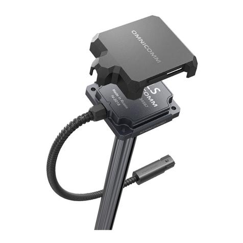
SEA SUNSET User manual

BARRIERA FOTOELETTRICA SUNSET
(cod. 23102076)
SEA S.p.A.
DIREZIONE E STABILIMENTO:
Zona industriale 64020 S.ATTO Teramo - (ITALY)
Tel. +39 0861 588341 r.a. Fax +39 0861 588344
http://www.seateam.com
e-mail:[email protected]
Rev. 06 - 05/2013 Pag. 1
IT Italiano
Generalità
La barriera fotoelettrica SUNSET è stata progettata per applicazioni in cui è necessario applicare due
fotocellule sovrapposte, senza che le stesse vadano in collisione tra loro. Per ottenere tale risultato basta
alimentare le fotocellule con alimentazione 12/24 V~ e incrociare le alimentazioni. (Es. Se TX e RX di una
fotocellula sono alimentati con un cavo di colore nero sullo 0 V~ e con un cavo di colore rosso sulla 24V~, TX e
RX dell’altra fotocellula dovranno avere il cavo di colore rosso sullo 0 V~ e il cavo di colore nero sulla 24 V~).
Contenuto della confezione del dispositivo:
N° 1 Fotocellula ricevitore
N° 1 Fotocellula trasmettitore
N° 1 KIT per il fissaggio
N° 2 Tappi coprivite
N° 1 Foglio istruzioni per l'installatore.
Caratteristiche tecniche
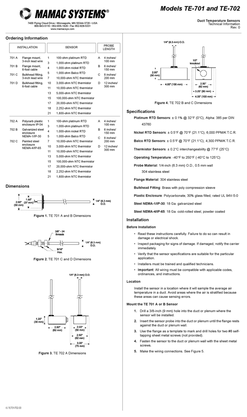
Portata: 15 m in esterno
Segnale: infrarosso modulato
Lunghezza d'onda: 880nm
Frequenza di modulazione: 1000Hz
Alimentazione: 12 - 24 V / V~
Assorbimento: 30mA TX; 30mA RX
Temperatura di funzionamento: -15°C / +60°C
Portata contatti relè: 1A max @24V
Umidità: dal 5% al 90% non condensante
Nota bene: Per avere la funzione sincronizzata, l’alimentazione deve essere necessariamente in 12/ 24
V~.
Sistemi Elettronici
di Apertura Porte e Cancelli
International registered trademark n. 804888
®
Fig. 1
JP1 ON = SINCRONIZZAZIONE ATTIVA
JP1 OFF = SINCRONIZZAZIONE NON ATTIVA
40
42
40
42
JP1JP1
JP1JP1
Fig.2
1 2 3
1 2 3 4 5 6
NONO
COMCOM
NCNC
+12+12
+12+12 +24+24
+24+24 00
00
Tx1 Rx1
Fig. 1
1 2 3
1 2 3 4 5 6
NONO
COMCOM
NCNC
+12+12
+12+12 +24+24
+24+24 00
00
Tx2 Rx2
40
42
40
42
JP1JP1
JP1JP1
21 mm
30 mm
55 mm
Cod. 67410885
INSTALLAZIONE
Trasmettitore
- Infilare i cavi nell'apposita sede ed effettuare i collegamenti in base
al tipo di applicazione, 12 o 24V~ o V , sincronizzata o non
sincronizzata.
- Assestare i cavi in modo da eliminare l'eccedenza.
- Fissare il Trasmettitore.
- Sigillare la guaina ed eventuali fori che possano convogliare
all'interno del contenitore corpi estranei.
Ricevitore
- Infilare i cavi nell'apposita sede ed effettuare i collegamenti in base
al tipo di applicazione scelta per il trasmettitore, 12/24V~ o V ,
sincronizzata o non sincronizzata .
- Assestare i cavi in modo da eliminare l'eccedenza.
- Fissare il Ricevitore, avendo cura di fissarlo in posizione frontale,
allineato sullo stesso asse e alla stessa altezza del Trasmettitore
associato.
- Sigillare la guaina ed eventuali fori che possano convogliare
all'interno del contenitore corpi estranei.
Una volta eseguite le precedenti operazioni sia per Tx che per Rx:
- Alimentare le fotocellule 12-24V~ o V e verificarne
l’allineamento. Se il posizionamento, l'allineamento ed il
collegamento della fotocellula sono eseguiti correttamente, il LED
rosso sul ricevitore sarà acceso.

Operazioni di verifica
Interrompere più volte il raggio infrarosso con un cartoncino nero (o comunque opaco all'infrarosso)
verificando:
- la risposta (scambio) del relè
- ogniqualvolta si interrompe il raggio, il LED rosso sul ricevitore si spegne.
Funzionamento del LED rosso:
LED ROSSOACCESO: dispositivo 23102076ALLINEATO
LED ROSSO SPENTO: dispositivo 23102076 NONALLINEATO
SICUREZZE
Il dispositivo 23102076 non può essere utilizzato come dispositivo di sicurezza (EN 12978).
RICAMBI
Le richieste per parti di ricambio devono pervenire presso:
SEAS.p.A. - Zona Ind.le, 64020 S.ATTO - Teramo - Italia
DESTINAZIONE D'USO
La fotocellula 23102076 è stata progettata per essere utilizzata esclusivamente come barriera fotoelettrica da
disporre nelle zone considerate di pericolo ed in prossimità del cancello/anta, essa dev'essere utilizzata per
funzionare esclusivamente per interposizione fra trasmettitore e ricevitore (installati secondo le suindicate
istruzioni) e dev'essere alimentata a tensione di sicurezza.
SICUREZZAE COMPATIBILITÀAMBIENTALE
Si raccomanda di non disperdere nell'ambiente i materiali di imballaggio del prodotto e/o circuiti.
REQUISITI DI CONFORMITÀ
La fotocellula 23102076 è conforme alle seguenti norme:
2004/108/CE (Direttiva sulla Compatibilità Elettromagnetica)
IMMAGAZZINAMENTO
La movimentazione del prodotto deve essere seguita con mezzi idonei.
PULIZIAE MANUTENZIONE
Gli interventi di pulizia e manutenzione devono essere implementati solo ed esclusivamente da personale
autorizzato ed esperto con cadenza almeno semestrale curando di verificare: il corretto allineamento fra
trasmettitore e ricevitore, la tenuta dei sistemi di fissaggio, la pulizia della lente ricavata sul frontalino, la pulizia
delle parti interne al contenitore e quant'altro ritenuto necessario al corretto funzionamento del dispositivo.
MESSAFUORI SERVIZIO E MANUTENZIONE
La disinstallazione e/o messa fuori servizio del dispositivo 23102076 dev'essere eseguita solo ed
esclusivamente da personale autorizzato ed esperto.
LIMITI DI GARANZIA
Per la garanzia vedere le Condizioni di vendita riportate nel Listino ufficiale Sea.
N.B. IL COSTRUTTORE NON PUÒ CONSIDERARSI RESPONSABILE PER EVENTUALI DANNI
CAUSATI DA USI IMPROPRI, ERRONEI ED IRRAGIONEVOLI.
La SEA si riserva il diritto di apportare le modifiche o variazioni che ritenesse opportune ai propri prodotti e/o al
presente manuale senza alcun obbligo di preavviso.
TEMPERATURE DI STOCCAGGIO
Tmin TMax Umiditàmin UmiditàMax
- 20°C + 70°C 5% non condensante 90% non condensante
Italiano
http://www.seateam.com
e-mail:[email protected]
Pag. 2
Cod. 67410885 Rev. 06 - 05/2013
SEA S.p.A.
DIREZIONE E STABILIMENTO:
Zona industriale 64020 S.ATTO Teramo - (ITALY)
Tel. +39 0861 588341 r.a. Fax +39 0861 588344
Sistemi Elettronici
di Apertura Porte e Cancelli
International registered trademark n. 804888
®

INFRARED BEAM PHOTOCELL SUNSET
(cod. 23102076)
http://www.seateam.com
e-mail:[email protected]
Pag. 3
GB English
General
The photoelectric barrier SUNSET has been projected for applications in which it is necessary to apply two
overlapping photocells, avoiding that they go in collision one with the other. To get such result it is sufficiant to
power supply the photocells with 12/24 V~ and to cross the power supply. (Ex. When the TX and RX of a
photocell are power supplied with a black cable around 0 V~ and with a red cable of 24V~, the TX and the RX
of the other photocell will have to have the red cable with 0 V~ and the black cable around 24 V~.)
The Photocell Kit Consists of:
1 No. Photocell Receiver
1 No. Photocell Transmitter
1 No. Fixing Kit
2 No. cover-screw cap
1 No. Set of fitting instructions
Technical Characteristics
Range: 15 m (exterior use)
Signal: Modulated infrared
Wave length: 880 nm
Modulation Frequency: 1000 Hz
Supply Voltage: 12 - 24 V / V~
Absorbed Current: 30mA TX; 30mA RX
Temp. Operating Range: -15° C / +60° C
Relay Contact Rating: 1A max; 24V
Humidity: from 5% to 90% no
condensation
Please note: For the syncronized function, the power supply has to be necessarily of 12/24 V~.
Sistemi Elettronici
di Apertura Porte e Cancelli
International registered trademark n. 804888
®
Fig. 1
40
42
40
42
JP1JP1
JP1JP1
Fig.2
1 2 3
1 2 3 4 5 6
NONO
COMCOM
NCNC
+12+12
+12+12 +24+24
+24+24 00
00
Tx1 Rx1
Fig. 1
1 2 3
1 2 3 4 5 6
NONO
COMCOM
NCNC
+12+12
+12+12 +24+24
+24+24 00
00
Tx2 Rx2
40
42
40
42
JP1JP1
JP1JP1
21 mm
30 mm
55 mm
Cod. 67410885
JP1 ON = SYNCRONIZATION ACTIVATED
JP1 OFF = SYNCRONIZATION NOT ACTIVATED
INSTALLATION
Transmitter
-Insert the cables in the special seat and make the connections
according to the type of application, 12 or 24V~ or V ,
synchronized or not synchronized.
-Adjust the cable within the unit to eliminate any surplus.
-Fix the unit.
-Seal the cover & cable entry to prevent insect infestation.
Receiver
-Insert the cables into the special seat and make the connections
accoriding to the type of application chosen for the transmitter, 12/
24V~ or V , synchronized or not synchronized.
-Adjust the cable within the unit to eliminate any surplus.
-Make sure that the receiver is in frontal position, lined up on the
same axis and in the same height of the associated transmitter.
-Seal the cover & cable entry to prevent insect infestation.
Once executed the preceding operations for both Tx and for Rx:
-Power supply the photocells 12-24V~ or V and verify their
alignment. If the positioning, the alignment and the connection of
the photocells are correct, the red LED on the receiver will be
switched on.
Rev. 06 - 05/2013
SEA S.p.A.
DIREZIONE E STABILIMENTO:
Zona industriale 64020 S.ATTO Teramo - (ITALY)
Tel. +39 0861 588341 r.a. Fax +39 0861 588344

http://www.seateam.com
e-mail:[email protected]
Pag. 4
Operational Verification
Fit one of the black plastic photocell covers complete with an opaque diffuser label stuck across the lens.
- Check that the relay works correctly.
- Check that the red led goes out when the beam is broken.
Red led Function:
RED LED LIT: CORRECTLYALIGNED. NORMAL QUIESCENT STATE.
RED LED UNLIT: INCORRECTLYALIGNED OR BEAM INTERRUPTED.
SPARE PARTS
To obtain spare parts contact:
SEA - Zona Ind.le, 64020 S.ATTO - Teramo - Italia.
INTENDED USE
ENVIRONMENT
Please dispose of this product packaging in a responsible, appropriate way.
CONFORMITIES
The photocell conforms to the following:
2004/108/CE (Act on the Electromagnetic Compatibility)
STORING
When being transported this product must be properly packaged and handled with care
CLEANINGAND MAINTENANCE
Cleaning and maintenance of this unit must be carried out at 6 monthly intervals by authorised, qualified
personnel. During routine maintenance the following checks should be made: Correct alignment, sealing,
cleanliness of the lenses and internal components.Any remedial work should be carried out as required.
DECOMMISSIONING
If the photocell is to be taken out of service, this work must only be undertaken by authorised,
qualified personnel.
LIMIT OF GUARANTEE
For the guarantee see the sales conditions on the official SEAprice list.
NOTE: THE MANUFACTURER CAN NOT BE DEEMED RESPONSIBLE FOR ANY DAMAGE OR INJURY
CAUSED BY IMPROPER USE OF THIS PRODUCT.
SEA reserves the right to do changes or variations that may be necessary to its products with no obligation to
notice.
SECURITY
The 23102076 device cannot be used as security device (EN 12978).
The photocell 23102076 has been projected to be used exclusivley as photoelectric barrier to be installed in
the areas considered dangerous and in proximity of the gate/ leaf, it must be used exclusively for the
functioning as interposition between transmitter and receiver (installed according to the above mentioned
instructions) and must be power supplied with safety tension.
23102076
23102076
S.p.A.
STORAGE TEMPERATURES
Tmin Tmax Humiditymin Humiditymax
-20 °C +70 °C 5% no condensation 90% no condensation
English
Sistemi Elettronici
di Apertura Porte e Cancelli
International registered trademark n. 804888
®
Cod. 67410885 Rev. 06 - 05/2013
SEA S.p.A.
DIREZIONE E STABILIMENTO:
Zona industriale 64020 S.ATTO Teramo - (ITALY)
Tel. +39 0861 588341 r.a. Fax +39 0861 588344

BARRIERE INFRAROUGE SUNSET
(cod. 23102076)
http://www.seateam.com
e-mail:[email protected]
Pag. 5
FR
Generalites
La barrière photoélectrique SUNSET a été projeté pour applications dans lesquelles il est nécessaire
d'appliquer deux fotocellules superposées, sans que les mêmes aillent en collision entre eux. Pour obtenir tel
résultat il suffit d'alimenter les photocellules avec une alimentation à 12/24 V~ et de croiser les alimentations.
(Ex. Si TX et RX d'une photocellule sont alimentés avec un câble de couleur noire de 0 V~ et avec un câble de
couleur rouge de 24V~, le TX et RX de l'autre photocellule devront avoir le câble de couleur rouge à 0 V~ et le
câble de couleur noire à 24 V~.
L'ensemble comprend les éléments suivants:
N. 1 cellule photo-éléctrique réceptrice
N. 1 cellule photo-éléctrique émettrice
N. 1 kit pour la fixation
N. 2 bouchon couvre-vis
N. 1 Mode d'emploi
ATTENTION: Pour avoir la fonction synchronisée, l'alimentation doit être nécessairement de 12 / 24 V~.
Sistemi Elettronici
di Apertura Porte e Cancelli
International registered trademark n. 804888
®
Français
Caracteristiques techniques
Portée: 15 m. nominale à l'éxterieur
Signal: infrarouge modulé
Longueur d'onde: 880 nm
Fréquence infrarouge: 1000 Hz
Alimentation: 12 - 24 V / V~
Absorption: 30 mA TX; 30 mA RX
Temp. de fonction.: - 15 °C / + 60 °C
Portée contacts relais: 1A max ; 24V
Humidité: de 5 % à 90 % sans condensation
Fig. 1
40
42
40
42
JP1JP1
JP1JP1
Fig.2
1 2 3
1 2 3 4 5 6
NONO
COMCOM
NCNC
+12+12
+12+12 +24+24
+24+24 00
00
Tx1 Rx1
Fig. 1
1 2 3
1 2 3 4 5 6
NONO
COMCOM
NCNC
+12+12
+12+12 +24+24
+24+24 00
00
Tx2 Rx2
40
42
40
42
JP1JP1
JP1JP1
21 mm
30 mm
55 mm
Cod. 67410885
JP1 ON = SYNCHRONISATION ACTIVE
JP1 OFF = SYNCHRONISATION PAS ACTIVE
INSTALLATION
Cellule photo-éléctrique émettrice
-Enfiler les câbles dans le siège spécial et effectuer les liaisons selon le
type d'application (12 ou 24V~ou V ) synchronisée ou ne pas
synchronisée.
-Remettre en place les câbles de sorte que l'excédent soit éliminée.
-Fixer ou emboîter le transmetteur.
- Fermer hérmetiquement la gaine et eventuels trous qui pourraient
acheminer des corps étrangers à l’interieur du récipient.
Cellule photo-éléctrique réceptrice
-Enfiler les câbles dans le siège spécial et effectuer les liaisons selon le
type d'application choisi pour le transmetteur (12 / 24V~ ou V ,)
synchronisée ou ne pas synchronisée.
-Remettre en place les câbles de sorte que l'excédent soit éliminée.
-Fixer le Récepteur, en ayant soin de le fixer en position frontale, aligné
sur le même axe et à la même hauteur du Transmetteur associé.
-Fermer hérmetiquement la gaine et eventuels trous qui pourraient
acheminer des corps étrangers à l’interieur du récipient.
Une fois éxecutées les operations précédentes soit pour le RX soit pour
le TX:
-Alimenter les cellules photo-éléctriques 12 - 24 V~ ou V .
Si le positionnement, l'alignement et la liaison de la photocellule sont
exécutés correctement, le LED rouge sur le récepteur sera allumé.
Rev. 06 - 05/2013
SEA S.p.A.
DIREZIONE E STABILIMENTO:
Zona industriale 64020 S.ATTO Teramo - (ITALY)
Tel. +39 0861 588341 r.a. Fax +39 0861 588344

http://www.seateam.com
e-mail:[email protected]
Pag. 6
Opérations de contrôle
- la risposta (scambio) del relè
- chaque fois que le rayon est interrompu, le LED rouge doit s'éteindre.
Fonctionnement du LED rouge
LED ROUGEALLUME: ALIGNE
LED ROUGE ETEINT: NONALIGNE
PIECES DE RECHANGE
Les demandes de pièces de rechange sont à adresser à:
SEA Zona Ind.le, 64020 S.ATTO Teramo Italia.
UTILISATION
Le dispositif a été étudié pour l'utilisation exclusive comme barrière infrarouge à disposer dans les
zones dangereuses et en proximité du portail/vantail; l'utilisation de cette barrière est prevue exclusivement
comme interposition parmi l'émetteur et le récepteur (installés selon les instructions précédentes) et son
alimentation doit être à une tension de sécurité.
SECURITE ET COMPATIBILITE DE L'ENVIRONNEMENT
Ne pas disperser dans l'environnement les materiaux de l'emballage et/ou les circuits.
CONFORMITE
Le dispositif est conforme aux normes
2004/108/CE (Directive sur la compatibilité électromagnetique)
STOCKAGE
Le produit doit être mouvementé au moyens appropriés.
NETTOYAGE ET MAINTENANCE
Les interventions de nettoyage et maintenance doivent être réalisées seulement et exclusivement par
personnel autorisé et expert chaque six mois en vérifiant: l'alignement parmi l'émetteur et le récepteur, la tenue
des systèmes de fixation, le nettoyage de la lentille sue le frontal, le nettoyage des parties intérieures du
récipient et tous ce qu'il faut pour un correct fonctionnement du dispositif.
MISE HORS SERVICE
La désinstallation et/ou la mise hors service du dispositif doivent être réalisées seulement et
exclusivement par personnel autorisè et expert.
LIMITES DE LAGARANTIE
Pour la garantie voir les Conditions de Vente reportées dans la liste de prix officielle SEA.
N.B. LE CONSTRUCTEUR N'EST PAS RESPONSABLE DE DOMMAGES EVENTUELS A LA SUITE
D'UNE UTILISATION IMPROPRE, ERRONNEE OU IRRAISONABLE.
SEA se réserve le droit de faire des modifications ou des variations s'elle retient opportun pour ses produits
et/ou pour le présent manuel sans aucune obligation de préavis
Contrôler plusiers fois, en interrompant le faisceau infrarouge au moyen d'un carton noir (ou de toute façon
opaque à l'infrarouge) :
SECURITES
Le dispositif 23102076 ne peut pas être utilisé comme dispositif de sécurité (EN 12978).
23102076
23102076
23102076
S.p.A.
TEMPERATURES DE STOCKAGE
Tmin TMax Humiditémin HumiditéMax
- 20°C + 70°C 5% sans condensation 90% sans condensation
Français
Sistemi Elettronici
di Apertura Porte e Cancelli
International registered trademark n. 804888
®
Cod. 67410885 Rev. 06 - 05/2013
SEA S.p.A.
DIREZIONE E STABILIMENTO:
Zona industriale 64020 S.ATTO Teramo - (ITALY)
Tel. +39 0861 588341 r.a. Fax +39 0861 588344

BARRERA FOTOELECTRICA SUNSET
(cod. 23102076)
http://www.seateam.com
e-mail:[email protected]
Pag. 7
ES
Generalidades
~
~~
~~
La barrera fotoeléctrica SUNSET ha sido proyectada para aplicaciones dondes sea necesario instalar dos
fotocélulas sobrepuestas, sin que las mismas hagan intrerferencia entre ellas. Para obterner esta función, es
necesario alimentar las fotocélulas con tensión 12/24V y cruzar las alimentaciones. (Ej. si TX y RX de una
fotocélula son alimentados por un cable de color negro sobre lo 0 V y por un cable de color rojo sobre la 24V ,
TX y RX de la otra fotocélula deberán tener el cable rojo sobre lo 0 V y el cable negro sobre la 24 V ).
45
NOTA: para que la función sincronizada se pueda realizar, la tensión de alimetación debe necesariamente ser
de 12/24 V .~
Sistemi Elettronici
di Apertura Porte e Cancelli
International registered trademark n. 804888
®
Español
Contenido de la confeción:
N° 1 Fotocélula receptor
N° 1 Fotocélula tranmisor
N° 1 KIT para la fijación
N° 2 Tapon cubre-tornillo
N° 1 Folio de instrucciones para el instalador.
Caracteristicas tecnicas
Capacidad: 15 mts. en exterior
Señal: Infrarrojo modulado
Longitud de onda: 880nm
Frecuencia de modulación: 1000Hz
Alimentación: 12 - 24 V / V~ RX
Intensidad: 30mA TX; 30mA RX
Temperatura de funcionamiento: -15°C / +60°C
Capacidad contactos reles: 1A max ; 24V
Humedad: del 5% al 90% no condensable
Fig. 1
40
42
40
42
JP1JP1
JP1JP1
Fig.2
1 2 3
1 2 3 4 5 6
NONO
COMCOM
NCNC
+12+12
+12+12 +24+24
+24+24 00
00
Tx1 Rx1
Fig. 1
1 2 3
1 2 3 4 5 6
NONO
COMCOM
NCNC
+12+12
+12+12 +24+24
+24+24 00
00
Tx2 Rx2
40
42
40
42
JP1JP1
JP1JP1
21 mm
30 mm
55 mm
Cod. 67410885
JP1 ON= SINCRONIZACIÓN ACTIVA
JP1 OFF= SINCRONIZACIÓN NO ACTIVA
Guarnición
Base Tornillo
de fijación
Circuito
electrónico
Tornillo de
fijación tapa
Tapones
Cubretornillo
Tornillo de
fijación tapa
Tapa
Tornillo
de fijación
Guarnición
Guarnición
INSTALACION
Transmisor
- Inserir los cables en las correspondientes entradas y efectuar las
conexiones según el tipo de aplicación, 12/24 V o V , sincronizada
o no sincronizada.
- Acomodar los cables en modo de evitar el exceso.
- Fijar el Transmisor.
- Sellar la vaina a eventuales orificios que puedan llevar al interior del
contenedor cuerpos extraños.
Receptor
- Inserir los cables en las correspondientes entradas y efectuar las
conexiones según el tipo de aplicación, 12/24 V o V , sincronizada
o no sincronizada.
- Acomodar los cables en modo de evitar el exceso.
- Fijar el Receptor, tenendo cuidado de fijarlo en posición frontal, en
alineación sobre el mismo eje y a la misma altura del Emisor asociado.
- Sellar la vaina a eventuales orificios que puedan llevar al interior del
contenedor cuerpos extraños.
Una vez realizadas las precedentes operaciones sea para el TX como
para RX
- Alimentar la fotocélula 12-24 V o V y verificar la alineación. Si la
colocación, la alineación y la conexión de las fotocélulas han sido
realizadas correctamente, el LED rojo sobre el receptor se encenderá.
~
~
~
Rev. 06 - 05/2013
SEA S.p.A.
DIREZIONE E STABILIMENTO:
Zona industriale 64020 S.ATTO Teramo - (ITALY)
Tel. +39 0861 588341 r.a. Fax +39 0861 588344

http://www.seateam.com
e-mail:[email protected]
Pag. 8
Español
Sistemi Elettronici
di Apertura Porte e Cancelli
International registered trademark n. 804888
®
Operaciones de verificación
Interrumpir más veces el rayo infrarrojo con un cartoncito negro (o en cualquier caso opaco al infrarrojo)
verificando:
- La respuesta (cambio) del relé
- En cada caso si se interrumpe el rayo, el LED rojo sobre el receptor se apaga.
Funcionamiento del LED rojo:
LED ROJO ENCENDIDO: ALINEADO
LED ROJOAPAGADO: NOALINEADO
REPUESTOS
La solicitud de recambios debe realizarse a:
SEA Zona Ind.le, 64020 S.ATTO Teramo Italia
DESTINACION DE USO
El dispositivo ha sido proyectado para ser utilizado exclusivamente como barrera fotoeléctrica a
disponer en la zona considerada de peligro y en proximidad de cancela/hoja; debe ser utilizado para
funcionamiento exclusivamente por interposición entre tranmisor y receptor (instalados según las arriba
indicadas instrucciones) y debe ser alimentado a tensión de seguridad.
SEGURIDAD Y COMPATIBILIDAD AMBIENTAL
Se recomienda el no diseminar en el embiente los materiales de imbalaje del producto y/o de los circuitos.
REQUISITOS DE CONFORMIDAD
El dispositivo está conforme a las normativas siguientes:
2004/108/CE (Norma sobre la Compatibilidad Electromagnética)
ALMACENAMIENTO
Los traslados del producto deben ser realizados con medios idóneos.
LIMPIEZAY MANTENIMIENTO
Las intervenciones de limpieza y mantenimiento deben ser realizadas solo y exclusivamente por personal
autorizado y experto cada seis meses al menos, cuidando de verificar la correcta alineación entre transmisor y
receptor, la situación del sistema de fijación, la limpieza de la lente recabada en el frente, la limpieza de las
partes internas del contenedor y cuanto considera necesario para el correcto funcionamiento del dispositivo.
RETIRADADE SERVICIO
La desinstalación y/o puesta fuera del servicio del dispositivo debe ser realizada solo y
exclusivamente de personal autorizado y experto.
LIMITES DE GARANTIA
Por la garantía se vean las Condiciones de venta indicadas en el catálogo oficial SEA.
N.B. EL FABRICANTE NO PUEDE SER CONSIDERADO RESPONSABLE POR EVENTUALES DAÑOS
ACARREADOS POR USO IMPROPIO, ERRONEO E IRRAZONABLE.
La SEA se reserva el derecho de aportar modificaciones o variaciones que fueran oportunas a sus productos
y/o al presente manual sin obligación alguna de aviso previo.
SEGURIDADES
El dispositivo 23102076 no puede ser utilizado como dispositivo de seguridad (EN 12978).
23102076
23102076
23102076
S.p.A.
TEMPERATURAS DE ALMACENAMIENTO
Tmin TMax Humedadmin HumedadMax
- 20°C + 70°C 5% no condensable 90% no condensable
Cod. 67410885 Rev. 06 - 05/2013
SEA S.p.A.
DIREZIONE E STABILIMENTO:
Zona industriale 64020 S.ATTO Teramo - (ITALY)
Tel. +39 0861 588341 r.a. Fax +39 0861 588344

INFRAROT-LICHTSCHRANKE SUNSET
(cod. 23102076)
http://www.seateam.com
e-mail:[email protected]
Pag. 9
Allgemeines
Die photoelektrische Schranke SUNSET wurde für Anwendungen geplant, in denen es notwendig ist, zwei
übereinanderligende Photozellen zu verwenden, ohne daß diese miteinander kollidieren. Es reicht aus die
Photozelle mit 12/24 V~ zu speisen, und die Speisung zu kreuzen, um diese Funktion zu erhalten. Z. B. wenn
TX und RX einer Photozelle mit einem schwarzen Kabel um 0 V~ und mit einem roten Kabel um 24V~ gespeist
werden, muss TX und RX der anderen Photozelle mit einem roten Kabel um 0 V~ und einem schwarzen Kabel
um 24V~ gespeist werden.
ACHTUNG: Für die synchronisierte Funktion, muß die Speisung unbedingt in 12/24 V~ sein.
Sistemi Elettronici
di Apertura Porte e Cancelli
International registered trademark n. 804888
®
DE Deutsch
Inhalt des 23102076 Kits
Nr. 1 Lichtschranke 23102076 Empfänger
Nr. 1 Lichtschranke 23102076 Sender
Nr. 1 Befestigungskit
Nr. 2 Gummi-Isolierhülsen für die Regelung undAusrichtung
Nr. 1Anleitungsblatt für den Installateur.
Technische Daten
Reichweite: 15 m im Freien
Signal: IR moduliert
Wellenlänge: 880nm
Umsetzerfrequenz : 1000Hz
Stromversorgung: 12 - 24 V / V~
Stromverbrauch: 30mA TX; 30mA RX
Betriebstemperatur: -15°C / +60°C
Relaisleistung: 1A max; 24V
Feuchtigkeit: 5% bis 90% nicht kondensierend
Fig. 1
40
42
40
42
JP1JP1
JP1JP1
1 2 3
1 2 3 4 5 6
NONO
COMCOM
NCNC
+12+12
+12+12 +24+24
+24+24 00
00
Tx1 Rx1
Fig. 1
1 2 3
1 2 3 4 5 6
NONO
COMCOM
NCNC
+12+12
+12+12 +24+24
+24+24 00
00
Tx2 Rx2
40
42
40
42
JP1JP1
JP1JP1
21 mm
30 mm
55 mm
Cod. 67410885
JP1 ON = SYNCHRONISIERUNG AKTIV
JP1 OFF = SYNCHRONISIERUNG NICHT AKTIV
Deckelbefestigungsschraube
Basis
Dichtung
Befestigungsschraube
Elektronischer Schaltkreis
Schraubenabdeckung
Deckelbefestigungsschraube
Deckel
Dichtung
Dichtung
Befestigungsschraube
Fig.2
EINBAU
Sender
- Die Kabel in den dafür vorgesehenen Sitz einführen und die
Verbindungen je nach Anwendugstypp, 12 oder 24V~ oder V ,
synchronisiert oder nicht synchronisiert durchführen.
- Die Kabel ausrichten und den Überschuß entfernen.
- Den Sender befestigen.
- Die Isolierhülse und eventuelle Löcher versiegeln, damit keine
Fremdkörper in das Innere des Gehäuses eindringen können.
Empfänger
- Die Kabel in den dafür vorgesehenen Sitz einführen und die
Verbindungen, je nach Anwendugstypp, 12 oder 24V~ oder V ,
synchronisiert oder nicht synchronisiert durchführen.
- Die Kabel ausrichten und den Überschuß entfernen.
- Den Empfänger in frontaler Position, auf der gleichen Axe und auf
gleicher Höhe des entsprechenden Senders montieren.
- Die Isolierhülse und eventuelle Löcher versiegeln, damit keine
Fremdkörper in das Innere des Gehäuses eindringen können.
Nachdem die vorhergehendenArbeitsvorgänge sowohl für TX wie für RX
durchgeführt wurden:
- Die Photozellen mit 12-24V~ oder V speisen und derenAusrichtung
überprüfen. Wurden Platzierung, Ausrichtung und Verbindung der
Photozelle richtig durchgeführt, ist die rote LED auf dem Empfänger
eingeschaltet.
Rev. 06 - 05/2013
SEA S.p.A.
DIREZIONE E STABILIMENTO:
Zona industriale 64020 S.ATTO Teramo - (ITALY)
Tel. +39 0861 588341 r.a. Fax +39 0861 588344

http://www.seateam.com
e-mail:[email protected]
Pag. 10
Sistemi Elettronici
di Apertura Porte e Cancelli
International registered trademark n. 804888
®
Deutsch
Überprüfungen
Den IR-Strahl mehrmals mit einem schwarzen (oder jedenfalls dem Infrarot undurchlässigen) Karton
unterbrechen und folgendes überprüfen:
- dasAnsprechen (Wechsel) des Relais
- bei jeder Unterbrechung des Strahls, schaltet sich die rote LED auf dem Empfänger aus.
Funktion der roten LED
AUFLEUCHTEN DER ROTEN LED: 23102076AUSGERICHTET
ROTE LEDAUSGESCHALTET: 23102076 NICHTAUSGERICHTET
ERSATZTEILE
Anfragen über Ersatzteillieferungen bitte an folgendeAdresse einreichen:
SEA Zona Ind.le, 64020 S.ATTO Teramo Italien.
EINSATZ
Die IR-Lichtschranke wurde ausschließlich für den Einsatz als lichtelektrische Schranke in
Gefahrenbereiche und in der Nähe des Tors/Torflügels, entworfen; sie soll ausschließlich als
Zwischenschaltung zwischen Sender und Empfänger (gemäß den angegebenen Anweisungen eingebaut)
eingesetzt und durch Schutzspannung versorgt werden.
SICHERHEITSBESTIMMUNGEN UND UMWELTVERTRÄGLICHKEIT
Das Verpackungsmaterial des Produkts und /oder der Schaltkreise umweltgerecht entsorgen.
KONFORMITÄTSERKLÄRUNG
Die IR-Lichtschranke stimmt mit der Richtlinie 2004/108/EWG (Richtlinie über die
Elektromagnetische Verträglichkeit) überein.
LAGERUNG
Für den Transport des Produkts ausschließlich dafür geeigneteTransportmittel verwenden.
REINIGUNG UND WARTUNG
Die Reinigungs- und Wartungsarbeiten dürfen ausschließlich von dazu berechtigtem Fachpersonal
(mindestens einmal pro Semester) durchgeführt werden, wobei die korrekte Ausrichtung zwischen Sender
und Empfänger, die Dichtung der Befestigungssysteme, die Reinigung der auf dem Stirndeckel
herausgearbeiteten Linse, die Reinigung der sich im Innern des Gehäuses befindenden Bestandteile und der
Teile die zur einwandfreien Funktion der Vorrichtung für notwendig gehalten werden, überprüft werden
müssen.
AUßERBETRIEBNAHME
Der Ausbau und/oder die Außerbetriebnahme der IR-Lichtschranke darf ausschließlich von dazu
berechtigtem Fachpersonal durchgeführt werden.
GEWÄHRFRIST
Erläuterungen zur Garantie finden Sie unter den Verkaufsbedingungen, die in der offiziellen SEA Preisliste
enthalten sind.
HINWEIS: DER HERSTELLER UEBERNIMMT KEINE HAFTUNG FUER SCHAEDEN, DIE DURCH EINE
UNSACHGEMAESSE, FEHLERHAFTE UND UNGEEIGNETE VERWENDUNG VERURSACHT WURDEN.
SEA raeumt sich das Recht ein, ohne Benachrichtigungspflicht, die fuer ihre Produkte und/oder dieses
Hanbuch erforderlichen Aenderugen oder Varianten durchfuehren zu koennen.
SICHERHEIT
Das Produkt 23102076 kann nicht als Sicherhetisvorrichtung benutzt werden (EN12978).
23102076
23102076
23102076
S.p.A.
LAGERUNGSTEMPERATUR
Tmin TMax Feuchtigkeitmin FeuchtigkeitMax
- 20°C + 70°C 5% nicht kondensierend 90% nicht kondensierend
Cod. 67410885 Rev. 06 - 05/2013
SEA S.p.A.
DIREZIONE E STABILIMENTO:
Zona industriale 64020 S.ATTO Teramo - (ITALY)
Tel. +39 0861 588341 r.a. Fax +39 0861 588344

Corretto smaltimento del prodotto (rifiuti elettrici ed elettronici) - Solo Europa
(Applicabile in paesi dell'Unione Europea e in quelli con sistema di raccolta differenziata)
Il marchio riportato sul prodotto o sulla sua documentazione indica che il prodotto non deve essere smaltito
con altri rifiuti domestici al termine del ciclo di vita. Per evitare eventuali danni all'ambiente o alla salute causati
dall'inopportuno smaltimento dei rifiuti, si invita l'utente a separare questo prodotto da altri tipi di rifiuti e di
riciclarlo in maniera responsabile per favorire il riutilizzo sostenibile delle risorse materiali.
Gli utenti domestici sono invitati a contattare il rivenditore presso il quale è stato acquistato il prodotto o l'ufficio
locale preposto per tutte le informazioni relative alla raccolta differenziata e al riciclaggio per questo tipo di
prodotto.
IT
Correct Disposal of This Product (Waste Electrical & Electronic Equipment) - Europe only
(Applicable in the European Union and other European countries with separate collection systems)
This marking shown on the product or its literature, indicates that it should not be disposed with other
household wastes at the end of its working life. To prevent possible harm to the environment or human health
from uncontrolled waste disposal, please separate this from other types of wastes and recycle it responsibly to
promote the sustainable reuse of material resources.
Household users should contact either the retailer where they purchased this product, or their local
government office, for details of where and how they can take this item for environmentally safe recycling.
GB
Comment éliminer ce produit (déchets d'équipements électroniques) - Europe uniquement
(Applicable dans les pays de l'Union Européen et aux autres pays européens disposant de systémes de
collecte sélective)
Ce symbole sur le produit ou sa documentation indique qu'il ne doit pas être éliminé en fin de vie avec les
autres déchets ménagers. L'élimination incontrôlée des déchets pouvant porter préjudice à l'environnement
ou à la santé humaine, veuillez le séparer des autres types de déchets et le recycler de façon responsable.
Vous favoriserez ainsi la réutilisation durable des ressources matérielles. Les particuliers sont invités à
contacter le distributeur leur ayant vendu le produit ou à se renseigner auprès de leur mairie pour savoir où et
comment ils peuvent se débarrasser de ce produit afin qu'il soit recyclé en respectant l'environnement.
FR
Eliminación correcta de este producto (material electrónico de descarte) - Europa solamente
(Aplicable en la Unión Europea y en países europeos con sistenmas de recogida selectiva de residuos)
La presencia de esta marca en el producto o en el material informativo que lo acompaña, indica que al
finalizar su vida útil no deberá eliminarse junto con otros residuos domésticos. Para evitar los posibles daños
al medio ambiente o a la salud humana que representa la eliminación incontrolada de residuos, separe este
producto de otros tipos de residuos y recíclelo correctamente para promover la reutilización sostenible de
recursos materiales. Los usuarios particulares pueden contactar con el establecimiento donde adquirieron el
producto, o con las autoridades locales pertinentes, para informarse sobre cómo y dónde pueden llevarlo
para que sea sometido a un reciclaje ecológico y seguro. Los usuarios comerciales pueden contactar con su
proveedor y consultar las condiciones del contrato de compra. Este producto no debe eliminarse mezclado
con otros residuos comerciales.
ES
Korrekte Entsorgung dieses Produkts (Elektromüll) - Nur Europa
(Anzuwenden in den Ländern der Europäischen Union und anderen euroäischen Ländern mit einem
separaten Sammelsystem)
Die Kennzeichnung auf dem Produkt bzw. auf der dazugehörigen Literatur gibt an, dass es nach seiner
Lebensdauer nicht zusammen mit dem normalen Haushaltsmüll entsorgt werden darf. Entsorgen Sie dieses
Gerät bitte getrennt von anderen Abfällen, um der Umwelt bzw. der menschlichen Gesundheit nicht durch
unkontrollierte Müllbeseitigung zu schaden. Recyceln Sie das Gerät, um die nachhaltige Wiederverwertung
von stofflichen Ressourcen zu fördern.
Private Nutzer sollten den Händler, bei dem das Produkt gekauft wurde, oder die zuständigen Behörden
kontaktieren, um in Erfahrung zu bringen, wie sie das Gerät auf umweltfreundliche Weise recyceln können.
DE
http://www.seateam.com
e-mail:[email protected]
Sistemi Elettronici
di Apertura Porte e Cancelli
International registered trademark n. 804888
®
Cod. 67410885 Pag. 11
Rev. 06 - 05/2013
SEA S.p.A.
DIREZIONE E STABILIMENTO:
Zona industriale 64020 S.ATTO Teramo - (ITALY)
Tel. +39 0861 588341 r.a. Fax +39 0861 588344

SEA S.p.A.
Zona industriale 64020 S.ATTO Teramo (ITALY)
Tel. +39 0861 588341 r.a. Fax +39 0861 588344
www.seateam.com
Sistemi Elettronici
di Apertura Porte e Cancelli
International registered trademark n. 804888
®
.
This manual suits for next models
1
Table of contents
Languages:

