ASATech signolux User manual

Visual Signal System
Doorbell-pushbutton
Bouton de sonnette de porte
TürttasterBA_08_08_15_CA.indd 1 06.10.2017 08:18:03
We would like to congratulate you on purchasing a »signolux«
signal system! You have chosen modern and reliable devices.
Kindly read the user manual carefully in order to start using
the device properly and to familiarise yourself with all the
possibilities of the system.
Package contents
Kindly check if all following parts are included:
- Doorbell-pushbutton
- Battery (CR2032)
- Double-sided adhesive strip
- User manual
- Warranty card
Should any parts be missing, kindly contact your specialist dea-
ler or the manufacturer directly.
Safety instructions
- Prior to putting the device into operation and using it, kindly
read this manual thoroughly and in full.
- Store this operating manual in a safe place so that it is also
accessible for other users at any time.
- When using power tools always follow the instructions of
the manufacturer and wear suitable protective equipment
(e.g. protective goggles).
- Kindly check before starting to drill if there are any hidden
electric cables and water pipes in the walls. In case of
doubt we recommend using a a cable detector.
Functioning principle
A »signolux« light signal system consists of at least one
transmitter (e.g. doorbell pushbutton) and a »signolux«
receiver. Up to 8transmitters can be integrated.
If e.g. the doorbell pushbutton is pressed, a radio signal
(radio impulses on 418 MHz / 915MHz) are transmitted
to the »signolux« receiver. This one signals the received
signals acoustically and visually with sounds and light
signals.
1. Inserting and replacing the battery
In order to be able to insert the coin cell battery (type CR 2032)
you first have to open the battery compartment.
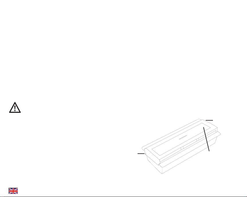
a) Place the doorbell pushbutton in such a way on the work
surface that the two rotation axes of the transparent
plastic face are at the rear (fig. 1 A and C).
Figure 1: Doorbell-pushbutton
A
C
B
Setup
English
2
TürttasterBA_08_08_15_CA.indd 2 06.10.2017 08:18:03
b) Using a pointed object (e.g. pen) carefully press now the
small pin on the left side (fig. 1 A).
c) Now you should be able to push up andremove the trans-
parent plastic face (fig. 1 A).
d) You can now open the small screw (fig. 1 B) using a small
Phillips screwdriver and remove the front of the doorbell
pushbutton behind which there is the PCB with the battery.
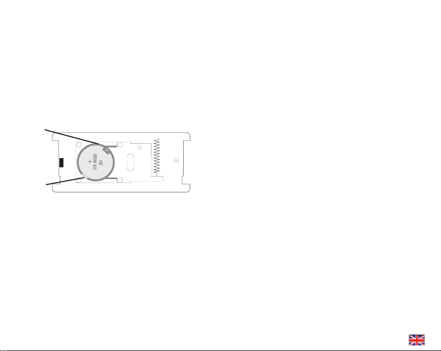
e) Insert the battery (coin cell CR 2032) into the plastic
support on the PCB (fig. 2 D).
Figure 2: Battery compartment
f) If you would like to replace a battery, remove the old
one with a small flat screwdriver from its plastic support
by lifting the edge slightly (fig. 2 E). Afterwards you can
insert a new battery. Kindly ensure correct polarity of
the battery.
g) Please refer to step 3 for the assembly of the doorbell
pushbutton.
2. Label name tag and insert
a) If you have not opened the housing yet, kindly proceed
as described under step 1 a) to c).
b) The transparent plastic face consists of two parts.
The labelled name tag can be inserted between them
(dimensions: 94 x 24 mm). Kindly ensure that the label-
ling is right way up. Kindly also keep in mind that the
name tag has a cutout that does not cover the light
diode or at least lets the light pass through.
c) Put the two transparent parts of the plastic face back
together so that the notches interlock.
d) Please refer to step 3 for the assembly of the doorbell
pushbutton.
3. Assembly
a) If you have changed only the name tag, proceed to step e)
b) Before assembling ensure that the small screw (fig. 1 B)
can grip at the right spot. If required turn one part of the
housing by 180°. Please make sure that the rubber gasket
sits correctly within the housing.
c) Insert the front face into the housing of the doorbell push
button and press both firmly together until the housing
parts lock in place.
d) Carefully drive in the small screw (fig. 1 B) with a small
Phillips screwdriver.
e) Now hold the doorbell pushbutton in such a way that
the small screw (fig. 1 B) is on the right.
f) At the right side of the pushbutton there is a small open-
ing (fig. 1 C) where the hinge pin of the transparent
plastic face can be inserted.
CR 2032
3V
D
E
English
3
TürttasterBA_08_08_15_CA.indd 3 06.10.2017 08:18:03
English
4
g) You can now position the transparent plastic face in such
a way until it has almost reached its final position. You
only have to carefully press the small pin (fig. 1 A) and to
lock the transparent plastic face in place.
4. Do not forget to register your doorbell-pushbutton with
your »signolux«-receivers!
a) Keep the function button of the according receiver pressed.
The symbols light up in sequence. Release the button
when the desired symbol is lit.
b) Press the doorbell-pushbutton.
c) Wait for approx. 20 seconds and test the function.
5. Mounting the doorbell pushbutton
You can mount the doorbell pushbutton using the supplied
strips of double-sided tape. Take care to adhere it to a
smooth, dry and clean surface.
Important note:
Kindly keep in mind that metal parts and other building
materials may interfere with the transmission of the radio
signal. As they can be either visible or hidden at the
desired mounting location you should always carry out
a functional test at the mounting location before starting
the mounting process, and, if required, choose a different
mounting or installation location if the reception is not
guaranteed.
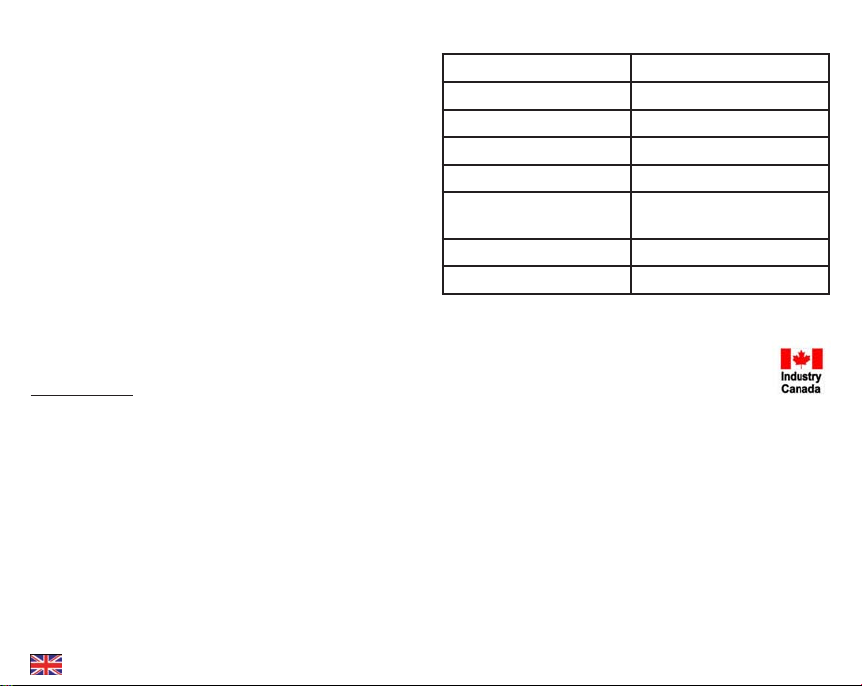
Technical data
Work range -10 bis 40°C
Radio frequency 418 MHz / 915 MHz
Range (open spaces) up to 200 m
HF capacity <10 mW
Battery CR2032
Battery service life
(5 activations per day)
18 months
Dimensions (HxWxD) 41 x 90 x 23 mm
Weight 41 g
This device complies to the following IC standards:
47 CFR Part 15; 2013
RSS-210 ISSUE 8
Technical specifications subject to change without prior notice.
TürttasterBA_08_08_15_CA.indd 4 06.10.2017 08:18:03

Français
5
Nous vous félicitons d‘avoir acheté un appareil « signo-
lux ». Vous avez opté pour un système moderne et fiable.
Veuillez lire l’intégralité de ce mode d’emploi avec attenti-
on afin de mettre en service l’appareil correctement et de
vous familiariser avec toutes les possibilités du système.
Contenu standard livré
Veuillez vérifier si toutes les pièces énumérées ci-dessous
sont incluses :
- Bouton de sonnette de porte
- Pile (CR2032)
- Ruban adhésif double-face
- Mode d’emploi
- Carte de garantie
S’il manque des pièces, veuillez vous adresser aux revendeurs
ou directement au fabricant.
Consignes de sécurité
- Avant de mettre en service et d’utiliser l’appareil, veuillez
lire attentivement et entièrement le mode d’emploi.
- Conservez soigneusement ce mode d’emploi pour qu’il
soit également accessibles aux autres utilisateurs.
- Respectez toujours les consignes du fabricant et portez
un équipement de protection adapté (par ex. lunettes de
protection) lorsque vous utilisez des outils électriques.
- Avant de commencer le perçage, vérifiez si des câbles
électriques et des conduites d’eau sont cachés dans
les murs. En cas de doute, il est recommandé d’utiliser
un détecteur de câbles et de conduites.
Principe de fonctionnement
Le système de signal lumineux se compose d’au moins un
émetteur (par ex. bouton de sonnette de porte) et d’un ré-
cepteur « signolux ». Le système permet d’intégrer jusqu’à
8 émetteurs.
Lorsque, par exemple, le bouton de sonnette est actionné,
un signal radio (impulsion radio de 418 MHz / 915MHz)
est transmis au récepteur « signolux ». Celui-ci retransmet
les signaux reçus de manière sonore et visuelle par des
sons et des signaux lumineux.
1. Mise en place et remplacement de la pile
Pour pouvoir mettre la pile bouton (type CR2032) en place,
vous devez d’abord ouvrir le compartiment à pile.
a) Posez le bouton de sonnette de porte sur le plan de tra-
vail de manière à ce que les deux pivots du cache en
plastique transparent (fig. 1A et C) se trouvent à l’arrière.
Figure 1: Bouton de sonnette de porte
A
C
B
Mise en service
TürttasterBA_08_08_15_CA.indd 5 06.10.2017 08:18:04
Français
6
b) À l’aide d’un objet pointu (par ex. stylo à bille), appuyez
ensuite prudemment sur la petite broche sur le côté
gauche (fig. 1A).
c) Le cache en plastique transparent doit alors pouvoir être
soulevé à gauche (fig. 1A) et retiré.
d) Vous pouvez maintenant ouvrir la petite vis (fig. 1B) avec
un petit tournevis cruciforme et retirer la partie avant de
du bouton de sonnette de porte derrière lequel se trouve
la platine avec la pile.
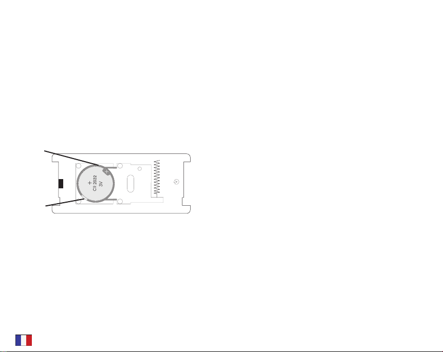
e) La pile (pile bouton CR 2032) peut maintenant être mise
en place dans le logement en plastique sur la platine
(fig. 2D).
Figure 2: Compartiment à pile bouton
f) Pour remplacer la pile, sortez la pile précédente de son
logement en plastique en la soulevant légèrement sur le
côté àl’aide d’un tournevis plat (fig. 2E). Vous pouvez
ensuite installer la nouvelle pile. Veuillez respecter la
polarité de la pile.
g) Pour l’assemblage de du bouton de sonnette de porte,
voir point 3.
2. Mettre une inscription sur l’étiquette et l’insérer
a) Si vous n’avez pas encore ouvert le boîtier, procédez tel
que décrit au point 1 a) à c).
b) Le cache en plastique transparent se compose de deux
pièces. L’étiquette portant votre inscription (dimensions :
94 x 24 mm) se glisse entre ces deux pièces. Veillez à
ce que l’inscription soit dans le bon sens. Veillez égale-
ment à ce que l’étiquette comporte une fente qui ne
couvre pas la diode électroluminescente ou que du
moins elle laisse transparaître la lumière.
c) Réassemblez les deux pièces transparentes du cache en
plastique de manière à ce qu’elles s’encliquètent.
d) Pour l’assemblage de du bouton de sonnette de porte,
voir point 3.
3. Assemblage du bouton de sonnette de porte
a) Si vous avez uniquement modifié l’étiquette, passez di-
rectement au point e).
b) Avant l’assemblage, veillez à ce que la petite vis (fig. 1B)
s’insère au bon endroit. Le cas échéant, tournez le boîtier
de 180°.
c) Insérez la partie avant dans le boîtier du bouton de son-
nette de porte et poussez prudemment sur les deux élé-
ments jusqu’à ce qu’ils s’encliquètent. Veillez à ce que le
joint en caoutchouc soit correctement placé.
d) Serrez prudemment la petite vis (fig. 1B) à l’aide d’un
tournevis cruciforme.
e) Placez ensuite le bouton de sonnette de porte de manière
à ce que la petite vis (fig. 1B) se trouve à droite.
CR 2032
3V
D
E
TürttasterBA_08_08_15_CA.indd 6 06.10.2017 08:18:04

f) À droite du bouton, se trouve une petite ouverture (fig. 1C),
dans laquelle la broche de charnière du cache en plas-
tique transparent peut s’insérer.
g) Vous pouvez maintenant poser le cache en plastique
transparent jusqu’à ce qu’il soit pratiquement en posi-
tion finale. Il vous suffit ensuite d’introduire prudemment
la petite broche (fig. 1A) et de faire s’encliqueter le
cache en plastique transparent.
2. N’oubliez pas de déclarer le bouton d’appel au
récepteurs »signolux« !
a) Maintenez la touche fonction de l’émetteur longuement
enfoncée. Les symboles s’illuminent les uns après les
autres. Relâchez la touche dès que le symbole souhaité
s’allume.
b) Actionnez le bouton de sonnette de porte.
c) Attendez env. 20 secondes et testez ensuite la fonction.
5. Fixation du bouton de sonnette de porte
Vous pouvez fixer le bouton de sonnette de porte à l’aide du
ruban adhésif à double face fourni.. Faites attention à une
surface lisse, propre et sec.
Remarque importante : Veuillez noter que les pièces mé-
talliques et d’autres matériaux de construction peuvent
gêner la propagation du signal radio. Comme ceux-ci peu-
vent être présents de manière visible ou invisible à l’endroit
de fixation ou d’installation, il est conseillé d’effectuer un
test radio à l’endroit exact de la fixation avant toute fixation
et le cas échéant de choisir un autre endroit de fixation
lorsque la réception n’est pas garantie.
Caractéristiques techniques
Plage d’opération -10 à 40°C
Fréquence radio 418 MHz / 915 MHz
Portée (aire dégagée) jusqu’à 200 mètres
Puissance HF <10 mW
Pile CR2032
Durée de vie de la pile
(5 utilisations par jour)
18 mois
Dimensions (HxlxP) 41 x 90 x 23 mm
Poids 41 g
Cet appareil est conforme aux exigences des directives de IC
suivantes :
47 CFR Part 15; 2013
RSS-210 ISSUE 8
Sous réserve de modifications techniques.
Français
7
TürttasterBA_08_08_15_CA.indd 7 06.10.2017 08:18:04

TürttasterBA_08_08_15_CA.indd 8 06.10.2017 08:18:04

Designed in Europe
Doorbell-pushbutton
Bouton de sonnette de porte
www.asatech.ca
TürttasterBA_08_08_15_CA.indd 9 06.10.2017 08:18:06
Table of contents
Languages:
Popular Accessories manuals by other brands

Alarmcom
Alarmcom ADC-IS-300-LP installation guide

PLX Devices
PLX Devices Legion 5.500mAh user manual

Next Century
Next Century LS4 quick start guide

Gleason Reel
Gleason Reel Dual Hose Reel-Direct Drive K24 Installation and maintenance instructions

MaxiCosi
MaxiCosi Coral XP manual

CORNING
CORNING LSE 71L instruction manual


