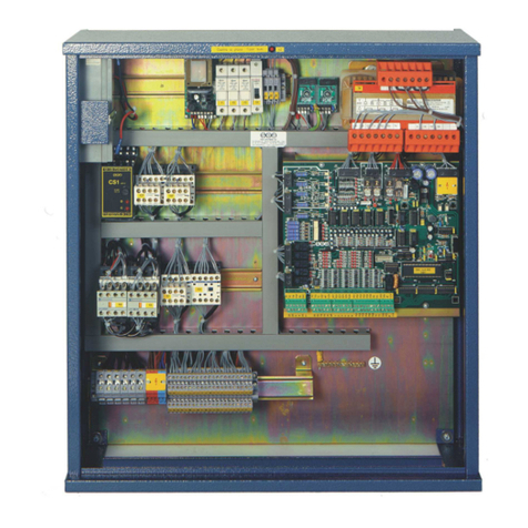
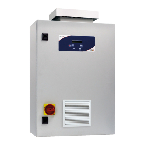
SEA STK3-GMV10 Reference manual

SEASYSTEMSS.R.L
Control Panels, Button Panels and Pre-wired Systems for Elevators
Via San Carlo 13 -20010 Bareggio -Milan -ITALY
Tel: +39 02 90 36 34 99 -Fax: +39 02 90 36 35 00
MSTK3-GB
Rev.03
20/07/09
MANUAL FOR
INSTALLATION AND USE
STK3-GMV10
Control panel and Pre-wiring
For Traction and Hydraulic Elevators

SEA SYSTEMS
INSTALLATION AND USE
STK3-GMV10 Control panel and Pre-wiring
For Hydraulic and Traction Elevators
MSTK3-GB
Rev.03
20/07/09
STK3-GMV10 Electric System Page 2of 76
INTRODUCTION
Thank you for choosing the STK3 Control panel for your system.
Please read this booklet carefully in order to learn about all of the features and the potential of this
device.
The control panels with microprocessors in the STK3 family are specifically designed for controlling
hydraulic and traction elevators in Universal or Simplex (grouped ascent and/or descent) operation.
Using the PT01 programmer it is possible to set a secret Access Code, determine the conditions of
elevator operation, monitor what malfunctions or breakdowns occurred and how many times they
occurred, control the operation of the elevator and its doors, and modify the functional
characteristics of the elevator.
Many specific functions for a particular system can be programmed without having to modify the
cabling of the Control panel.
The functional diagnostics for the system is provided by the PT01 programmer and by the
LED signals on the STK3-Bboard.
Warning
As our products are continuously evolving, the SEA SYSTEMS reserves the right to alter the
information contained in this manual without prior notice.
Support documentation will be supplied for the additional or modified functions of customized
products.

SEA SYSTEMS
INSTALLATION AND USE
STK3-GMV10 Control panel and Pre-wiring
For Hydraulic and Traction Elevators
MSTK3-GB
Rev.03
20/07/09
STK3-GMV10 Electric System Page 3of 76
INDEX
1. FUNCTIONAL FEATURES........................................................................4
2. INSTALLATION..........................................................................................5
2.1. GENERAL NOTES........................................................................................................................6
2.2. SAFETY MEASURES....................................................................................................................7
2.3. TERMS USED..............................................................................................................................7
2.4. PRELIMINARY OPERATIONS........................................................................................................8
2.5. FASTENING CONTROL PANEL.....................................................................................................9
2.6. CONNECTIONS FOR PRE-INSTALLATION OPERATIONS ............................................................11
2.7 IN SHAFT MOUNTING AND CONNECTIONS................................................................................14
2.8. CAB ROOF MOUNTINGS AND CONNECTIONS...........................................................................17
2.9. CONNECTIONS TO PANEL AND POWER-ON..............................................................................29
2.10ISOLATION TEST........................................................................................................................30
3. PROGRAMMING AND DIAGNOSTICS......................................................31
3.1 CHARACTERISTICS OF THE PT01 PROGRAMMER....................................................................31
3.2 WAIT CONNECTION AND MODE.................................................................................................31
3.3 PROGRAMMER PARAMETERS AND USE ...................................................................................32
3.4 IDENTIFICATION AND ACCESS...................................................................................................33
3.5. LEVEL OF ACCESS....................................................................................................................33
3.6 MENU TABLE.............................................................................................................................34
3.7 PARAMETERS............................................................................................................................36
4. MAINTENANCE........................................................................................73
4.1. BATTERY REPLACEMENT..........................................................................................................73
4.2. SHAFT SENSORS ......................................................................................................................73
4.3. REPLACEMENT OF THE STK3-BBASIC ELECTRONIC BOARD.................................................74
5. SOLUTIONS TO MOST FREQUENT PROBLEMS................................75
5.1. STK3-BBOARD IN ALARM (ALARM LED ON).......................................................................75
5.2. INCORRECT READINGS BY THE SHAFT SENSORS....................................................................75
6. TECHNICAL SPECIFICATION................................................................76

SEA SYSTEMS
INSTALLATION AND USE
STK3-GMV10 Control panel and Pre-wiring
For Hydraulic and Traction Elevators
MSTK3-GB
Rev.03
20/07/09
STK3-GMV10 Electric System Page 4of 76
1. FUNCTIONAL FEATURES
TYPE OF ELEVATORS CABLE
-HYDRAULIC DIRECT, STAR-DELTA, SOFT STARTER, SOFT STOP, ELECTRONIC
VALVE
OPERATIONS -SIMPLEX UNIVERSAL
-SIMPLEX GROUP DESCENT
-SIMPLEX GROUP ASCENT-DESCENT
NUMBER OF STOPS -FOR UNIVERSAL AND GROUP DESCENT:
BASIC 12 STOPS / 12 SERVICED
EXPANSION FOR 12 SERVICED (TOTAL 12 STOPS / 24 SERVICED)
--FOR GROUP ASCENT-DESCENT:
BASIC 7 STOPS / 7 SERVICED
EXPANSION FOR 12 SERVICED (TOTAL 12 STOPS / 12 SERVICED)
DOOR CONTROL -AUTOMATIC ON FLOORS AND IN CAB UP TO 2 OPERATORS WITH
ALTERNATING/CONTEMPORARY/SELECTIVE OPENING
-PHOTOCELL, OPEN/CLOSE DOOR BUTTON
-VARYING DOOR OPEN/CLOSED STOP ON DIFFERENT FLOORS
VARIOUS FUNCTIONS -VIEW AND DELETE BREAKDOWN/MALFUNCTION CODES
-SAFETY CONTROL
-PHASE SEQUENCE AND FAILURE
-TIMER MANAGEMENT (RUN TIME, LOW SPEED TIME)
-INTERMEDIATE CONTROL 15 S (HYDRAULICS)
-MAIN FLOOR STOP
-ADJUSTMENT OF LEVELING SPACE
-EARLY DOOR OPEN
-RESERVED/PREFERENTIAL/FIREMAN/FIRE OPERATION
-CUSTOMER SECRET ACCESS CODE
-PROGRAMMING OF INPUTS AND OUTPUTS FOR SPECIAL FUNCTIONS
IN CAB BUTTON PANEL
-POSITION DISPLAY
-NEXT DIRECTION ARROW
-SENT AND RECEIVED ALARM, INTERCOM
-EMERGENCY LIGHT
-OVERLOAD
-GONG
-OUT OF SERVICE
-CALL BUTTON (also for the EN 81-70 version)
FLOOR BUTTON PANEL
-POSITION DISPLAY
-NEXT DIRECTION ARROW
-CALL BUTTONS (also for the EN 81-70 version)
FLOOR INDICATOR -MAGNETIC PICK-UP, ENCODER
EMERGENCY -EMERGENCY DESCENT AND DOOR OPENING for hydraulic elevators (Data sheet
EM01)

SEA SYSTEMS
INSTALLATION AND USE
STK3-GMV10 Control panel and Pre-wiring
For Hydraulic and Traction Elevators
MSTK3-GB
Rev.03
20/07/09
STK3-GMV10 Electric System Page 5of 76
2. INSTALLATION
Fig. 2.1 -General pre-wiring layout with paragraphs for reference during installation
SHAFT
:
-Par. 2.7
CAB ROOF:
-Par. 2.8
CONTROL PANEL:
-Par. 2.5;
-Par. 2.6
-Par. 2.9

SEA SYSTEMS
INSTALLATION AND USE
STK3-GMV10 Control panel and Pre-wiring
For Hydraulic and Traction Elevators
MSTK3-GB
Rev.03
20/07/09
STK3-GMV10 Electric System Page 6of 76
2.1. GENERAL NOTES
NOTE
Read the warnings contained in this manual very carefully as they provide
important information for safety during installation, use and maintenance.
•Current norms must be respected for installation and maintenance, which are to be
performed according to the manufacturer's instructions by qualified professional
personnel.
•Improper installation or poor maintenance may cause damage to persons, animals
or things, for which the manufacturer is not responsible.
•If the equipment is sold or transferred to another owner, always make certain that
all of the documentation listed in the following point is provided with the equipment
so that the new owner and/or installer can consult it.
•The documentation to use for installation is the following:
-System design diagram (not provided by SEA SYSTEMS) Manual for
Installation and Use GMV10 Control panel and Pre-wiring System electric circuit
schematic diagrams System electric installation schematic diagrams
•This documentation must be kept by the system manager for correct and safe
installation and maintenance of the elevator. This documentation is considered an
integral portion of the system and must not be damaged. Pages must not be
removed. During use have care not to dirty the pages in order to preserve its
legibility.
•The terms of warrantee are indicated on the back of the product transport
documents. This warrantee provides the security that SEA SYSTEMS will support
its products should defects manifest within the established period. The warrantee is
null if the product is used incorrectly or is modified to alter its performance beyond
the original factory specifications.
•If it is necessary to con our Technical Service, provide the serial number for the
system.
The serial number can be found:
-On the adhesive label located on the outer side of the housing of the control panel
On the first page of the electronic circuit diagram for the system On the
programming page of the panel On the Compliance Declaration for the panel
•The serial number is essential for tracing the technical features of the system.
The address and the telephone number for our technical service can be found on
the cover of this manual.

SEA SYSTEMS
INSTALLATION AND USE
STK3-GMV10 Control panel and Pre-wiring
For Hydraulic and Traction Elevators
MSTK3-GB
Rev.03
20/07/09
STK3-GMV10 Electric System Page 7of 76
2.2. SAFETY MEASURES
•The installation of the equipment must be performed by a qualified technician, who
under his/her own responsibility guarantees following the standards for good
workmanship.
•Before performing any cleaning of maintenance operations, disconnect the
equipment from the electric mains using the general system switch.
•Always wear the necessary IPD (individual protection devices) (Fig. 2.1),
specifically:
--Helmet
-Gloves
-Coveralls closed at the writs
-Safety shoes
-Safety Belt
-Ear protection
Safety Signs
•Do not wear loose clothing or objects (necklaces, watches, ties...) and tie back long
hair.
•Do not keep sharp objects or objects that can puncture (ex. screwdrivers,
scissors...) in shirt pockets.
•Do not tamper with, spoil, or hide warning signs/labels: If illegible, request their
immediate replacement.
•To lift heavy loads, use suitable equipment in order to limit spinal injury due to
manual operations.
2.3. TERMS USED
NOTE
This symbol indicates relevant or important information for the personnel
involved.
WARNING
This symbol indicates information that if not respected may cause personal injury
or damage the system.
CAUTION
This symbol indicates that the operation described may cause physical injury to
the personnel involved if not performed in compliance with the worker safety
norms.

SEA SYSTEMS
INSTALLATION AND USE
STK3-GMV10 Control panel and Pre-wiring
For Hydraulic and Traction Elevators
MSTK3-GB
Rev.03
20/07/09
STK3-GMV10 Electric System Page 8of 76
2.4. PRELIMINARY OPERATIONS
Prior to beginning the installation procedure, perform the following controls and
preparatory steps:
A)PREPARATION OF THE PLACE OF INSTALLATION
•Check that there is an efficient lighting system in the room.
•Check that the roomand pit are clean.
•Check that the mains electricity has sufficient grounding (if this is not the case, halt
installation until the Customer has rectified the situation).
•Check that the shaft entrances are closed suitably.
•Set up a materials storage area near the shaft that is easily accessible for the
installers and not exposed to the elements.
•Check that all of the conduits and holes for the electric cables are free, available for
inspection, and well finished.
B)MATERIALS UNLOADING AND STORAGE
•Ensure that the characteristics of the Control Panel (Type of panel, meters, start-
ups ...) correspond to what was ordered and what is listed on the order
confirmation.
•Check that all of the material needed for installation is available, according to the list
attached to the documents for the panel. The part numbers for the materials are
located on the bags that contain the parts and are called out in the installation
instructions in this manual.
•Check the status of all components and materials upon receipt on site in order to
identify any possible damages due to transport. Immediately notify SEA SYSTEMS
S.r.l. is there are any missing or damaged parts.
•Store the electric and electronic components in a dry cool place, in their original
packaging.
•If, for any reason,immediate installation of the plant is not possible, periodically
check on the stored components to avoid damages caused by extended storage
under unfavorable conditions.
C)SCAFFOLDING
•Use regulation scaffolding for the installation. The scaffolding must have work levels
at each stop, approximately 0.5 m lower than the floor.
CAUTION
Scaffolding made completely or partially from metal must be grounded and
comply with the current safety standards.

SEA SYSTEMS
INSTALLATION AND USE
STK3-GMV10 Control panel and Pre-wiring
For Hydraulic and Traction Elevators
MSTK3-GB
Rev.03
20/07/09
STK3-GMV10 Electric System Page 9of 76
2.5. FASTENING CONTROL PANEL
a) Mounting the panel in a traditional Machine Room
-Fasten the two supports to the upper and lower parts of the control panel.
-Fix the panel to the wall
b) Mounting the panel in a Machine Room Cabinet
-Fasten the two supports to the upper and lower parts of the control panel.
-Hook the panel on the upper guide at the bottom of the cabinet
-Fasten the panel to the lower guide at the bottom of the cabinet

SEA SYSTEMS
INSTALLATION AND USE
STK3-GMV10 Control panel and Pre-wiring
For Hydraulic and Traction Elevators
MSTK3-GB
Rev.03
20/07/09
STK3-GMV10 Electric System Page 10 of 76
c) Mounting the panel on MRL systems guides
-Fasten the two supports on the upper and lower parts of the control panel.
-Fasten the support plates to the system guides at a distance equal to the height of
the control panel.
-Hook the panel on the upper support plates fixedon the guide
-Fasten to the lower support plates fixed on the guide

SEA SYSTEMS
INSTALLATION AND USE
STK3-GMV10 Control panel and Pre-wiring
For Hydraulic and Traction Elevators
MSTK3-GB
Rev.03
20/07/09
STK3-GMV10 Electric System Page 11 of 76
2.6. CONNECTIONS FOR PRE-INSTALLATION OPERATIONS
1. Check that the general mains switch of the Control panel (CP) is in the OFF position
2. Connect the tractor power line (L1, L2, L3), the pump motor (MC) the solenoid valves
(YD, YL, YP, YE), the temperature and pressure sensors (RT, STO, SPO1, SPO2,
SPO4) to the control panel as shown in the schematic diagram Dia. 2.6.1
3. Connect the use and installation button panel (p/n PBU01) to the control panel using
flexible cable No. 1 and the connection contained in kit PBU02 as shown in the
schematic diagram Dia. 2.6.2
4. Connect the connectors with the integrated bridges (p/n PBU02) according to the
schematic diagram Dia. 2.6.2 and based on they type of system:
-MRL System àInsert Connector XV6
-TR System (Reduced Head) àInsert Connector XV7
-FR System (Reduced Pit) àInsert Connector XV8
-Systems with GEV valve àInsert Connector XG1 (only during self-
tuning phase)
CAUTION
After the pre-installation operations all inserted connectors must be unplugged.
The connectors have bridges on the safeties.
5. Turn on the control panel using the general switch of theCP
6. Select the type of operation,Installation, using the PT01 keyboard (parameter 4.1)
7. Search by elimination for any eventual problems (see menu 1. Diagnostics)
8. Check the pump motor rotation

SEA SYSTEMS
INSTALLATION AND USE
STK3-GMV10 Control panel and Pre-wiring
For Hydraulic and Traction Elevators
MSTK3-GB
Rev.03
20/07/09
STK3-GMV10 Electric System Page 12 of 76
Dia. 2.6.1 Connections for Pre-installation Operations Schematic Diagram

SEA SYSTEMS
INSTALLATION AND USE
STK3-GMV10 Control panel and Pre-wiring
For Hydraulic and Traction Elevators
MSTK3-GB
Rev.03
20/07/09
STK3-GMV10 Electric System Page 13 of 76
Dia. 2.6.2Connections for Pre-installation Operations Schematic Diagram

SEA SYSTEMS
INSTALLATION AND USE
STK3-GMV10 Control panel and Pre-wiring
For Hydraulic and Traction Elevators
MSTK3-GB
Rev.03
20/07/09
STK3-GMV10 Electric System Page 14 of 76
2.7 IN SHAFT MOUNTING AND CONNECTIONS
2.7.1 SHAFT LINE (SHAFT UPRIGHT)
1. The shaft line is made up of a taped coil of colored or numbered unipolar wires, with insert
connectors and labeled for the panel side.
2. Fasten the shaft line conduit (p/n P-00060) using the provided plugs (p/n P-00075) near the
floor button panel, keeping it at most 1 m from the door.
If two operators, install the same conduit closest to the side with most services
NOTE
Insert the strap (p/n P-00074) in the plug (p/n P-00075) before fastening the
conduit. (Fig. 1).
3. Fasten the coil temporarily at the top of the shaft and lower it into the shaft from the top,
allowing it to descend along the side with the insert connectors, to the control panel. (Fig. 2)
Fig. 1 Fig. 2
4. Connect the connectors of the upright to the operations panel according to the installation
schematic diagrams.
5. Extend the coil starting from the panel side, fastening it with a few straps to the plugs that hold
the conduit until you reach the very top of the shaft.
CAUTION
If the cable is tool long when it reaches the top, cut the wires and isolate them
using electrical tape, or use the same connectors which were just removed.

SEA SYSTEMS
INSTALLATION AND USE
STK3-GMV10 Control panel and Pre-wiring
For Hydraulic and Traction Elevators
MSTK3-GB
Rev.03
20/07/09
STK3-GMV10 Electric System Page 15 of 76
2.7.2. SHUNT CONNECTIONS TO THE SHAFT LINE
The shunt connections to the line (see the installation schematic diagram) must be performed
using the red connectors for 0,75 mm2cables and blue connectors for 2,5 mm2ground cables (p/n
P-00084, P-00085) following the sequence shown in Figure 3.
Fig. 3 –Sequence of operations for shunt connections to the shaft line
NOTE
In general, the equipment that requires shunt connections are:
-Overrun
-Floor button panels
-Alarm sirens
-Shaft stop...
2.7.3. SERIES CONNECTIONS TO THE SHAFT LINE
The series connections to the line (see the installation schematic diagram) must be performed
using the orange connectors following the sequence shown in Figure 6.
Pay particular attention to connect the last device of the series according to Figure 4, whereas the
first devics in the series should be connected according to Figure 5.
Fig. 4 Fig. 5
Last Connection in the Series First Connection in the Series
NOTE
In general, the equipment that requires shunt connections are:
-Contacts for floor door open safety blocks
WIR
E COLORS
:
PINK
ORANGE
YELLOW / GREEN

SEA SYSTEMS
INSTALLATION AND USE
STK3-GMV10 Control panel and Pre-wiring
For Hydraulic and Traction Elevators
MSTK3-GB
Rev.03
20/07/09
STK3-GMV10 Electric System Page 16 of 76
Fig. 6 –Sequence of operations for series connections to shaft line
Open 3 polefemale connector
wsectioning blade
xSectioned L1 (phase)cable positionedin contact without pealing
yGround cable in contact without pealing
Position the lower and upper parts of the connector…
… and tighten using a wrench
Assembly of a male connector with a female connector
Press the conductors betweenthe rip-resistant clamps

SEA SYSTEMS
INSTALLATION AND USE
STK3-GMV10 Control panel and Pre-wiring
For Hydraulic and Traction Elevators
MSTK3-GB
Rev.03
20/07/09
STK3-GMV10 Electric System Page 17 of 76
2.8. CAB ROOF MOUNTINGS AND CONNECTIONS
2.8.1. MOUNTING THE CONNECTION BOX (BOX)AND MAKING FLEXIBLE CABLE CONNECTIONS
1. Attach the connection box using the screws provided
2. Bring the coils of flexible cables into the pit of the shaft
3. Connect the flexible cables (side where ground has eyelets) to the connectors of the cab box
according to the installation schematic diagrams and fasten them to the box using the ties
provided (p/n P-00074)
4. Fasten the flexible cables to the car using the cable-holder brackets supplied (p/n P-00089)
and the plugs (p/n P-00102) on the roof and bottom of the cab
5. Connect the flexible cables (side where grounds is without eyelets) of the operations panel
according to the installation schematic diagrams.
6. Fasten the wedge support bracket provided (p/n P-00086) in the shaft at approximately the
mid-point of the travel distance using the plugs supplied (p/n P-00102),
7. Fasten the flexible cables to the wedge support bracket in a position so that when the cab is at
the absolute end of run, the winds of the flexible cable do not touch the bottom of the shaft.
NOTE
To eliminate the problem of excess bagginess and winding of the flexible cables
in the shaft, move the wedge support bracket upwards.
Bear in mind that for every meter the wedge support bracket is raised, it
corresponds to approximately ½meter of lifting of the cables below the cabin.
8. Check that the flexible cables are not knotted in the shaft. If they are, disconnect the
connectors to the operations panel, straighten them, and reconnect them.
9. Fasten a bracket provided (p/n P-00089) to the wall of the pit at the point in which the flexible
cables start to rise vertically along the shaft.
2.8.2. CONNECTIONS TO THE CABIN BUTTON PANEL AND THE DOOR OPERATOR
Connect the cabin button panel and the operator according to the installation schematic diagram.
NOTE
When it is necessary to use the conduit (p/n P-00087) to hold the cables on the
roof of the cab, fasten it to the roof using the screws provided (p/n P-00101).

SEA SYSTEMS
INSTALLATION AND USE
STK3-GMV10 Control panel and Pre-wiring
For Hydraulic and Traction Elevators
MSTK3-GB
Rev.03
20/07/09
STK3-GMV10 Electric System Page 18 of 76
2.8.3. SHAFT WITHOUT ENCODER SENSORS MOUNTING AND CONNECTIONS
DESCRIPTION
The shaft houses the following sensors:
•Two timing devices (SRD, SRS) for the end floor speed change, toggle contacts
•A monostable contact (SIS) for stopping and speed changes when rising
•A monostable contact (SID) for stopping and speed changes during decent
•Two monostable contacts (SIZ1, SIZ2) for the safety circuit control
B)INSTALLATION
1. Mount the two bracketed shaft impulse generator kits (p/n PIV01 and PIV02) on the roof of
the cab as shown in the schematic diagram 2.8.3.1 shown below.
Dia. 2.8.3.1-Sensor Mounting Schematic Diagram For Shaft Without Encoder

SEA SYSTEMS
INSTALLATION AND USE
STK3-GMV10 Control panel and Pre-wiring
For Hydraulic and Traction Elevators
MSTK3-GB
Rev.03
20/07/09
STK3-GMV10 Electric System Page 19 of 76
2. Connect the impulse generators as shown in the installation schematic drawings
3. Set the operation mode to normal using menu 4.1.1Service\Operation\Mode
.1 Mode..
Normal
4. Commutate the shunt of the Inspection button panel on the roof of the cab to the
maintenance mode.
5. Position the pair of magnets for the SRD and SRS timing devices according to the schematic
diagram Dia.at the distances from the end floors indicated in table Tab. 2.8.3.1 shown below.
6. Position the magnetic strips for stopping and speed changes as shown in the schematic
diagram Dia. 2.8.3.2 and table Tab. 2.8.3.1;
Tab. 2.8.3.1 Speed Change Distances Recommended for Traditional Shaft and Valve 3010
Cabin Speed
(m/s) KS:Speed
Change Distance
When Rising
(mm)
KD:Speed
Change Distance
When
Descending (mm)
0.01 ÷0.30 250 350
0.31 ÷0.40 350 450
0.41 ÷0.50 450 550
0.51 ÷0.60 600 700
0.61 ÷0.70 800 900
0.71 ÷0.80 1000 1100
7. Adjust the stop strips for intermediary floors so that the floor of the cab comesto the same
level of the floor threshold.
8. Should it be desirable to create a zone of non-detection during decent larger than that set by
the hysteresis of the monostable contacts, perform the following procedure:
Lower the IS contact strip to the space equal to that of non-detection desired. Adjust the
timing parameter 3.3.7 so that the cab again stops level with the floor
9. Adjust the stop strips for the other floors so that the cab floor reaches the floor threshold in a
level manner.

SEA SYSTEMS
INSTALLATION AND USE
STK3-GMV10 Control panel and Pre-wiring
For Hydraulic and Traction Elevators
MSTK3-GB
Rev.03
20/07/09
STK3-GMV10 Electric System Page 20 of 76
Dia. 2.8.3.2 Magnet Set-Up Overview for Shaft without Encoder
Other manuals for STK3-GMV10
1
Table of contents
Other SEA Control Panel manuals

